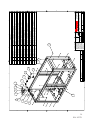
1
185-210 DUS
JD 4045
OMEGA TOOL
OPERATORS, MAINTENANCE,
AND PARTS MANUAL
SERIAL NUMBER_________________________________________
MODEL NUMBER_________________________________________
P/N: 307271
06/17/2008 MCM
TABLE OF CONTENTS
INTRODUCTION .............................................................................................................................. 6
SECTION 1 SAFETY ......................................................................................................................... 9
1.1
1.2
1.3
1.4
1.5
PARKING ....................................................................................................................................... 9
BEFORE STARTING THE COMPRESSOR ................................................................................ 9
COMPRESSOR USE AND COMPRESSED AIR ........................................................................ 9
SERVICING .................................................................................................................................. 10
LIFTING ....................................................................................................................................... 10
SECTION 2 DESCRIPTION ........................................................................................................... 11
2.1
2.2
2.3
2.4
2.5
2.6
INTRODUCTION ......................................................................................................................... 11
ROTARY COMPRESSOR COMPONENTS .............................................................................. 11
ENGINE COMPONENTS ........................................................................................................... 12
CHASSIS ...................................................................................................................................... 13
ENCLOSURE ............................................................................................................................... 13
INSTRUMENT PANEL DOOR ................................................................................................... 13
SECTION 3 OPERATION .............................................................................................................. 14
3.1
3.2
3.3
3.4
START UP PREPARATION ........................................................................................................ 14
STARTING PROCEDURE .......................................................................................................... 14
EMERGENCY SHUTDOWN PROCEDURE ............................................................................ 14
ROUTINE SHUTDOWN PROCEDURE .................................................................................... 14
SECTION 4 MAINTENANCE ....................................................................................................... 15
4.1 ENGINE FUEL SPECIFICATIONS ............................................................................................. 15
4.2 ENGINE OIL AND FILTER ......................................................................................................... 16
4.3 ENGINE COOLING SPECIFICATIONS ..................................................................................... 16
4.4 FAN ............................................................................................................................................... 17
4.5 RADIATOR PRESSURE CAP .................................................................................................... 17
4.6 RADIATOR ................................................................................................................................... 17
4.7 COMPRESSOR OIL .................................................................................................................... 17
4.8 COMPRESSOR & ENGINE AIR FILTER MAINTENANCE ................................................... 20
4.9 COMPRESSOR OIL THERMOSTATIC VALVE ....................................................................... 21
4.10 COMPRESSOR AIR/OIL SEPARATOR ................................................................................... 21
4.11 BELTS & BELT ADJUSTMENT .............................................................................................. 21
4.12 CONTROLS-OPERATION AND ADJUSTMENTS ................................................................. 22
4.13 INSTRUMENTS ........................................................................................................................ 23
4.14 BATTERY ................................................................................................................................... 23
4.15 MAINTENANCE SCHEDULE ................................................................................................. 24
4.16 DAILY OPERATION ................................................................................................................. 24
4.17 MAINTENANCE SCHEDULE CHART................................................................................... 25
4.18 RECOMMENDED SPARE PARTS LIST ................................................................................. 26
4.19 PROCEDURE FOR ORDERING PARTS ................................................................................. 26
SECTION 5 TROUBLESHOOTING ............................................................................................ 27
5.1 TROUBLESHOOTING ................................................................................................................ 27
5.2 TROUBLESHOOTING CHART ................................................................................................. 28
WARRANTY ..................................................................................................................................... 31
SECTION 6 ASSEMBLY_DRAWINGS ......................................................................................... 37
4
P/N: 307271
INTRODUCTION
OWNER’S RESPONSIBILITY
Your new Boss air compressor was engineered, built and tested to ensure the user both dependable and
economical service. This compressor has also been certified as conforming to the applicable Noise Emission
standards of the Environmental Protection Agency.
Continuation of this unit’s performance depends upon the care it receives during use. Therefore, operation
and maintenance procedures described in this manual should be followed carefully. The operator and
service personnel responsible for the care of this unit should be thoroughly familiar with this information.
It is the owner’s and/or operator’s responsibility to perform all safety checks and to ensure that all lubrication,
maintenance instruction and recommended practices are followed for safe operation. If disassembly or
replacement is required, particularly of internal parts, we recommend the owner see his dealer and not
attempt the repair himself.
It is owner’s responsibility to ensure that the preventive maintenance program is followed at the recommended
intervals. Proper care and service will assure long service life with a minimum of problems and operating
expenses.
We recommend that the owner and operator be thoroughly familiar with the contents of the manual.
If you encounter difficulties which you cannot diagnose our service personnel are prepared to help you.
Our toll free number is 1-800-635-6587. Outside the continental United States and Canada our number is
219-324-7776.
The model and serial number information is requested on all correspondence. This information can be
found on the Model Number Identification Plate. The information contained on the identification plate
should be transferred to the cover page of the manual for future reference.
6
P/N: 307271
WARNING
ALL UNITS ARE SHIPPED WITH A DETAILED OPERATORS AND PARTS MANUAL.
THIS MANUAL CONTAINS VITAL INFORMATION FOR THE SAFE USE AND
EFFICIENT OPERATION OF THIS UNIT. CAREFULLY READ THE OPERATORS
MANUAL BEFORE STARTING THE UNIT. FAILURE TO ADHERE TO THE
INSTRUCTIONS COULD RESULT IN SERIOUS BODILY INJURY OR PROPERTY
DAMAGE.
AIR COMPRESSOR SAFETY PRECAUTIONS
Safety is basically common sense. There are standard safety rules but each situation has its own peculiarities,
which cannot always be covered by rules. Therefore with your experience and common sense, you are in
a position to do something about safety. Lack of attention to safety can result in: accidents, personal
injury, reduction of efficiency and worst of all - Loss of Life. Watch for safety hazards. Correct them
promptly. Use the following safety precautions as a general guide to safe operation:
Do not attempt to remove any compressor parts without first relieving the entire system of pressure.
Do not attempt to service any part while machine is operating.
DANGER
CHECK THE COMPRESSOR SUMP OIL LEVEL ONLY WHEN THE COMPRESSOR
IS NOT OPERATING AND SYSTEM IS COMPLETELY RELIEVED OF PRESSURE.
OPEN SERVICE VALVE TO ENSURE RELIEF OF SYSTEM AIR PRESSURE WHEN
PERFORMING MAINTENANCE ON COMPRESSOR AIR/OIL SYSTEM. FAILURE
TO COMPLY WITH THIS WARNING MAY CAUSE DAMAGE TO PROPERTY AND
SERIOUS BODILY HARM.
Do not operate the compressor at pressures or speeds in excess of its rating.
Periodically check all safety devices for proper operation.
Do not play with compressed air. Pressurized air can cause serious injury to personnel.
Exercise cleanliness during maintenance and when making repairs by covering parts and exposed openings.
7
P/N: 307271
USER MODIFICATION
This Boss compressor incorporates numerous features to minimize noise emissions from the unit during
operation. This configuration has been tested for noise emissions at conditions specified by the U.S.
Environmental Protection Agency. Conformance to regulations requires the incorporation of the following
notification and definition in the OPERATION AND MAINTENANCE MANUAL.
TAMPERING WITH NOISE CONTROL SYSTEM PROHIBITED
Federal law prohibits the following act:
1.
The removal, rendering inoperative, other than for purposes of maintenance, repair or replacement
of any device or element of design incorporated into any new compressor for the purpose for noise
control prior to its sale or delivery to the ultimate purchaser.
2.
The use of the compressor after such device or element of design has been removed or rendered
inoperative by any person.
Among the acts included in the prohibition against tampering are those listed:
1.
2.
3.
Removal or rendering inoperative any of the following:
a. The engine exhaust system including the manifold, muffler or tailpipe.
b. Any of the enclosure components and associated sound barrier materials.
c. The sound baffles in the intake, exhaust and cooling system gas paths.
d. The air intake system including the air cleaner, the intake ducting, valve cover and gaskets.
Removal of any of the following:
a. Engine mounts or other sound isolating barriers in the system.
b. Fan shrouding and sound hood.
Operation of the compressor with any of the enclosure doors open.
8
P/N: 307271
SECTION 1 SAFETY
1.1 PARKING
CHOOSING A PARKING SITE
1.
Park the compressor on a level firm area. Never park on a grade of more than 15 degrees (27%).
If you must park on any grade, park across the grade so that the compressor does not tend to roll.
2.
Park so that the wind carries exhaust fumes and radiator heat away from the compressor inlet.
3.
Park away from work site dust.
4.
Stay clear of electrical power lines. Keep the towing vehicle or equipment carrier, compressor,
hoses, tools and all personnel at least 10 feet from power lines and buried cables.
1.2 BEFORE STARTING THE COMPRESSOR
1.
2.
3.
4.
5.
Check fluids levels and for possible leaks.
Use adequate hose and couplings with safety locks or pins.
Remove all tools and/or loose items from engine compartment.
Relieve any pressure in receiver tank.
Use proper eye and ear protection.
1.3 COMPRESSOR USE AND COMPRESSED AIR
1.
2.
3.
4.
5.
6.
7.
8.
9.
10.
12.
13.
14.
15.
Air from this machine is not fit for human breathing or food processing.
Never operate in an enclosed area.
Never use compressed air to clean your clothes and never direct it at another person, it can kill.
Always wear eye protection.
Install velocity fuse (“OSHA”) upstream of hose to prevent hose whip in case of a rupture.
Keep doors or hoods closed on machines in operation.
Do not touch hot surfaces or moving parts, such as exhaust or fans.
Do not adjust or restrict relief valves.
Do not refuel while machine is running; shut down and allow to cool before refueling.
Do not jump-start with cable connections directly on battery.
Do not use air at pressure higher than 30 PSIG (207 KPA) for cleaning purposes. Use of higher air
pressure can cause injury to the operator.
Keep compressor panels closed except when making repairs, adjustments, or servicing the
compressor.
Make sure all personnel are out of and clear of the compressor before starting or operating it.
Do not use either cylinder or air line antifreeze compound in confined area.
9
P/N: 307271
1.4 SERVICING
1.
2.
3.
4.
5.
6.
7.
8.
9.
10.
Before servicing compressor, relieve receiver pressure and allow to cool.
Be sure all access panels are opened and/or removed.
Wipe up all spills resulting from servicing.
Disconnect the grounded (negative) battery connection before making repairs or cleaning inside
the enclosure.
Do not use flammable solvents for cleaning the compressor.
Radiator coolant is under pressure. Do not remove radiator cap quickly, it may cause spray of
scalding coolant and severe burns to operator.
Make repairs only in clean, dry and well-lighted and well-ventilated areas.
Keep all parts of the body and any hand held tools or other metal objects away from exposed live
parts of the electrical system.
Replace damaged fuel tanks or lines immediately. DO NOT WELD on or near fuel tanks or lines.
Make sure all personnel are out of the compressor before closing and/or replacing panels.
1.5 LIFTING
1.
2.
3.
If the compressor is provided with a lifting bail, then lift by the bail. If no bail is provided, then lift
by sling.
When lifting by helicopter, use a sling. Do not lift by unit lifting bail.
Inspect the entire lifting, rigging and supporting structure to ensure it is in good condition and has
a rated capacity of at least the gross weight of the compressor plus 50%.
10
P/N: 307271
SECTION 2 DESCRIPTION
2.1 INTRODUCTION
Your Boss compressor is a gas/diesel driven Rotary Screw Compressor unit that provides superior
performance and reliability along with a minimal amount of required maintenance.
2.2 ROTARY COMPRESSOR COMPONENTS
COMPRESSOR DESCRIPTION
The compressor assembly is a positive displacement, oil flood lubricated, screw type unit employing one
stage of compression to achieve the desired pressure. Components include a housing (stator), two screws
(rotors), gears, bearings and bearing supports.
In operation, two helical grooved rotors mesh to compress air. Inlet air entering the casing is compressed
as the male lobes roll down the female grooves, pushing trapped atmospheric air along and compressing it
in one stage of compression. This process delivers smooth-flowing air at full pressure to the receiver.
To illustrate the compression sequence, consider the action of the male lobe as similar to a ball. As a helix
rotates, the ball (male lobe) meshes with the groove to start a compression cycle with trapped atmospheric
air. As the ball moves down the groove, air is compressed. Atmospheric air fills in behind the ball preparing
the groove for another compression cycle as rotation continues and the male lobe again meshes with the
groove.
During the compression cycle, oil is injected into the compressor for the purpose of lubrication, cooling
and sealing. Compressed air laden with oil leaves the compressor unit through a discharge port, which is
designed to give optimum performance within the desired discharge pressure range.
AIR FILTER
The Rotary Screw Compressor unit and engine are protected by a high efficiency, two-stage air filtering
system. This is a dry filter that requires maintenance when the air filter restriction gauge says it is time.
OIL COOLING
The compressor is an “oil flooded” compressor. The oil lubricates, seals and cools the internals of the
compressors as it is injected into the compressor. The oil goes through the compressor with the air where
it picks up the heat generated by the compression process then seals the spaces between moving parts and
lubricates bearings. The hot oil must be cooled. It is separated from the air, passed through the oil cooler
(mounted next to the engine radiator), through a thermostatic valve (that helps to rapidly warm cold oil at
start-up), then through a full flow oil filter and then back into the compressor. See instructions 4.10 and
4.13 for oil filter element and air/oil separating element servicing.
11
P/N: 307271
AIR/OIL SEPARATOR
At the compressor discharge the compressed air and the hot oil flow into a steel ASME coded pressure
vessel (rated at 175 psig-250psig) that acts as a reservoir for the air and separates out the oil. From the
bottom of this oil sump the oil leaves the vessel on its way to the oil cooler. The air and the slight oil mist
still entrained in the air flow through the separator element, which removes the last of the oil from the air.
The air passes on out to its final use and the separated oil goes through the scavenge line to the compressor
to re-enter the system.
As the compressor air leaves the receiver it goes through a minimum pressure valve that is set to maintain
at least 80 psig (55kpa) in the receiver when the compressor is running. The purpose of this pressure is to
ensure that there is pressure to force the oil out of the bottom of the receiver, through the oil cooling system,
so that sufficient oil is injected into the compressor.
CONTROL SYSTEM
The Boss compressor system is simple to operate. Starting procedure is explained in section 3 and on the
instrument panel door of the compressor. Each machine has an On/Off switch and a safety bypass switch
that bypasses the safety shutdowns. Once the machine is “on line” and in the run position, control is
automatic. The control system senses the need for air and adjusts the speed of the engine and compressor
as well as the opening of the compressor inlet valve to supply the amount of air needed. If the air demand
is zero, the engine and compressor “idle” and the inlet valve is shut to control the air entering the compressor.
If the demand is maximum, the opposite happens, full speed and wide-open inlet valve. Intermediate air
demands give intermediate speeds and valve openings for maximum operating efficiency. Service and
adjustments are in section 4.14.
2.3 ENGINE COMPONENTS
ENGINE DESCRIPTION
The engine in each Boss compressor system is selected to have reserve horsepower and speed necessary to
drive the compressor and all accessories when operating up to a discharge pressure 100 psig (686kpa) to
220 psig (1509kpa).
RADIATOR
The radiator is selected to handle the heat load of the engine. Mounted next to the compressor oil cooler.
Cooling air is moved through these two coolers with a specially selected engine fan. The system is designed
to handle extreme heat conditions.
FUEL SYSTEM
All units are supplied with fuel tank capacity adequate for a day’s normal operation, fuel filtering system
and optional low fuel shutdown. See section 4.3 for fuel servicing.
MUFFLER
Engine noise is reduced by a durable, low restriction engine muffler.
12
P/N: 307271
2.4 CHASSIS
FRAME
The entire compressor frame and body is “utilized” and constructed of 3/16" or 10 gauge steel plate,
resulting in light weight while providing a much stronger body than conventional designs of light sheet
metal over structural members.
2.5 ENCLOSURE
Enclosure is 14 gauge metal with powder coat finish. Each access panel has lockable handles with mechanical
props.
2.6 INSTRUMENT PANEL DOOR
Lockable instrument panel doors provide access to all controls and gauges.
13
P/N: 307271
SECTION 3 OPERATION
3.1 START UP PREPARATION
1.
Check engine and compressor oil levels. Do not overfill.
2.
Check coolant level in radiator (Fill at coolant recovery bottle).
3.
Check for fuel, oil and coolant leaks.
4.
Check air cleaner, clamps and hoses.
5.
Check battery connections.
6.
Check and adjust tension of fan belts.
NOTE: This unit has minimum air pressure valve to assure compressor oil flow. There will be no airflow
from the compressor if receiver pressure is less that 80 PSIG.
3.2 STARTING PROCEDURE
1.
2.
3.
Close service valves and move unloader valve to “START” position
Press and hold bypass button and turn starter switch to “START” position. If engine fails to start.
DO NOT attempt to restart until cranking motor stops rotating. Before restarting, starter switch
must be returned to “OFF” position
When engine starts, release starter switch and hold bypass button down until oil pressure reaches
15PSI then release. Maintain unloader valve at “START” position until engine is warm and
operating smoothly, then move unloader valve to “RUN” position.
3.3 EMERGENCY SHUTDOWN PROCEDURE
Turn start stop switch to “OFF” position
3.4 ROUTINE SHUTDOWN PROCEDURE
1.
2.
3.
Move unloader to start position
Allow compressor to run 2 to 3 minutes to cool.
Move on/off switch to “OFF” position
14
P/N: 307271
SECTION 4 MAINTENANCE
4.1 ENGINE FUEL SPECIFICATIONS
WARNING
DO NOT MIX GASOLINE OR ALCOHOL WITH DIESEL FUEL. THIS MIXTURE
CAN CAUSE AN EXPLOSION.
CAUTION
DUE TO THE PRECISE TOLERANCES OF DIESEL INJECTION SYSTEMS, IT IS
EXTREMELY IMPROTANT THAT THE FUEL BE KEPT CLEAN AND FREE OF DIRT
OR WATER. DIRT OR WATER IN THE SYSTEM CAN CAUSE SEVERE DAMAGE TO
BOTH THE INJECTION PUMP AND THE INJECTION NOZZLE.
USE ASTM NO.2D FUEL WITH A MINIMUM CETANE NUMBER OF 40. NO.2 DIESEL.
FUEL GIVES THE BEST ECONOMY AND PERFORMANCE UNDER MOST
OPERATING CONDITIONS. SEE ENGINE MANUFACTURES OPERATORS/
INSTRUCTION MANUAL FOR THE PROPER ENGINE FUEL FOR THE BRAND
ENGINE IN YOUR BOSS COMPRESSOR.
HIGH ALTITIDE AND LOW TEMPERATURE FUELS
Fuels with cetane numbers higher than 40 may be needed in high altitudes or extremely low ambient
temperatures to prevent misfires and excessive smoke.
COLD WEATHER FUEL
At opening temperatures below 0 degrees C (32 degrees F) use a blend of No.1D and No.2D fuels, also
know as “winterized” No.2D. NOTE: No.1D fuel can be used; however, fuel economy will suffer.
Use low sulfur content fuel having a cloud point that is at least 10 degrees below the lower expected fuel
temperature. Cloud point is the temperature at which wax crystals begin to form in diesel fuel.
The viscosity of the fuel must be kept above 1.3 centistokes to provide adequate fuel system lubrication.
ENGINE FUEL FILTER
See engine manufactures operator/instruction manual for the proper fuel filter replacement changing intervals
for the brand engine in your Boss compressor.
WARNING
KEEP HANDS AND FINGERS CLEAR OF FUEL FITTINGS. HIGH PRESSURE OF
THE FUEL CAN CAUSE PENETRATION OF THE SKIN. SEEK IMMDIATE MEDICAL
ATTENTION IF SKIN IS BROKEN BY THE FUEL SPRAY.
15
P/N: 307271
4.2 ENGINE OIL AND FILTER
See engine manufactures operator/instruction manual for the proper engine oil and filter changing intervals
for the brand engine in your Boss compressor.
OIL FILTER REPLACEMENT
1.
Clean the area around the lubricating filter head.
2.
Remove the filter.
3.
Clean the o-ring surface of the filter head.
NOTE: The o-ring can stick on the filter head. Make sure it is removed.
4.
Apply a light film of lubricating oil to the o-ring-sealing surface before installing.
5.
Install the filter as specified by the filter manufacturer.
CAUTION
MECHANICAL OVER-TIGHTENING MAY DISTORT THE THREADS OR DAMAGE
THE FILTER ELEMENT SEAL.
4.3 ENGINE COOLING SPECIFICATIONS
Diesel engines require a balanced coolant mixture of water and ethylene glycol base antifreeze. This
protects the engine cooling system from corrosions as well as freezing damage. The Boss compressor is
shipped from the factory with a 50/50 mixture of water and ethylene glycol. In tropical climates where
freeze protection is not required, glycol engine coolant should still be used. It will help prevent corrosion
and pitting of cylinder liners. See engine manufactures operator/instruction manual for the proper engine
coolant for the brand engine in your Boss compressor.
MIXTURES:
Antifreeze concentration level should not exceed recommended levels. Doing so can cause cooling system
failure.
· Use a high quality, low silicate antifreeze
· A mixture of 50% antifreeze and 50% water is required for temperatures above –37 º C (-34 ºF).
· A mixture of 60% antifreeze and 40% water us required for environments below –37 ºC (-34 ºF). This
provides protection to –54 ºC (-65 ºF).
· Never exceed a 60% antifreeze and 40% water mix.
ENGINE COOLING SYSTEM
All engines have a pressurized cooling system that contains a 50/50 mixture of water and ethylene glycol.
Daily maintenance of the system includes a check of the coolant level, proper belt adjustment of fan and
water pump drives, soundness of fan and cleanliness of the radiator and oil cooler to permit airflow. Further
cooling system maintenance is defined in the engine maintenance manual.
16
P/N: 307271
COOLANT LEVEL
Before each start-up, when radiator is cold, the coolant should be checked. When needed, refill with a 50/
50 solution of water and ethylene glycol, DO NOT use 100% antifreeze for “topping off”.
WARNING
CHECK THE COOLANT LEVEL ONLY WHEN THE ENGINE IS STOPPED AND THE
TEMPERATURE IS BELOW 160ºF (70ºC) FAILURE TO DO SO CAN CAUSE
PERSONAL INJURY FROM HEATED COOLANT SPRAY.
4.4 FAN
Check the fan for cracks, loose rivets, and bent or loose blades. Make sure it is securely mounted. Tighten
the cap screws if loose. Replace damaged fans.
WARNING
NEVER USE THE FAN TO ROTATE THE ENGINE. THE BLADE(S) CAN BE
DAMAGED CAUSING A FAN FAILURE, WHICH CAN RESULT IN PERSONAL INJURY
OR PROPERTY DAMAGE.
4.5 RADIATOR PRESSURE CAP
If coolant continually spills from radiator through the overflow then the radiator cap should be tested and/
or replaced with a cap of the same pressure rating, generally 13 PSI. Be sure cap is turned to the proper
secure position.
4.6 RADIATOR
Any sign of leakage from the radiator may justify a pressure test to assure its soundness. Radiator leaks
should only be repaired by qualified service people. Dirt that clogs the cooling fins of the radiator should
be removed. The use of an air stream of high-pressure steam cleaner should be done with caution so as to
not damage the delicate fins. Bent cooling fins will reduce the cooling capability of the radiator.
4.7 COMPRESSOR OIL
The life and proper operation of the compressor is dependent on adequate and clean compressor oil.
DEXRON® - III Automatic Transmission Fluid is supplied with the new machine and should be used for
proper level maintenance and for oil changes. We recommend that you use DEXRON® - III Automatic
Transmission Fluid.
WARNING
DO NOT REMOVE CAPS OR OTHER COMPONENTS WHEN COMPRESSOR IS
RUNNING OR PRESSURIZED. BEFORE DOING SO, STOP COMPRESSOR AND
RELIEVE ALL INTERNAL PRESSURE.
17
P/N: 307271
COMPRESSOR OIL SPECIFICATIONS
It is permissible to use oils other than the ATF shown above; such as Hydraulic oil. If they are used then
they must have at least the following minimum properties:
• ISO grade
32
• CPS No.
255675
• API Gravity
• Viscosity, Kinematic
cst at 40 degrees C
33.6
cst at 100 degrees C 5.5
• Viscosity saybolt
SUS at 100 degrees F 173
SUS at 210 degrees F 45
• Viscosity index
98
• Pour point deg. C(deg F) -33(-27)
• Flash point deg.C(deg.F) 204(399)
• Oxidation stability
• Hours to 2.0 mg KOH/g
acid no., ASTM D 943 >600
The advantage in using DEXRON® - III in the compressor is that it is good lubricant suitable to its application
and it is readily available. There are other oils that may be used that have longer life. They are better able
to stand the extreme operating conditions. Whether or not to use these oils is a decision that depends upon
the operating conditions. Very frequent oil changes are necessary in extremely hot, dirty operating conditions
and if the compressor is operating in a remote, difficult-to-reach service location then perhaps it would be
better to use the DEXRON® - III because of availability and cost. If, however service is convenient and
attentive so that the oil can be used for as long as it will provide good protection; then higher quality oils
may be used that will extend the life of the compressor.
WARNING
BOSS DOES NOT RECOMMEND MIXING DIFFERENT TYPES OF OILS. WHEN
CHANGING TO A DIFFERENT TYPE OIL, CLEAN COOLER, AIR/OIL RECEIVER
AND LINES THOROUGHLY.
ADDING COMPRESSOR OIL
1.
Level the compressor to assure oil level indicator will be accurate.
2.
Remove any dirt around fill cap, which is located on or near the air/oil receiver and then remove
the fill cap itself.
3.
Inspect the fill cap for damage and cleanliness. Replace if necessary.
4.
Proper oil can then be added until the oil level reaches halfway in the sight-level tube or the
“bullseye”.
5.
Replace full cap securely-never put cap on without tightening immediately.
6.
Do not over fill the sump tank. This will cause oil to spray out of the blowdown valve and/or
service valve.
18
P/N: 307271
CAUTION
DO NOT REPLACE FILL CAP WITH A PIPE CAP; SERIOUS INJURY OR DAMAGE
COULD RESULT. THE THREADS ARE DIFFERENT. ALWAYS ENSURE A STRAIGHT
THREAD FILL CAP IS USED.
CHANGING COMPRESSOR OIL
1.
Oil and air filter will help prolong oil life. If the oil appears dirty or it has a foul smell it should be
replaced.
2.
Change compressor oil and filter every 500 hours.
3.
Remove fill cap and drain oil from the bottom of the air/oil receiver. Oil will drain more quickly
and completely if it is warm from operation.
4.
Close all drains and replace oil with fresh oil to proper level. Replace fill cap and run the unit
briefly to see if more oil needs to be added and to ensure there or no leaks.
COMPRESSOR OIL FILTER
The oil filter in the compressor lubrication system is of the full flow spin-on canister type. Initially the
filter should be replaced after the first 50 hours, then every 500 hours or sooner if indicated. A dirty filter
can restrict oil flow, causing high oil temperature condition, which will result in a unit shutdown.
CAUTION
SUBSTITUTE FILTERS MAY HAVE INADEQUATE WORKING PRESSURE LIMITS,
RESULTING IN ELEMENT LEAKAGE OR RUPTURE. REPLACEMENT FILTERS
MUST BE THE SAME QUALITY AND TYPES AS THE ORIGINAL BOSS AIR
COMPRESSORS FILTER.
COMPRESSOR OIL FILTER REPLACEMENT
1.
Using a strap wrench, remove the old element and o-ring.
2.
Clean o-ring seating surface.
3.
Apply a light film of oil to the new o-ring.
4.
Hand tighten new element until new o-ring is seated in the o-ring groove.
5.
Continue tightening element by hand an additional ½ to ¾ turn.
6.
Restart machine and check for leaks.
CAUTION
MECHANICAL OVER-TIGHTENING MAY DISTORT THE THREADS OR DAMAGE
THE FILTER ELELMENT SEAL.
19
P/N: 307271
4.8 COMPRESSOR & ENGINE AIR FILTER MAINTENANCE
ELEMENT REPLACEMENT
1.
Loosen the clamps that secure the dust cup to the body and remove the cover.
2.
Empty the dirt from the dust cup.
3.
Remove the element.
4.
Clean the canister and dust cap with a damp cloth inside and out. DO NOT blow dirt out with
compressor air.
5.
At this time clean or replace the element.
6.
Replace the element.
7.
Reposition the cover and tighten the clamp, INSTALL WITH “TOP” UP.
8.
Reset the air filter restriction indicator (if supplied) and the machine will be ready for operation.
CAUTION
WHEN CLEANING AN ELEMENT, THE ELEMENT WILL BE DAMAGED IF YOU
EXCEED THE RECOMMENDED MAXIMUM PRESSURE FOR COMPRESSED AIR
(30 PSI/200 KPA).
CAUTION
DO NOT STRIKE THE ELEMENT AGAINST ANY HARD SURFACES AND POSSIBLY
RUPTURE THE ELEMENT. NEVER BLOW DIRT OUT OF THE INTERIOR OF THE
FILTER HOUSING. THIS MAY INTRODUCE DUST DOWNSTREAM OF THE FILTER.
INSTEAD, USE A CLEAN DAMP CLOTH. DO NOT OIL ELEMENT.
AIR FILTER ELEMENT CLEANING
The air filter element is cleaned by using compressed air. The maximum amount of times that an element
should be cleaned is (2) times; however the element should be used no longer than a period of one(1) year
without changing.
Prior to cleaning an element, check the element for damage. Damaged elements must be replaced.
When cleaning the element with compressed air, never let the air pressure exceed 30 PSIG (200 kpa).
Reverse flush the element by, directing the compressed air up and down the pleats in the filter media from
the “clean side” of the element. Continue reverse flushing until all dust is removed. Should any oil or
greasy dirt remain on the filter surface, the element should then be replaced.
ELEMENT INSPECTION:
1.
Place a bright light inside the element to inspect for damaged or leak.
2.
Inspect all gaskets and gasket contact surfaces of the housing. Should faulty gaskets be evident,
correct the condition immediately. If the clean element is to be stored for later use, it must be stored
in a clean container.
3.
After the element has been installed, inspect and tighten all air inlet connections prior to resuming
operation.
20
P/N: 307271
4.9 COMPRESSOR OIL THERMOSTATIC VALVE
The oil thermostatic valve acts as a thermostatically controlled by-pass valve and allows varying amounts
of oil, depending upon the temperature, to by-pass cooler during the warm up period. When circulated oil
reaches a temperature of 140 º F, the valve closes the by-pass completely and all the oil is circulated though
the cooler. The oil cooler by-pass is restricted enough to cause some warm oil to flow through the cooler
during the warm-up period, maintaining a higher average compressor oil temperature. This reduces
condensation in the oil system and also reduces the possibility of a slug of cold oil from the cooler, causing
a momentary high restriction and a temporary reduction in the oil pressure, hence oil flow.
CLEANING OIL THERMOSTAT
1.
If it becomes necessary to take the thermostat apart and clean it, disassemble at the bolted flange
and remove the element.
2.
If coated or dirty, clean as necessary. The element and rubber seal ring should be cleaned only with
hot water.
3.
Inspect the element for bent or dented parts.
4.
Replace any damage part during cleaning and assembling the pipe openings should be closed with
tape or plugs until pipe connections made.
4.10 COMPRESSOR AIR/OIL SEPARATOR
WARNING
DO NOT REMOVE CAPS, PLUGS OR OTHER COMPONENTS WHEN COMPRESSOR
IS RUNNING OR PRESSURIZED. PERSONAL INJURY WILL RESULT. BEFORE
DOING SO, STOP COMPRESSOR AND RELIEVE ALL INTERNAL PRESSURE.
The separator element is located in the top of the air-oil receiver/separator tank. Here the oil mist contained
in the air is removed prior to the final discharge of air. Air should be taken only from the outlet service
valves on the center of the top end of the separator-never directly from the receiver/separator fittings on the
side of the tank. When the oil vapor in the discharge air becomes excessive, the separator element may
need replacing. This should not be necessary more than once a year under normal operating conditions.
SEPARATOR ELEMENT REPLACEMENT
1.
The element may be replaced by removing the head from the top of separator and pulling the
element out. Only a factory element should be used as a replacement.
2.
The separator element flange must have a gasket on each side to seal the head on one side and the
vessel on the other. The staple in each gasket must be left in the gasket, it acts as a static ground.
3.
Re-torque the head bolts uniformly to a specification of 220ft-1b.(dry) or 170ft-lb. (wet) when
replacing the separator head.
4.11 BELTS & BELT ADJUSTMENT
Visually inspect the belts. Replace belts if cracked or frayed. Check engine manual for proper belt tension.
21
P/N: 307271
4.12 CONTROLS-OPERATION AND ADJUSTMENTS
The compressor system is designed to match air supply and engine performance with the demand. The
components of the control system are, the blowdown valve, start-run solenoid, compressor inlet valve,
pressure regulator and an engine air cylinder.
The start-run valve that is open in the start run position. This allows air to by-pass the pressure regulator
and go directly to the compressor inlet valve, closing it and to the engine air cylinder, holding the throttle
at idle. When switched to the run position, shutting off the by-pass air. Control air now has to go through
the pressure regulator.
The pressure regulator is referred to as a positive type and its operation is proportional to system pressure.
As pressure increases it opens, allowing air to pressurize the inlet valve and air cylinder. When there is an
air demand, the pressure decreases and the regulator starts to close, relieving the pressure in the inlet valve
and air cylinder. An orifice in the regulator bleeds the air out of control line between regulator, engine air
cylinder and inlet valve supplies a signal proportional to the system pressure the inlet valve will modulate.
With no air demand the pressure rises, the signal air from the regulator closes the inlet valve. When an air
demand is present or the pressure falls, the air signal is removed allowing the inlet valve to open to match
air demand.
The blowdown valve has two functions in the system. First it prevents excessive pressure in the start and
unload modes by bleeding off the small amount of air being drawn in during idle. Secondly it relieves or
blows down the system on shutdown. This valve is not adjustable.
ADJUSTMENT
When performing control adjustments care must be taken in regard to safety as the compressor must be
running. Be aware of moving parts, as well as, hot items, such as fans, belts and exhaust components.
IDLE OR UNLOAD SPEED ADJUSTMENT (For 100 PSI System)
With the compressor warmed up and all service valves closed, move start-run switch to run position. Air
pressure will build to 120 psig. If air pressure is less than 120 psig, adjust regulator up by turning the
adjusting screw clockwise. If air pressure is greater than 120 psig, adjust regulator down by turning the
adjusting screw counter-clockwise. Check engine speed with a photo tachometer.
If idle speed is not as listed in specifications, adjustment will be required.
Note: If your unit is rated at a higher pressure add 20psi to the working pressure for unload pressure; ex:
150 PSI working = 170 unload.
IDLE SPEED ADJUSTMENT PROCEDURES
On the injection pump throttle arm, there are two adjusting screws. The air cylinder connected to the
throttle arm, this air cylinder moves throttle to increase and decrease engine speed with air demand. When
adjusting idle speed, the air cylinder should be fully extended moving throttle arm towards front of engine.
To adjust idle speed, loosen locknut on adjusting screw towards rear of engine. Turning adjustment screw
clockwise will increase speed. If proper speed cannot be obtained with the adjustment screws, it may
require loosing the locknut on air cylinder shaft and adjusting clevis. By turning clevis onto shaft speed
will increase, by turning clevis out, speed will decrease. After proper speed is set, tighten all locknuts.
22
P/N: 307271
PRESSURE REGULATOR ADJUSTMENT
After setting idle speed and compressor is in run position, the pressure regulator adjustment can be checked
and adjusted if required.
The air cylinder receives an air signal from the pressure regulator. This air cylinder controls engine speed
with air demand. To adjust pressure regulator, with compressor in the run position, open service valve
slightly to allow air to bleed out. By watching air pressure gauge note when air cylinder starts to retract,
this should be approximately 105 psig. If cylinder does not start to retract until at a lower pressure, the
regulator is set to low. The regulator has a locknut and adjustment screw. Loosen the locknut and turn
adjustment screw clockwise to increase the pressure. Turning screw counter clockwise decreases pressure.
After adjustment is complete, tighten locknut.
Note: If you unit is rated a higher pressure add 5 PSI to the working pressure; ex: 150 PSI working = 155
retract pressure.
RATED SPEED ADJUSTMENT
With the compressor in a run position open service valve slowly until pressure gauge is reading 100 PSI
(working pressure). Check that air cylinder is fully retracted, moving throttle arm to full speed and check
the engine speed. Adjust the speed to within the specifications in the front of this manual. To adjust there
are two adjusting screws on throttle arm, the adjusting screw towards rear of engine is the high-speed
adjustment. Loosen locknut on adjustment screw by turning screw counter clockwise, speed increases,
after setting speed to specifications, tighten locknut, close service valve and allow compressor to unload
and return to idle.
4.13 INSTRUMENTS
The standard control panel has gauges for air pressure, oil pressure, coolant temperature, ammeter and
hourmeter. Also included is an ignition switch, start/run valve and safety bypass switch. The safety bypass
switch cuts out the low oil pressure switch to permit starting. The low oil pressure switch is normally opens
and closes upon activation. Safety shutdowns are also provided for high compressor oil temperature and
high engine coolant temperature. These switches are normally closed and upon activation. If the compressor
will not start or shuts down while in operation without an obvious malfunction, each switch can be checked
individually by connecting a jumper wire across the terminal posts one switch at a time. The defective
switch must be replaced.
NOTE: the existing wiring harness must be connected to the safety switches while making the above
check.
4.14 BATTERY
Batteries supplied with Boss compressors are selected to have ample cold cranking amperes for quick
starts in inclement weather. Keep them fully charged and if replacement is necessary the replacement must
be of equal capacity.
WARNING
BATTERY GAS CAN EXPLODE CAUSING ACID BURN TO SKIN AND BLINDNESS.
DO NOT OVERCHARGE OR JUMP THE BATTERY INCORRECTLY.
23
P/N: 307271
4.15 MAINTENANCE SCHEDULE
A good maintenance program is the key to long machine life. Follow a regular schedule of inspection and
servicing, based on operating hours. Keep an accurate logbook for maintenance, servicing and operating
hours. Use the factory recommended Periodic Maintenance schedule (based on favorable operating
conditions) to serve as a guide to get long and efficient machine life. Regular service periods are
recommended for normal service and operating conditions. For engine maintenance, refer to the engine
manual where a detailed description of service instructions is given. For continuous duty, extreme
temperature, etc., service more frequently. Neglecting routine maintenance can result in machine failure
or permanent damage.
WARNING
DO NOT REMOVE CAPS, PLUGS OR OTHER COMPONENTS WHEN COMPRESSOR
IS RUNNING OR PRESSURIZED. SEVERE PERSONAL INJURY MAY RESULT. STOP
COMPRESSOR AND RELIEVE ALL INTERNAL PRESSURE BEFORE DOING SO.
4.16 DAILY OPERATION
Prior to starting the machine, it is necessary to check the oil level in the sump. Should the level be low, add
the necessary amount. If the addition of oil become too frequent, a simple problem may have developed
which is causing this excessive loss. See the troubleshooting section under Excessive Oil Consumption for
a probable cause and remedy. Also check the linkage prior to starting.
NOTE: the radiator and engine cooling system should be drained and flushed every two years. Replace the
coolant with a mixture of 50% ethylene glycol and 50% water. Do not use a leak sealing type of antifreeze.
Should a 100% water solution be used, a rust inhibitor must be added.
After a routine start has been made, observe the instrument panel gauges. After the machine has warmed
up, it its recommended that general check on the overall machine and instrument panel be made to assure
the compressor is running properly. Also check the air filter maintenance indicator (if supplied). Should
the indicators show red, clean or replace the elements immediately. (See engine manual.)
24
P/N: 307271
4.17 MAINTENANCE SCHEDULE CHART
INTERVAL
EVERY 10
HOURS OR
DAILY
EVERY 50
HOURS OR
WEEKLY
EVER 500
HOURS
EVERY 1000
HOURS
REQUIRED MAINTENANCE
1. Check compressor system fluid level.
2. Check radiator coolant level in coolant recovery tank.
3. Check fuel supply after running.
4. Check air filter maintenance indicator (if equppied).
5. Check for fuel, oil, air, and water leaks.
6. Check battery mounting for security.
7. Drain water and sediment from fuel tank.
1. Clean return line orifice after initial start only.
2. Drain water from compressor oil reservoir. More frequent
draining may be required under high humidity conditions.
3. Inspecting lifting frame (and before each lift).
1. Change air end fluid and fluid filter elements.
2. Clean battery terminals, check battery hold-downs and
cables for wear.
3. Check air filter piping, fittings, and clamps.
4. Check radiator hoses and clamps.
5. Check engine and air end mounts.
6. Check fan belt tension.
1. Install new air filter elements (shorter intervals may be
necessary under dusty conditions).
2. Check all door gaskets, hinges, and latches to maintain
acoustics seal.
3. Drain engine radiator coolant. Clean and flush cooling
system. Refill with coolant.
4. Check engine and compressor shut down switches.
5. Check reservior pressure relief valve.
6. Install new fuel filter and water separator elements
REFERENCE
Drain at bottom of tank.
Drain at bottom of reservoir.
NOTICE: Check engine operator’s manual for required service and service intervals.
25
P/N: 307271
4.18 RECOMMENDED SPARE PARTS LIST
ENGINE
ENGINE AIR FILTER ELEMENT
JD4045
3 0 2 0 14
COMPRESSOR OIL FILTER ELEMENT
124- 28093
SEPARATOR AIR/OIL ELEMENT
124- 25700
COMPRESSOR AIR FILTER ELEMENT
302014
COMPLETE KITS ARE ALSO AVAILABLE THAT INCLUDE ALL THE ABOVE PARTS.
KIT FOR JOHN DEERE 4045 WITH 10G COMPRESSOR...............................................................80114
4.19 PROCEDURE FOR ORDERING PARTS
Parts can be ordered directly from the factory. When ordering parts always indicate the serial number of
the unit. For parts call 1-800-635-6587.
26
P/N: 307271
SECTION 5 TROUBLESHOOTING
5.1 TROUBLESHOOTING
If the unit will not crank when a “START” is attempted, DO NOT jump-start without first considering the
following:
• If there is obvious battery damage such as a cracked or broken case, replace battery
• Check for loose battery cables. Tighten if necessary
• Check terminals for corrosion, clean if necessary
1.
2.
3.
Connect the first jumper cable from positive “+” (red) terminal of the discharged battery to the
positive “+” (red) terminal on the booster battery. NEVER connect “+” (red) to “-” (black). DO
NOT PERMIT vehicles to touch each other as this could establish a ground connection and
counteract the benefits of this procedure.
Connect one end of second jumper cable to the ground negative “-” (black) terminal of the booster
battery. Connect the other end of this jumper cable to a solid, stationary metallic point on the
compressor with the discharged battery but at a point AWAY from the battery (at least 18 inches or
more) if possible. DO NOT connect directly to the negative post of the discharged battery.
Disconnect positive battery terminal whenever using a high rate charge. Start the compressor in
accordance with normal procedure. When the engine is operating smoothly disconnect the jumper
cable end at the engine block before disconnecting the jumper cables from the other position.
Your Boss compressor has safety switches that protect the engine and compressor from permanent damage.
The safety switches are as follows:
1.
Engine Oil Pressure: This is a normally open switch that closes with 15 PSI of engine oil pressure.
2.
Engine Coolant Temperature: This is a normally closed that opens a 220° F.
3.
Compressor Oil Temperature: This is a normally closed switch that opens at 245°F.
All above switches are in series with the power feed to the engine fuel solenoid. If any of the switches open,
power to the solenoid is lost and the engine shuts down.
WARNING
OPERATING WITHOUT SAFETY SWITCHES COULD CAUSE SEVERE PERSONAL
INJURY OR DEATH AND CAUSE SIGNIFICANT PROPERTY DAMAGE. IT WILL
VOID EXISTING WARRANTIES. ALWAYS ENSURE THAT ALL SAFETY SYSTEMS
ARE FUNCTIONAL.
27
P/N: 307271
5.2 TROUBLESHOOTING CHART
The information contained in the troubleshooting chart has been compiled from field report data and factory
experience. It contains symptoms and usual causes for the report data and factory experience. It contains
symptoms and usual causes for the described problems; however, do not assume that these are the only
problems that may occur. All available data concerning the trouble should be systematically analyzed.
Before undertaking any repairs or component replacement procedures, a detailed visual inspection is worth
performing for almost all problems and may avoid unnecessary additional damage to the machine.
•
Check for loose wiring.
•
Check for damaged piping.
•
Check for parts damaged by hear or an electrical short circuit, usually apparent by discoloration or
a burnt odor.
Should your problem persist after making the recommended checks, consult your nearest Boss Air
Compressor distributor or the Boss Air Compressor factory by calling 1-800-635-6587 or (219) 3247776.
SYMPTOM
CAUSE
Faulty battery connections.
Low battery voltage.
Machine will not
crank.
Faulty ignition switch.
Starter solenoid connections
are loose or corroded.
Faulty starter solenoid or
starter.
No fuel.
Machine cranks,
but will not start.
28
P/N: 307271
Air in the fuel system
REMEDY
Check the battery terminals for tightness
and corrosion.
a. Check voltage and charge or replace
the battery.
b. Unit may be jump-started.
Replace the switch.
Clean and tighten connections.
Repair or replace the faulty components.
a. Check fuel level and add if necessary.
b. If the unit has ran out of fuel it may be
necessary to prime the fuel system.
a. Check fuel line connections and
tighten or repair.
b. Prime the fuel system.
Defective safety bypass
switch.
Replace the switch.
Fuel solenoid inoperative.
a. With ignition and safety bypass on,
check for voltage at the solenoid.
b. Check safety switches.
SYMPTOM
CAUSE
Out of fuel
Check fuel level and add fuel if necessary.
Fuel filter restricted.
Change fuel filter.
a. Engine collant level low; add coolant.
b. Compressor oil and radiator flow
restricted; clean coolers.
c. Fan belts slipping or broken; repair or
replace.
d. Compressor oil low; add oil.
e. Engine oil level low; add oil.
f. Compressor oil filter restricted; change
the filter.
g. Engine oil filter restricted; change the
filter.
Machine shuts Safety shutdown switches
down with air
activated.
demand present.
Defective safety shutdown
switch.
Thermostatic valve
malfunctioning.
Defective gauge.
Air demand too great.
Machine will not
build up pressure
Blowdown valve open.
Faulty coupling.
Defective gauge.
With no demand
Air cylinder not fully
the compressor
extending.
builds excessive
pressure.
Pressure regulator not
properly adjusted or faulty.
Compressor undersized for
the air requirement.
Engine speed low.
Insufficent air
delivery
REMEDY
Air intake restricted
Faulty drive coupling.
Check the shutdown switches.
Clean or replace the thermostatic
element.
Replace the gauge.
Check service lines for leaks or open
valves.
a. Check to see fit the blowdown valve is
getting a pilot signal.
b. Repair or service valve.
Replace the coupling.
Replace the gauge.
a. Check for restrictions in the control
lines.
b. Repair or replace control air cylinder.
c. Check that the inlet valve is closing.
a. Adjust the regulator
b. Repair or replace the regulator.
Recheck maximum air requirement.
Check speed and adjust as necessary.
a. Check air filter for dirt and make sure
the indicator is working.
b. Look for obstructions in the filter and
inlet piping.
c. Check that the inlet valve is opening
fully.
Replace the coupling.
29
P/N: 307271
SYMPTOM
Excessive
compressor oil
consumption.
CAUSE
Oil reserve over filled.
Leak in the compressor oil
system.
REMEDY
Drain to the proper level.
Check all piping lines and connections;
repair as necessary.
a. Check scavenge line and its check
Oil scavenge line not removing valve for restrictions; clear as necessary.
the oil from the separator. b. Make sure that the scavenge line
reaches the bottom of the separator.
Separator element damaged. Replace the element.
Operating at low pressures increases the
Compressor undersized for
oil carry over; recheck the load
the air requirement.
requirements.
Unit being operating in an
Reposition the unit or open up the
area with limited fresh air.
confinement.
Fan belts are loose or broken. Tighten or replace.
Dirt build up on the coolers.
Compressor
overheating
Compressor level low.
Compressor oil filter dirty.
Thermostatic valve
malfunctioning.
Restriction in the compressor
oil lines.
Restriction inside the oil
cooler.
Operating the compressor
with the panels removed.
Coolant level low.
Leaks in the fuel system.
High fuel
consumption
30
P/N: 307271
Engine not at correct
operating speed.
Pressure to regulator set too
high.
Clean the cooler thoroughly. Be careful
not to damage the fins.
Check and fill to proper level.
Replace the filter.
Clean or replace the element.
Clean or replace the lines.
Clean internal tubes of the cooler.
Reinstall panels.
Add coolant to the proper level.
Check all the fuel lines and connections;
repair or replace as necessary.
Adjust the engine to its proper speed.
Adjust regulator to correct pressure for the
unit.
Inspect the air intake system checking for
Engine air intake is restricted. any restriction; clean repair or replace as
necessary.
Adjust to specifications in the engine
Incorrect injection timing.
manual.
WARRANTY
Boss Industries, Inc. (BOSS) warrants that this Rotary Screw Compressor unit conforms to applicable
drawings and specifications approved in writing by BOSS. The unit assembly will be free from defects
in material and workmanship for a period of three (3) years from the date of initial operation or fortytwo (42) months from the date of shipment, whichever period first expires. All other components and
parts of BOSS manufacture will be free from defects in material and workmanship for a period of one
(1) year from the date of initial operation or eighteen (18) months from the date of shipment, whichever
period first expires. If within such period BOSS receives from the Buyer written notice of and alleged
defect in or nonconformance of the unit, all other components and parts of BOSS manufacture and if in
the judgment of BOSS these items do not conform or are found to be defective in material of
workmanship, BOSS will at its option either, (a) furnish a Service Representative to correct defective
workmanship, or (b) upon return of the item F.O.B. BOSS original shipping point, repair or replace the
item or issue credit for the replacement item ordered by Buyer, (Defective material must be returned
within thirty (30) days of return shipping instructions from BOSS. Failure to do so within specified
time will result in forfeiture of claim), or (c) refund the full purchase price for the item without interest.
Factory installed units will also include warranty on installation for a period of one (1) year. This
warranty does not cover damaged caused by accident, misuse or negligence. If the compressor unit is
disassembled the warranty is void. BOSS’s sole responsibility and Buyer’s exclusive remedy hereunder
is limited to such repair, replacement, or repayment of the purchase price. Parts not of BOSS manufacture
are warranted only to the extent that they are warranted by the original manufacture. BOSS shall have
no responsibility for any cost or expense incurred by Buyer from inability of BOSS to repair under said
warranty when such inability is beyond the control of BOSS or caused solely by Buyer.
There are no other warranties, express, statutory or implied, including those of merchantability and
of fitness of purpose; nor any affirmation of fact or representation that extends beyond the description
of the face hereof.
This warranty shall be void and BOSS shall have no responsibility to repair, replace, or repay the
purchase price of defective or damaged parts or components resulting directly or indirectly from the
use of repair or replacement parts not of BOSS manufacture or approved by BOSS or from Buyer’s
failure to store, install, maintain, and operate the compressor according to the recommendations contained
in the Operating and Parts Manual and good engineering practice. The total responsibility of BOSS
for claims, losses, liabilities or damages, whether in contract or tort, arising out of or related to its
products shall not exceed the purchase price. In no event shall BOSS be liable for any special, indirect,
incidental or consequential damages of any character, including, but not limited to, loss of use of
productive facilities or equipment, loss of profits, property damage, expenses incurred in reliance on
the performance of BOSS, or lost production, whether suffered by Buyer or any third party.
BOSS INDUSTRIES, INC.
1761 GENESIS DRIVE
LAPORTE, IN 46350
(219) 324-7776 Phone
(219) 324-7470 Fax
31
P/N: 307271
SUMMARY OF MAIN WARRANTY PROVISIONS
As claims, policies and procedures are governed by the terms of the BOSS Industries, Inc. (BOSS) warranty,
it is necessary to outline some of the more important provisions.
The BOSS warranty applies only to new and unused products, which, after shipment from the factory, have
not been altered, changed, repaired or mistreated in any manner whatsoever. Normal maintenance items
such as lubricants and filters are not warrantable items.
Parts not of BOSS manufacture are warranted only to the extent they are warranted by the original
manufacturer.
Damage resulting from abuse, neglect, misapplication or overloading of a machine, accessory or part is not
covered under warranty.
Deterioration or wear occasioned by chemical and/or abrasive action or excessive heat shall not constitute
defects.
Parts replacement and/or correction of defective workmanship will normally be handled by BOSS Industries,
Inc. or their authorized distributor.
Failure to file a detailed warranty claim/service report for each occurrence of material defect of defective
workmanship will cause warranty claim to be rejected.
Defective material must be returned within 30 days of receipt of shipping instructions. Failure to do so
within specified time will result in forfeiture of claim.
The distributor is responsible for the initial investigation and write up of the warranty claim.
Distributor shall be allowed no more than 30 days from date of repair to file a warranty claim/service
report.
Warranty for failure of BOSS replacement parts covers the net cost of the part only, not labor and mileage.
The BOSS warranty does not cover diagnostic calls and travel. That is time spent traveling to the machine
to analyze the problem and returning with the proper tools and parts to correct the problem.
Boss will deduct from allowable credits for excess freight caused by sender failing to follow return shipping
instructions.
Distributors or end-user automatically deducting the value of a warranty claim from outstanding balances
due and payable to BOSS prior to receiving written notification of BOSS approval of the warranty claim
may be subject to forfeiture of the entire claim.
32
P/N: 307271
WARRANTY/RETURN GOODS INSTRUCTIONS
The warranty/return procedure outlined below is provided to give the claimant the information necessary
to file a warranty/return claim, and enable BOSS INDUSTRIES the ability to best serve its’ customers.
Please see the following instructions to initiate a return:
Contact BOSS INDUSTRIES Returns Department by telephone at 219.324.7776 or via email at
[email protected]. You may also send a fax at 219.324.7470.
WARRANTY CLAIMS – PREPARATION OF PART RETURN
Parts returned to the factory must be properly packaged to prevent damage during shipment. Damage to a
part as a result of improper handling or packing could be cause for denial. When addressing the package
for shipment, the following information must be on the outside of, or tagged clearly, to the package.
1.
2.
3.
4.
Return Goods Authorization #.
Distributor or end-users return address.
Correct factory address.
Number of packages pertaining to each claim.
NOTE: Our warranty requires that all defective parts be returned to BOSS INDUSTRIES freight prepaid.
Items sent without RGA number will not be accepted. Unauthorized Returns Will Immediately Be Refused
At Dock.
RETURN OR WARRANTY CLAIMS – FILING PROCEDURES
1. Initiate through a purchase order for warranty part or request for credit.
2. RGA will accompany replacement part.
3. BOSS INDUSTRIES will confirm disposition of failed part within 30 days of receipt and or request
additional information.
4. Claim denial will result in issuance of a letter of denial.
5. BOSS INDUSTRIES will consider each claim on its’ own merit and reserves the right to accept or
reject claim request. In case of air-ends, these will be returned to the manufacturer for their analysis/
input.
6. Send Warranty Claim to:
BOSS INDUSTRIES, INC.
1761 Genesis Drive
LaPorte, IN 46350
Attn: Returns Dept.
33
P/N: 307271
GENERAL
An approved claim depends on the following provision:
1.
2.
3.
4.
5.
6.
An RGA # must be issued by BOSS INDUSTRIES. (See filing procedures.)
Failed part must be returned within 30 days of original invoice date, freight prepaid, with RGA #.
Part is determined to be defective.
Workmanship is determined to be defective.
Machine is within warranty period.
Machine has been operated within design conditions.
Claims made through distributors must be verified by distributor prior to contacting BOSS INDUSTRIES.
DAMAGE IN TRANSIT
Do not return damaged merchandise to BOSS INDUSTRIES, please follow claim procedure.
1. Loss in transit:
The merchandise in our kit or provided in our factory installations has been thoroughly inspected
or carefully installed and tested before leaving our plant. However, regardless of the care taken at
the factory, there is a possibility that damage may occur in shipment. For this reason, it is
recommended that the unit be carefully inspected for evidence of possible damage or malfunction
during the first few hours of operation. Responsibility for the safe delivery of the kit or factory
installed unit was assumed by the carrier at the time of shipment. Therefore, claims for loss or
damage to the contents of the kit or factory installed unit should be made upon the carrier.
2. Concealed loss or damage:
Concealed loss or damage means loss or damage, which does not become apparent until the kit is
unpacked or the factory-installed unit is run by the end-user. The contents of the kit or factory
installed unit may be damaged due to rough handling while in route to its destination, even thought
the kit or factory installed unit shows no external damage. When the damage is discovered upon
unpacking, make a written request for inspection by the carrier agent within fifteen days of delivery
date. Then file a claim with the carrier since such damage is the carrier’s responsibility.
By following these instructions carefully, we guarantee our full support of your claims, to protect you
against loss from concealed damage.
3. Visible Loss or Damage
Any external evidence of loss or damage must be noted on the Freight Bill or Express Receipt, and
signed by the carrier’s agent. Failure to adequately describe such external evidence of loss, or
damage may result in the carrier refusing to honor a damage claim. The carrier will supply the
form required to file such a claim.
34
P/N: 307271
SCREW COMPRESSOR AIR-END EXCHANGE PROGRAM
Replacement air-ends are available from the factory. For current prices and availability, contact BOSS
INDUSTRIES, Inc. or an authorized BOSS INDUSTRIES distributor. Prices are F.O.B. shipping point.
Prices do not include labor for removal or installation.
35
P/N: 307271
NOTES
36
P/N: 307271
SECTION 6
ASSEMBLY_DRAWINGS
37
P/N: 307271
38
P/N: 307271
A
B
C
D
8
8
2 7/8 in
[73.0 mm]
2 in
[50.8 mm]
24 1/8 in
[612.8 mm]
7
7
15 7/8 in
[403.2 mm]
6
75 in
[1905.0 mm]
79 in
[2006.6 mm]
31 5/8 in
[803.1 mm]
85 in
[2160.4 mm]
6
4 1/4 in
[108.0 mm]
5
5
3 in
[76.2 mm]
24 in
[609.6 mm]
8 - PLACES
n1 in THRU
31 in
[787.4 mm]
4
3
2
1
REV
1
1
1
1
1
1
1
1
1
1
1
2
3
4
5
6
7
8
NS
NS
3
6/5/2008
4/18/2008
DATE
MCM
MCM
ENG
MCM
Parts List
2
DESCRIPTION
1
2
THIS DRAWING AND ALL ITS
NOMINAL DIM.
FRACTIONAL ` 1/16
CONTENTS ARE PROPERTY
0.000 TO 1.000 ` .010
DECIMAL ` .03
OF BOSS INDUSTRIES, INC.
1.001 TO 5.000 ` .015
ANGULAR ` 1°
AND MUST NOT BE COPIED
5.001 TO 10.000 `.020
OR MADE PUBLIC. IT IS
DO NOT SCALE
DESCRIPTION
TOLERANCES
10.001 & OVER `.025
LOANED AND IS SUBJECT TO
UNLESS NOTED
RETURN UPON DEMAND. THE
INFORMATION CONTAINED IN DRAWN
185-210 DUS
2/26/2008
THIS DRAWING IS
BSM
CONFIDENTIAL AND MUST
CHECKED
NOT BE USED, DIRECTLY OR
SIZE SCALE
INDIRECTLY, IN ANY WAY
MATERIAL
D 1=8
DETRIMENTAL TO THE
N/A
INTEREST OF BOSS
PATH
INDUSTRIES, INC.
G:\Inventor Files\10k\10095-001.dwg
MACHINED SURFACES UNMACHINED SURFACES
55 in
[1398.2 mm]
BOSS INDUSTRIES
1761 GENESIS DR.
LA PORTE, IN 46350
10095-001
DWG NO
1
SHEET
1
OF
1
3
REV
JD4045AUX 10G OMEGA WHITE
R
FRAME & PARTS, OMEGA 185-210 DUS
ENGINE & PARTS, OMEGA 185-210 DUS
COMPRESSOR & PARTS, OMEGA 185-210 DUS
COOLERS & PARTS, OMEGA 185-210 DUS
SUMP TANK & PARTS, OMEGA 185-210 DUS
INSTR PANEL & PARTS, OMEGA 185-210 DUS
HOSE SYSTEM & PARTS, OMEGA 185-210 DUS
CANOPY & PARTS, OMEGA 185-210 DUS
OPT, OIL/FLUID DRAINS INST-PANEL END
MANUAL, OMEGA 185-210 DUS
PROPRIETARY INFORMATION
PART NUMBER
100633
100634
100635
100636
100637
100638
100639
100640
60417
307271
6/13/2008
QTY
3
ITEM
UPDATED SUB BILLS 100633 TO REV 1 AND
100636 TO REV 2
UPDATED SUB BILL 100640 TO REV 1
UPDATED SUB BILL 100636 TO REV 1
DESCRIPTION
REVISION HISTORY
4 - PLACES
n5/8 in THRU
4
A
B
C
D
39
P/N: 307271
A
B
C
D
4
5
4
3
4
7
1
2
6
7
8
10
9
1
REV
11
13
15
14
2
1
1
DATE
6/16/2008
ENG
MCM
Parts List
1
2
1
R
2
THIS DRAWING AND ALL ITS
NOMINAL DIM.
FRACTIONAL ` 1/16
CONTENTS ARE PROPERTY
0.000 TO 1.000 ` .010
DECIMAL ` .03
OF BOSS INDUSTRIES, INC.
1.001 TO 5.000 ` .015
ANGULAR ` 1°
AND MUST NOT BE COPIED
5.001 TO 10.000 `.020
OR MADE PUBLIC. IT IS
DO NOT SCALE
DESCRIPTION
TOLERANCES
LOANED AND IS SUBJECT TO
10.001 & OVER `.025
UNLESS NOTED
RETURN UPON DEMAND. THE
INFORMATION CONTAINED IN DRAWN
FRAME & PART, OMEGA
2/8/2008
THIS DRAWING IS
MCM
CONFIDENTIAL AND MUST
CHECKED
NOT BE USED, DIRECTLY OR
SIZE SCALE
DWG NO
INDIRECTLY, IN ANY WAY
MATERIAL
DETRIMENTAL TO THE
C 1=8
100633
N/A
INTEREST OF BOSS
PATH
INDUSTRIES, INC.
G:\Inventor Files\100k\100633.dwg
MACHINED SURFACES UNMACHINED SURFACES
B
C
D
SHEET
1
185-210 DUS
OF
1
1
REV
BOSS INDUSTRIES
1761 GENESIS DR. A
LA PORTE, IN 46350
DESCRIPTION
FRAME, OMEGA 185-210 DUS
INSERT, 1/4-20UNC AKS4-420-165
HEAD, OIL FILTER 3/4 FNPT 15-PSI BY PASS
FILTER, COMPR OIL 185/210 PORT
ELBOW, HYD 3/4 MJIC X 3/4 MNPT
BRACKET, COALESCER/OIL FILTER
WASHER, FLAT GR5 1/4
WASHER, LOC GR5 1/4
BOLT, HEX GR5 1/4-20 X 1
NIPPLE, PIPE 3/4 X 2 GAL SCH40
ELBOW, PIPE 3/4 GAL 150PSI
NIPPLE, HYD HEX 3/4
THERMOSTAT, BYPASS VALVE 170F 3/4"FNPT
ELBOW, HYD 45° 3/4 MJIC X 3/4 MNPT
TEE, MR 3/4 NPT X 3/4 JIC
PROPRIETARY INFORMATION
ITEM QTY PART NUMBER
1
1 307252
2
40 120-36992
3
1 300599
4
1 124-28093
5
1 960212-075
6
1 306042
7
6 938604-071
8
4 938004-062
4 929104-100
9
10
1 922112-020
11
1 901515-030
12
1 960412-075
13
1 303971
14
1 960012-075
15
1 976512-1212
UPDATED 307252 TO REV 1. ADDED (2)
938604-071.
DESCRIPTION
REVISION HISTORY
3
12
3
8
7
6
5
4
3
2
Parts List
ITEM
1
2
3
4
5
6
7
8
D
9
10
11
12
13
14
15
16
17
18
19
20
21
22
23
24
C
25
26
27
28
29
30
31
32
33
34
35
36
37
QTY
1
1
1
2
2
1
2
1
1
1
1
1
1
1
1
1
1
1
1
1
1
2
1
2
2
2
2
4
1
1
1
1
4
8
8
5
4
PART NUMBER
307207
150-90729
150-90665
150-90673
302764
154-90975
980100-250
302423-100
158-65476
150-90666
302015
158-65921
158-65875
120-34188
303150
123-33230
123-19735
907602-015
922102-015
901115-005
902415-005
929808-125
924404-145
305891
DESCRIPTION
ENGINE, JD4045 W SAE-A AUX DRIVE
MOUNT, ENGINE FR RH (O) (REV E)
MOUNT, ENGINE FR LH (O) (REV D)
MOUNT,ENGINE REAR (O)
ISOLATOR, VIBRATION 1000 LB 185-210
COUPLING, FLEX. 185-250
CLAMP, EXHAUST 2 1/2
CAP, RAIN 2 1/2
TUBE, INTAKE 90DG 2 1/2 185DRG
BRACKET,ASSY ENG. AIR CLEANER
BAND, AIR FILTER MTG 7.18
EXHAUST ELBOW ASSY
BRACKET MUFFLER (REV C)
CLAMP, MUFFLER MOUNTING 6 1/2
SWITCH, TEMP 220 F NC GOLD CONTACTS
SENDER, COOLANT TEMPERATURE 3/8
SENDER, OIL PRESSURE
BUSHING, RED 1/2 X 3/8 GAL
NIPPLE, PIPE 1/8 X 1 1/2 GAL SCH40
ELBOW, PIPE STREET 1/8 GAL
TEE, PIPE 1/8 GAL 150PSI
BOLT, HEX GR8 1/2-13 X 1 1/4
NUT, NYLOC GR5 1/4-28
SPACER, ENGINE FRONT OMEGA TOOL
JD4045 (REV 1)
WASHER, SNUBBING .531 ID (B)
BOLT, HEX GR8 1/2-13 X 3
NUT, NYLOC GR8 1/2-13
WASHER, FLAT GR8 1/2
CYLINDER, AIR ENGINE SPEED
BALL JOINT, 1/4-28 THRD
BRACKET,PIVOT AIR CYLINDER
BRACKET, AIR CYLINDER
BOLT, HEX GR10.9 16MM X 35MM
BOLT, HEX 12MM X 30MM GR 10.9
WASHER, LOC 12MM
WASHER, LOC 8MM
BOLT, HEX 8MM X 120MM GR 10.9
120-16832
929808-300
925508-262
938208-112
120-36345
120-19071
158-36347
307055
929216-350
929212-300
938812-250
938808-200
929208-120
1
Parts List
ITEM
38
39
40
41
QTY
1
1
4
1
PART NUMBER
156-35136
304934
938816-350
980704-012M
42
43
44
45
46
47
48
49
50
51
52
53
54
55
56
57
58
59
60
61
62
63
64
65
66
67
3
2
1
4
4
1
4
6
4
2
1
1
1
3
1
2
1
1
1
4
1
1
1
8
8
.187
FT
1
4
1
1 FT
1
1
929104-100
937808-125
924604-164
938206-071
925506-198
301834
929806-250
925305-283
929705-100
929705-150
300853
960402-012
301104-325
924304-145
304072
120-28144
126-28145
124-65589
121-90614
300033-250
928008-200
928010-350
938810-220
929806-075
937806-094
104-62024
DESCRIPTION
FAN,20 IN PUSHER (METAL) (O)
SPACER, FAN JD 3 3/4" LG.
WASHER, LOC 16MM
ELBOW, HYD 1/8 MNPT X 1/4 TUBE SWVL
W/HOLE
BOLT, HEX GR5 1/4-20 X 1
WASHER, LOC GR8 1/2
NUT, JAM 1/4-28
WASHER, FLAT GR8 3/8
NUT, NYLOC GR8 3/8-16
SWITCH, PRESS 18# N.O. 1/8MNPT
BOLT, HEX GR8 3/8-16 X 2 1/2
NUT, WHIZ LOCK 5/16-18
BOLT, WHIZLOCK GR5 5/16-18 X 1
BOLT, WHIZLOCK GR5 5/16-18 X 1 1/2
INDICATOR, AIR FILTER 25"H2O
NIPPLE, HYD HEX 1/8
HOSE, HUMP RED 3 X 2 1/2
NUT, NYLOC GR5 1/4-20
FILTER, AIR 7 IN STR PLASTIC
CLAMP, EXHAUST HALF
GASKET,EXHAUST-JD
MUFFLER, 185-210-250 JD02
TUBE, EXHAUST 250
CLAMP, AIR INLET HOSE 2 1/2
BOLT, HEX 8MM X 20MM GR8.8
BOLT, HEX 10MM X 35MM GR8.8
WASHER, LOC 10MM
BOLT, HEX GR8 3/8-16 X 3/4
WASHER, LOC GR8 3/8
HOSE, 2 1/2 ID
300112
938605-071
300033-300
101-13092
123-65483
230-34507
CLAMP, HOSE 1 3/16 I.D.
WASHER, FLAT GR5 5/16
CLAMP, AIR INLET 3
TUBING, BUNDYWELD 1/4 OD X .028
HARNESS, ENGINE DF 4045
INJECTOR, RETURN FUEL
68
69
NS
NS
NS
NS
D
C
52
53
8
54
56
49
60
7
61
11
61
9
59
61
14
67
64
61
62
7
63
10
26
49
36
57
50
25
12
49
B
58
34
B
13
51
50
35
15
4
65
5
27
66
16
39
38
6
47
18
17
26
21
36
37
25
23
22
19
30
42
43
35
34
20
29
28
44
22
40
40
33
4
5
PORT "A"
68
2
28
42
41
27
33
48
24
A
45
46
3
55
32
69
55
31
A
24
Rev. Num. Rev. Date Released For
NOTE:
PORT CALLOUTS REFRENCED ON
HOSE SYSTEM & PARTS DRAWING
DO NOT SCALE
TOLERANCES
UNLESS NOTED
MACHINED SURFACES
NOMINAL DIM.
0.000 TO 1.000
`.010
1.001 TO 5.000
`.015
5.001 TO 10.000
`.020
10.001 & OVER
`.025
U
UN
NM
MA
CH
HIIIIN
NE
D S
SU
RFA
CE
S
AC
ED
UR
F
FA
AC
ES
FRACTIONAL
8
40
P/N: 307271
7
6
5
`1/16
DECIMAL
`.03
ANGULAR
`1~
4
DRAWN
THIS DRAWING AND ALL
MCM
2/8/2008
INFORMATION THEREIN IS
CHECKED
THE PROPERTY OF BOSS
INDUSTRIES, INC., IS CONFIDENTIAL AND MUST NOT
BEMADE PUBLIC OR
COPIED. IT IS LOANED
SUBJECT TO RETURN UPON PATH
DEMAND, IS NOT TO BE
G:\Inventor 9.0\ 100K-200k SUB BILL
USED DIRECTLY OR INMATERIAL
DIRECTLY IN ANYWAY DETRIMENTIAL TO THE INTEREST OF BOSS INDUSTRIES, INC.
3
R
EN Num.
BOSS INDUSTRIES
1761 GENESIS DR.
LA PORTE, IN 46350
TITLE
ENGINE & PARTS, OMEGA 185-210 DUS
SIZE
REV
DWG NO
0
100634-999
D
SCALE
1=8
2
SHEET
1
OF
1
1
41
P/N: 307271
A
B
C
D
3
8
8
9
4
"D" PORT
8
17
20
15
13
19
7
7
14
16
9
"E" PORT
3
"G" PORT
26
5
21
10
22
5
24
6
5
NOTE:
PORT CALLOUTS REFRENCED ON
HOSE SYSTEM & PARTS DRAWING
6
2
6
13
4
11
23
4
1
12
7
21
18
25
3
3
`.020
`.025
5.001 TO 10.000
10.001 & OVER
`1/ 16
`.03
`1~
FRACTIONAL
DECIMAL
ANGULAR
U
MA
ED
D S
SU
RFA
S
UN
NM
ACH
C
CH
HIIIIN
NE
UR
F
FA
AC
CE
ES
`.015
`.010
1.001 TO 5.000
0.000 TO 1.000
NOMINAL DIM.
DO NOT SCALE
TOLERANCES
UNLESS NOTED
MACHINED SURFACES
"H" PORT
1
2
R
EN Num.
BOSS INDUSTRIES
1761 GENESIS DR.
LA PORTE, IN 46350
1=4
SCALE
D
SIZE
100635-999
DWG NO
1
SHEET
1
OF
1
0
REV
COMPRESSOR & PARTS, OMEGA 185-210 DUS
TITLE
Rev. Num. Rev. Date Released For
DRAWN
A
B
DESCRIPTION
AIREND, SCA10G 58/19 3.05:1 RATIO
BAND, AIR FILTER MTG 7.18
BOLT, HEX 10MM X 40MM GR 10.9
D
ADAPTER, SAE #4 MTG FLANGE (REV 1)
BUSHING, #2012 40MM STEEL
BOLT, HEX 12MM X 80MM GR 10.9
SWITCH, TEMP 245F NC 1/2 NPT GOLD CONTACTS
PLUG, PIPE 1/8 RECESSED ZINC
WASHER, LOC 10MM
FLANGE, DISCHARGE T10G (REV 1)
O-RING, DISCHARGE BLOCK 8060 T10G
ADAPTER, 1/4 MBSPP X 1/4 FNPT
WASHER, LOC 12MM
VALVE, INLET CTL (REV 1)
O-RING, INLET VALVE 8060
ELBOW, 1/4 TUBE SWVL X 1/8 MNPT
TEE, MB 2- 1/4 TUBE SWVL X 1/4 MNPT
CONNECTOR, 3/4 JIC X 3/4 BSPP
BOLT, HEX 12MM X 35MM GR 10.9
WASHER, FLAT 12MM
C
PLUG, PIPE 1/2 RECESSED ZINC
ELBOW, 1 1/2 JIC X 1 1/2 MNPT
BOLT, WHIZLOCK GR5 5/16-18 X 1
NUT, WHIZ LOCK 5/16-18
VALVE, CHECK ELBOW 1/4 TUBE X 1/4 MNPT
FILTER, AIR 7 IN STR PLASTIC
2
Parts List
THIS DRAWING AND ALL
MCM
2/8/2008
INFORMATION THEREIN IS
CHECKED
THE PROPERTY OF BOSS
INDUSTRIES, INC., IS CONFIDENTIAL AND MUST NOT
BEMADE PUBLIC OR
COPIED. IT IS LOANED
SUBJECT TO RETURN UPON PATH
DEMAND, IS NOT TO BE
G:\Inventor 9.0\ 100K-200K SUB BILL
USED DIRECTLY OR INMATERIAL
DIRECTLY IN ANYWAY DETRIMENTIAL TO THE INTEREST OF BOSS INDUSTRIES, INC.
ITEM QTY PART NUMBER
1
1 301677-305
2
1 302015
3
19 929210-400
4
1 302244
5
1 120-90607
6
4 929212-800
7
1 303104
8
1 902915-005
9
19 938810-220
10
1 301703
11
1 926102-145
12
1 970804-025
13
8 938812-250
14
1 300036
15
1 926102-238
16
1 980704-012
17
1 980804-025
18
1 973112-075
19
4 929212-350
20
4 938912-200
21
2 902915-020
22
1 960224-150
23
2 929705-100
24
2 925305-283
25
1 304720
26
1 304072
42
P/N: 307271
A
B
C
D
8
8
16
15
5
7
7
5
15
16
5
5
15
6
15
16
6
16
"Q" Port
11
17
NOTES:
PORT CALLOUTS REFRENCED ON
HOSE SYSTEM & PARTS DRAWING
3
1
5
2
5
12
10
7
18
7
14
9
3
4
7
13
4
4
2
1
REV
REPLACED 901415-030 WITH 901215-030
REPLACED 158-62952 WITH 307364
DESCRIPTION
REVISION HISTORY
9
8
6
2
3
3
1
2
6
1
14
12
12
2
4
1
1
2
2
1
14
14
1
1
1
2
3
4
5
6
7
8
9
10
11
12
13
14
15
16
17
18
6/13/2008
4/18/2008
DATE
QTY
ITEM
MCM
MCM
ENG
Parts List
DESCRIPTION
1
MACHINED SURFACES UNMACHINED SURFACES
2
1
2
1
REV
1
100636
SHEET
DWG NO
OF
BOSS INDUSTRIES
1761 GENESIS DR.
LA PORTE, IN 46350
& PARTS, OMEGA 185-210
R
TANK, COOLANT RECOVERY
SUPPORT COOLER MTG
INSERT, 1/4-20UNC AKS4-420-165
COOLER, OIL 18.6 X 27 SUPERIOR185 1"
BOLT, HEX GR5 1/4-20 X 3/4
BOLT, WHIZLOCK GR5 5/16-18 X 3/4
NUT, WHIZ LOCK 5/16-18
BUSHING, RED 1 X 3/4 GAL
NIPPLE, PIPE 3/4 X 4 GAL SCH40
CONNECTOR, 3/4 MJIC X 3/4 MNPT
ELBOW, HYD 3/4 MJIC X 3/4 MNPT
COUPLING, PIPE 3/4 GAL 150PSI
ELBOW, PIPE 3/4 GAL 150PSI
RADIATOR,185-210 (A)
WASHER, LOC GR5 1/4
WASHER, FLAT GR5 1/4
GUARD, FAN 21"
SHROUD, FAN CROSS MOUNT COOLER
2
THIS DRAWING AND ALL ITS
NOMINAL DIM.
FRACTIONAL ` 1/16
CONTENTS ARE PROPERTY
0.000 TO 1.000 ` .010
DECIMAL ` .03
OF BOSS INDUSTRIES, INC.
1.001 TO 5.000 ` .015
ANGULAR ` 1°
AND MUST NOT BE COPIED
5.001 TO 10.000 `.020
OR MADE PUBLIC. IT IS
DO NOT SCALE
DESCRIPTION
TOLERANCES
10.001 & OVER `.025
LOANED AND IS SUBJECT TO
UNLESS NOTED
RETURN UPON DEMAND. THE
INFORMATION CONTAINED IN DRAWN
COOLERS
2/8/2008
THIS DRAWING IS
MCM
CONFIDENTIAL AND MUST
CHECKED
NOT BE USED, DIRECTLY OR
SIZE SCALE
INDIRECTLY, IN ANY WAY
MATERIAL
D 1=8
DETRIMENTAL TO THE
N/A
INTEREST OF BOSS
PATH
INDUSTRIES, INC.
G:\Inventor Files\100k\100636.dwg
PROPRIETARY INFORMATION
150-90199
307253
120-36992
301992
929104-075
929705-075
925305-283
907604-030
922112-040
960112-075
960212-075
901215-030
901515-030
156-90581
938004-062
938604-071
306947
307364
PART NUMBER
A
B
C
D
43
P/N: 307271
A
B
C
D
8
8
24
15
"K" PORT
35
1
7
25
7
7
7
34
9
29
32
22
3
5
29
11
12
11
28
26
20
8
15
16
27
6
14
6
34
31
7
13
14
35
2
"N" PORT
33
21
10
7
30
4
17
19
23
6
5
4
4
NOTE:
PORT CALLOUTS REFRENCED ON
HOSE SYSTEM & PARTS DRAWING
"P" PORT
18
"M" PORT
5
3
29
30
31
32
33
34
35
NS
3
3
1
1
1
1
3
3
1
`.015
`.020
`.025
5.001 TO 10.000
10.001 & OVER
`1/ 16
`.03
`1~
FRACTIONAL
DECIMAL
ANGULAR
U
NM
MA
ACH
ED
D S
SU
RFA
FA
S
UN
C
CH
HIIIIN
NE
UR
F
AC
CE
ES
`.010
0.000 TO 1.000
1.001 TO 5.000
NOMINAL DIM.
DO NOT SCALE
TOLERANCES
UNLESS NOTED
MACHINED SURFACES
1
DRAWN
2
R
EN Num.
BOSS INDUSTRIES
1761 GENESIS DR.
LA PORTE, IN 46350
1=4
SCALE
D
SIZE
100637-999
DWG NO
1
SHEET
1
OF
1
0
REV
SUMP TANK & PARTS, OMEGA 185-210 DUS
TITLE
Rev. Num. Rev. Date Released For
DESCRIPTION
RELIEF, 1/2 NPT 175 PSI
PLUG, OIL FILL MACHINED W/ 1/16" HOLE
VALVE,MINIMUM PRESS 1 1/4 (A)
ADPT, OIL FILL ARQUIP 2246-16-16S 8-017
NIPPLE, PIPE 1 1/4 X CLOSE GAL SCH80
CONNECTOR, 1 MJIC X 1 MNPT
WASHER, FLAT GR8 1/2
BUSHING, RED 1 1/4 X 1 GAL
ELBOW, PIPE STREET 1/2 GAL
ELBOW, PIPE 1 GAL 150PSI
CONNECTOR, MALE 1/4 T X 1/4 D
TUBING,BUNDYWELD 1/4 OD X .028
NIPPLE, HYD HEX 1/4
TEE, MR 1/4F X 1/4M X 1/4F
TEE, MB 2- 1/4 TUBE SWVL X 1/4 MNPT
ELBOW, HYD 1/4 FNPT X MNPT STREET
VALVE, BLOWDOWN 1/4 N.C. 55502
ELBOW, 1/4 TUBE SWVL X 1/4 MNPT
PLUG, PIPE 1/4 RECESSED ZINC W/3/64 HOLE
PLUG, PIPE SQR HD 3/4 GAL
TEE, PIPE 1 STREET F X M X F
PLUG, PIPE 1/8 RECESSED ZINC
SIGHTGLASS, OIL LEVEL 1
VALVE, REGULATOR 1/4
ELBOW, HYD 1 1/2 FNPT X 1 1/2 MJIC
ELBOW, HYD 3/4 MJIC X 1 MNPT
ELBOW, HYD 1/4 FNPT
CONNECTOR, 1/4 MNPT X 1/4 TUBE 200PSI 250
DEG
PLUG, PIPE 1/4 RECESSED ZINC
TANK, RECIEVER 250 PSI JD02 (REV G)
PLUG, PIPE 1 1/2 RECESSED ZINC
NIPPLE, PIPE 1/4 X 7 GAL SCH80
NIPPLE, PIPE 1 X 6 GAL SCH40
NUT, NYLOC GR8 1/2-13
BOLT, HEX GR8 1/2-13 X 1 1/2
ELEMENT, AIR/OIL SEPATATOR (A) USED ON DHB
185/210
2
Parts List
THIS DRAWING AND ALL
MCM
2/8/2008
INFORMATION THEREIN IS
CHECKED
THE PROPERTY OF BOSS
INDUSTRIES, INC., IS CONFIDENTIAL AND MUST NOT
BEMADE PUBLIC OR
COPIED. IT IS LOANED
SUBJECT TO RETURN UPON PATH
DEMAND, IS NOT TO BE
G:\Inventor 9.0\ 100K-200K SUB BILL
USED DIRECTLY OR INMATERIAL
DIRECTLY IN ANYWAY DETRIMENTIAL TO THE INTEREST OF BOSS INDUSTRIES, INC.
902915-010
303192
902915-060
922204-070
922116-060
925508-262
929808-150
124-25700
ITEM QTY PART NUMBER
1
1 300023-175
2
1 230-90866
3
1 125-34845
4
1 122-90049
5
1 922220-000
6
1 960116-100
7
6 938208-112
8
1 907605-040
9
1 901115-020
10
1 901515-040
11
2 987504-025
12
1 ft 101-13092
13
1 960404-025
14
2 964804-025
15
2 980804-025
16
1 960704-025
17
1 301827
18
1 980704-025
19
1 902915-010M
20
1 900000-030
21
1 906915-040
22
1 902915-005
23
1 300783
24
1 300057
25
1 960320-150
26
1 960212-100
27
1 977604-025
28
1 987204-025
A
B
C
D
44
P/N: 307271
A
B
C
D
8
8
12
DETAIL A
SCALE 1 / 2
PORT "V"
7
13
7
7
3
14
PORT "S"
2
1
PORT "T"
10
4
11
A
8
9
16
B
6
5
5
6
5
NOTE:
PORT CALLOUTS REFRENCED ON
HOSE SYSTEM & PARTS DRAWING
6
17
15
11
13
4
4
10
DETAIL B
SCALE 1 / 4
12
3
3
`.015
`.020
`.025
1.001 TO 5.000
5.001 TO 10.000
10.001 & OVER
`1/ 16
`.03
`1~
FRACTIONAL
DECIMAL
ANGULAR
U
UN
NM
MA
D S
SU
RFA
S
ACH
C
CH
HIIIIN
NE
ED
UR
F
FA
AC
CE
ES
`.010
0.000 TO 1.000
NOMINAL DIM.
DO NOT SCALE
TOLERANCES
UNLESS NOTED
MACHINED SURFACES
Parts List
1
DRAWN
2
THIS DRAWING AND ALL
MCM
2/8/2008
INFORMATION THEREIN IS
CHECKED
THE PROPERTY OF BOSS
INDUSTRIES, INC., IS CONFIDENTIAL AND MUST NOT
BEMADE PUBLIC OR
COPIED. IT IS LOANED
SUBJECT TO RETURN UPON PATH
DEMAND, IS NOT TO BE
G:\Inventor 9.0\ 100K-200K SUB BILL
USED DIRECTLY OR INMATERIAL
DIRECTLY IN ANYWAY DETRIMENTIAL TO THE INTEREST OF BOSS INDUSTRIES, INC.
EN Num.
BOSS INDUSTRIES
1761 GENESIS DR.
LA PORTE, IN 46350
1=8
SCALE
D
SIZE
100638-999
DWG NO
1
SHEET
1
OF
1
0
REV
INSTR PANEL & PARTS, OMEGA 185-210 DUS
TITLE
R
A
B
C
DESCRIPTION
BRACKET, BATTERY HOLD DOWN
BOLT, BATTERY HOLD DOWN
INSTRUMENT PANEL, 185-250 (REV A)
D
BATTERY, 12VOLT 650CCA (A)
CLAMP, CONDUIT 1 1/4"(FITS 1 1/2 O.D.)
SCREW, SELF TAP 5/16 X 5/8
BOLT, BTNHD SS STAR-DRIVE 1/4-20 X 3/4
NUT, NYLOC GR5 1/4-20
RIVET, POP 3/16 X 1/2 ALUMINUM
SPRING, PISTON RETURN
WASHER, FLAT GR5 1/4
DOOR,INST PANEL 100DP (3-216)
EYEBOLT, 1/4-20 X 1 7/8 F-T ZK
VALVE, SERVICE 1 X 3/4-Y VENTED
ELBOW, FEM. 100OEM 8-042
NIPPLE, PIPE 1 X 4 GAL SCH80
NIPPLE, PIPE 1 X 11 GAL SCH40
CABLE, ASSY 15" NEG. (NOT SHOWN)
CABLE ASSY RED 2GA 32" (NOT SHOWN)
2
Rev. Num. Rev. Date Released For
ITEM QTY PART NUMBER
1
1 120-14966
2
2 120-26804
3
1 142-90641
4
1 123-66019
5
1 301928-125
6
1 934505-063
7
2 983904-075
8
4 924304-145
9
10 943103-025
10
2 120-16580
11
4 938604-071
12
2 109-90240
13
2 120-65681
14
1 125-18146
15
1 122-90031
16
1 922216-040
17
1 922116-110
NS
1 123-62178
NS
1 123-65929
45
P/N: 307271
ITEM
QTY
PART NUMBER
1
1
304024
2
1
300071-200
3
6
304785-075
4
2
304784-075
5
2
304785-100
6
1
301786-300
7
2 FT 304783-100
8
1
120-65471
4
9
120-11555
10
1
303823
11
2
120-11563
12
1
302907
13
21 FT 301960-025
14
23 FT 304783-075
15 18 1/2 FT 89034176
3
1
DESCRIPTION
KIT, HOSE 1 1/2 X 60 2-CRIMP ST. W SLEEVE
ELBOW, RUBBER 2
FITTING, HOSE 3/4" AEROQUIP CRIMP JIC SWIVEL STR FEMALE
FITTING, HOSE 90 DEG 3/4 AEROQUIP CRIMP JIC FEMALE
FITTING, HOSE 1" AEROQUIP CRIMP JIC SWIVEL STR FEMALE
CLAMP, AIR INLET 3" KFLEX
HOSE, AEROQUIP FC350 1"
HOSE,RADIATOR 1 3/4 ID X 23 1/2
CLAMP,HOSE #28 B28H
TUBE, LOWER RAD 2" OD X 5" LG
CLAMP,HOSE B32H
HOSE, RAD 2 ID X 24 FLEX
TUBE, PARAFLEX 1/4 OD X .040 WALL X FT NYLON NATURAL (REV 0)
HOSE, AEROQUIP FC350 3/4"
TUBE, AIR BRAKE 1/2
2
Parts List
C
D
A
4
3
`.015
`.020
`.025
1.001 TO 5.000
5.001 TO 10.000
10.001 & OVER
`1/ 16
`.03
`1~
FRACTIONAL
DECIMAL
ANGULAR
U NMACHIN ED SURFACES
`.010
0.000 TO 1.000
NOMINAL DIM.
DO NOT SCALE
TOLERANCES
UNLESS NOTED
MACHINED SURFACES
2
THIS DRAWING AND ALL
MCM
2/8/2008
INFORMATION THEREIN IS
CHECKED
THE PROPERTY OF BOSS
INDUSTRIES, INC., IS CONFIDENTIAL AND MUST NOT
BEMADE PUBLIC OR
COPIED. IT IS LOANED
SUBJECT TO RETURN UPON PATH
DEMAND, IS NOT TO BE
G:\Inventor 9.0\ 100K-200K SUB BILL
USED DIRECTLY OR INMATERIAL
DIRECTLY IN ANYWAY DETRIMENTIAL TO THE INTEREST OF BOSS INDUSTRIES, INC.
DRAWN
R
EN Num.
BOSS INDUSTRIES
1761 GENESIS DR.
LA PORTE, IN 46350
1=4
SCALE
C
SIZE
1
100639-999
DWG NO
SHEET
1
OF
1
0
REV
HOSE SYSTEM & PARTS, OMEGA 185-210 DUS
TITLE
Rev. Num. Rev. Date Released For
A
NOTE:A) 26" OF 304783-075 HOSE, 1 OF 304785-075 & 1OF 304784-075 FITTINGS CONNECTS AIREND TO BOTTOM OF TEE ON THERMOVALVE PORTS H TO B.
B) 84" OF 304783-075 HOSE 2 OF 304785-075 FITTINGS CONNECTS COOLER TO TEE ON THERMOVALVE PORTS B TO R.
B C) 105" OF 304783-075 HOSE, 2 OF 304785-075 FITTINGS CONNECTS COOLER TO THERMOVALVE PORTS C TO Q.
B
D) 53" OF 304783-075 HOSE, 2 OF 304785-075 FITTINGS CONNECTS SUMP TANK TO OIL FILTER HEAD PORTS W TO X.
E) 22" OF 304783-100 HOSE, 2 OF 304785-100 FITTINGS CONNECTS MINIMUM PRESSURE VALVE TO SERVICE VALVE PORTS M TO U.
F) 1 OF 304024 COMPRESSOR DISCHARGE TO SUMP TANK PORTS G TO J.
G) 2 FT OF 301960-025 SUMP SCAVENGE TO COMPRESSOR OIL RETURN PORTS L TO F.
H) 2 FT OF 301960-025 SUMP REG. TO START VALVE PORTS K TO S.
I) 4 FT OF 301960-025 SUMP REG. TO AIR PRESSURE GAUGE PORTS N TO V.
J) 3 1/2 FT OF 301960-025 START VALVE TO SUMP PORTS T TO N.
K) 2 1/2 FT OF 301960-025 SUMP TEE TO INLET VALVE TEE PORTS K TO D.
L) 5 FT OF 301960-025 INLET VALVE TEE TO SPEED CYLINDER PORTS D TO A.
M) 1 1/2 FT OF 301960-025 BLOWDOWN TO INLET VALVE PORTS P TO E.
C
D
4
46
P/N: 307271
A
B
C
D
1
7
8
8
6
2
2
4
4
3
3
10
7
7
2
8
4
3
5
6
6
1
2
4
3
5
11
5
1
9
1
4
4
3
2
4
2
3
1 UPDATED 307260 TO REV 1
REV
DESCRIPTION
REVISION HISTORY
3
4
6/5/2008
DATE
MCM
ENG
7
1
1
2
THIS DRAWING AND ALL ITS
NOMINAL DIM.
FRACTIONAL ` 1/16
CONTENTS ARE PROPERTY
0.000 TO 1.000 ` .010
DECIMAL ` .03
OF BOSS INDUSTRIES, INC.
1.001 TO 5.000 ` .015
ANGULAR ` 1°
AND MUST NOT BE COPIED
5.001 TO 10.000 `.020
OR MADE PUBLIC. IT IS
DO NOT SCALE
DESCRIPTION
TOLERANCES
10.001 & OVER `.025
LOANED AND IS SUBJECT TO
UNLESS NOTED
RETURN UPON DEMAND. THE
INFORMATION CONTAINED IN DRAWN
CANOPY &
2/8/2008
THIS DRAWING IS
MCM
CONFIDENTIAL AND MUST
CHECKED
NOT BE USED, DIRECTLY OR
SIZE SCALE
INDIRECTLY, IN ANY WAY
MATERIAL
D 1=8
DETRIMENTAL TO THE
N/A
INTEREST OF BOSS
PATH
INDUSTRIES, INC.
G:\Inventor Files\100k\100640.dwg
MACHINED SURFACES UNMACHINED SURFACES
1
1
OF
REV
1
100640
SHEET
DWG NO
1
BOSS INDUSTRIES
1761 GENESIS DR.
LA PORTE, IN 46350
PARTS, OMEGA 185-210 DUS
R
DESCRIPTION
LATCH ADJ LEVER C2-33-35
BOLT, BTNHD SS STAR-DRIVE 1/4-20 X 3/4
WASHER, NYLON 1/4 X .06 X .62
WASHER, FLAT WIDE 1/4 SS
ROOF, 185-210 DUS JD4045 OMEGA TOOL
PANEL, DUS REAR BOTTOM
PANEL, DUS SIDE
COVER, DUS SIDE
PANEL, DUS FRONT
PANEL, DUS REAR ACCESS
PANEL, DUS OIL FILL ACCESS
DECAL, DIESEL ASSORTMANT 8-659
FOAM, SIDE PANEL 185 X-MTG.
STRIPPING,WEATHER LID (FOAM)
TAPE, FOAM 8-112
2
Parts List
PROPRIETARY INFORMATION
ITEM
QTY
PART NUMBER
1
8
120-62264
2
38
983904-075
3
38
977004-062
4
38
984004-071
5
1
307254
6
1
307255
7
3
307256
8
2
307257
9
1
307258
10
1
307259
11
1
307260
NS
1
104-90190
NS
4
304038
NS 14 1/2 FT 104-10280
NS
100 FT 104-90047
3
A
B
C
D
47
P/N: 307271
A
B
C
D
8
8
7
4
5
6
7
7
3
2
6
6
5
5
7
4
4
4
5
10
1
2
1
1
2
1
1
1
4 FT
2 FT
-1
1
2
3
4
5
6
7
8
9
10
NS
2
1
3
6
3
2
Parts List
2
DESCRIPTION
1
2
THIS DRAWING AND ALL ITS
NOMINAL DIM.
FRACTIONAL ` 1/16
CONTENTS ARE PROPERTY
0.000 TO 1.000 ` .010
DECIMAL ` .03
OF BOSS INDUSTRIES, INC.
1.001 TO 5.000 ` .015
ANGULAR ` 1°
AND MUST NOT BE COPIED
5.001 TO 10.000 `.020
OR MADE PUBLIC. IT IS
DO NOT SCALE
TOLERANCES
10.001 & OVER `.025
LOANED AND IS SUBJECT TO
UNLESS NOTED
RETURN UPON DEMAND. THE
INFORMATION CONTAINED IN DRAWN
6/3/2008
THIS DRAWING IS
MCM
CONFIDENTIAL AND MUST
CHECKED
NOT BE USED, DIRECTLY OR
INDIRECTLY, IN ANY WAY
MATERIAL
DETRIMENTAL TO THE
N/A
INTEREST OF BOSS
PATH
INDUSTRIES, INC.
G:\Inventor Files\60k\60417.dwg
MACHINED SURFACES UNMACHINED SURFACES
9
5
R
D
SIZE
SCALE
1=6
60417
DWG NO
B
C
D
1
SHEET
1
OF
1
2
REV
BOSS INDUSTRIES
1761 GENESIS DR. A
LA PORTE, IN 46350
8
OPT, OIL/FLUID DRAINS INST-PANEL END
DESCRIPTION
TO ENGINE DRAIN
ADAPTER, JD4045 OIL DRAIN M18
FITTING, HOSE 1/2" AEROQUIP CRIMP JIC SWIVEL
STR FEMALE
UNION, BULKHEAD 1/2 JIC X 1/2 JIC
UNION, BULKHEAD 3/4 JIC X 3/4 JIC
FITTING, HOSE 3/4" AEROQUIP CRIMP JIC FEMALE
CAP, 1/2 JIC
CAP, 3/4 JIC
ELBOW, HYD 3/4 MJIC X 3/4 MNPT
HOSE, AEROQUIP FC350 1/2"
HOSE, AEROQUIP FC350 3/4"
PLUG, PIPE SQR HD 3/4 GAL
PROPRIETARY INFORMATION
962108-050
962112-075
304785-075
977515-050
977515-075
960212-075
304783-050
304783-075
900000-030
303053
304785-050
PART NUMBER
TO SUMP TANK DRAIN
(REMOVE PLUG FROM DRAIN PORT)
QTY
3
ITEM
S
GND
I+
Air Pressure
16 GA. RED
GND
S
S
Oil Pressure
16 GA. BLACK
I+
I+
Over Ride Button
16 GA. RED
Optional Fuel
Gauge
20 GA. BLACK
BAT
ST
GND
_
S
+
_
Hourmeter
16 GA. BLACK
16 GA. RED
+
Circuit Breaker
16 GA. RED
Temperature
Coolant
I+
16 GA. RED
ACC
GND
IGN
Ignition Switch
INSTRUMENT PANEL WIRING SCHEMATIC
16 GA. RED
S
20 GA. LT. BLUE
Ammeter
S
+
16 GA. RED
Battery
12V
10 GA. RED
10 GA. ORANGE
I
14 AWG PURPLE
20 GA. ORANGE
20 GA. DK. GREEN
20 GA. WHITE
14 GA. WHITE
14 GA. BROWN
14 GA. RED
16 GA. DK. BLUE
14 AWG PURPLE
16 GA. DK. BLUE
14 GA. WHITE
14 GA. BROWN
20 GA. DK. GREEN
20 GA. WHITE
16 GA. BLACK
20 GA. ORANGE
GND
I+
Optional Tachometer
Coolant Temp.
Gauge Sender
Oil Pressure
Gauge Sender
+
_
Diode
_
Bat.
Alt.
+
Field
Exec.
16 GA. DK. BLUE
High Coolant
Temperature
Safety Switch (N.C.)
14 GA. YELLOW
14 GA. GREY
Low Oil Pressure
Safety Switch
(N.O.)
12 GA. RED
AC Tap
High Oil
Temperature
Safety Switch
(N.C.)
ENGINE WIRING SCHEMATIC
W/ Internal Regulator
JOHN DEERE
4045 DF ENGINE
16 GA. BLACK
Fuel Solenoid
Starter
Optional Fuel
Gauge Sender
12 GA.
12 GA. RED
GROUND
14 GA. BLACK
48
P/N: 307271