1
ENGLISH
IMPORTANT SAFETY INSTRUCTIONS
Danger
Exposure to extremely high noise levels may cause a permanent
hearing loss. Individuals vary considerably to noise induced hearing
loss but nearly everyone will lose some hearing if exposed to sufficiently
intense noise for a sufficient time. The U.S. Government's
Occupational Safety and Health Administration (OSHA) has specified
the following permissible noise level exposures:
1.
2.
3.
4.
5.
DURATION PER DAY (HOURS) 8 6 4 3 2 1
SOUND LEVEL (dB)
6.
7.
90 93 95 97 100 103
8.
According to OSHA, any exposure in the above permissible limits could
result in some hearing loss. Ear plugs or protectors in the ear canal or over
the ears must be worn when operating this amplification system in order to
prevent a permanent hearing loss. If exposure in excess of the limits as
put forth above, to insure against potentially harmful exposure to high
sound pressure levels, it is recommended that all persons exposed to
equipment capable of inducing high sound pressure levels, such as this
amplification system, be protected by hearing protectors while this unit is in
operation.
9.
10.
CAUTION
RISK OF ELECTRIC SHOCK
DO NOT OPEN
11 .
12.
CAUTION: TO REDUCE THE RISK OF ELECTRIC SHOCK, DO
NOT REMOVE CHASSIS. NO USER-SERVICEABLE
PARTS INSIDE. REFER SERVICING TO QUALIFIED
SERVICE PERSONNEL.
AVIS: RISQUE DE CHOC ELECTRIQUE-NE PAS OUVRIR.
13.
THIS SYMBOL IS INTENDED TO ALERT THE USER TO THE PRESENCE
OF NON-INSULATED "DANGEROUS VOLTAGE" WITHIN THE
PRODUCT'S ENCLOSURE THAT MAY BE OF SUFFICIENT MAGNITUDE
TO CONSTITUTE A RISK OF ELECTRIC SHOCK TO PERSONS.
14.
15.
THIS SYMBOL IS INTENDED TO ALERT THE USER TO THE PRESENCE
OF IMPORTANT OPERATING AND MAINTENANCE (SERVICING)
INSTRUCTIONS IN THE LITERATURE ACCOMPANYING THE UNIT.
APPARATUS SHALL NOT BE EXPOSED TO DRIPPING OR SPLASHING
AND THAT NO OBJECTS FILLED WITH LIQUIDS, SUCH AS VASES,
SHALL BE PLACED ON THE APPARATUS.
16.
1
Read all safety and operating instructions before using this
product.
All safety and operating instructions should be kept for future
reference.
Read and understand all warnings listed on the operating
instructions.
Follow all operating instructions to operate this product.
This product should not be used near water, i.e. bathtub, sink,
swimming pool, wet basement, etc.
Only use dry cloth to clean this product.
Do not block any ventilation openings, It should not be placed flat
against a wall or placed in a built-in enclosure that will impede the
flow of cooling air.
Do not install this product near any heat sources ; such as,
radiators, heat registers, stove or other apparatus (including heat
producing amplifiers) that produce heat.
Do not defeat the safety purpose of the polarized or groundingtype plug. A polarized plug has two blades with one wider than the
other. A grounding-type plug has two blades and a third grounding
prong. The wide blade or the third prong are provided for your
safety. If the provided plug does not fit into your outlet, consult an
electrician for replacement of the obsolete outlet.
Protect the power cord being walked on or pinched, particularly at
plugs, convenience receptacles and the point where they exit
from the apparatus. Do not break the ground pin of the power
supply cord.
Only use attachments specified by the manufacturer.
Use only with the cart, stand, tripod, bracket, or table specified by
the manufacturer or sold with the apparatus. When a cart is used,
use caution when moving cart/apparatus combination to avoid
injury from tip-over.
Unplug this apparatus during lightning storms or when unused for
long periods of time.
Care should be taken so that objects do not fall and liquids are
not spilled into the unit through the ventilation ports or any other
openings.
Refer all servicing to qualified service personnel. Servicing is
required when the apparatus has been damaged in any way;
such as, power-supply cord or plug is damaged, liquid has been
spilled or objects have fallen into the apparatus, the apparatus
has been exposed to rain or moisture, does not operate normally
or has been dropped.
WARNING: To reduce the risk of fire or electric shock, do not
expose this apparatus to rain or moisture.
FRENCH
IMPORTANTES INSTRUCTIONS DE SECURITE
1. Lire avec attention toutes les recommandations et précautions
d'emploi avant d'utiliser ce produit.
2. Toutes les recommandations et précautions d'emploi doivent être
conservées afin de pouvoir s'y reporter si nécessaire.
3. Lire et comprendre tous les avertissements énumérés dans les
précautions d'emploi.
4. Suivre toutes les précautions d'emploi pour utiliser ce produit.
5. Ce produit ne doit pas être utilisé près d'eau, comme par exemple
baignoires, éviers, piscine, sous-sol humides ... Etc.
6. Utiliser exclusivement un chiffon sec pour nettoyer ce produit.
7. Ne bloquér aucune ouverture de ventilation. Ne pas placer le
produit tout contre un mur ou dans une enceinte fern ée, cela
gênerait le flux d'air nécessaire au refroidissement.
8. Ne pas placer le produit près de toute source de chaeur telle que
radiateurs, arrivées d'air chaud, fourneaux ou autres appareils
générant de la chaleur (incluant les amplificateurs producteurs
de chaleur) .
9. Ne pas négliger la sécurité que procure un branchement polarisé
ou avec raccordement à la terre, Un branchement polarisé
comprend deux fiches dont l'une est plus large que l'autre. Un
branchement à la terre comprend deux fiches plus une troisième
reliée à la terre. Si la fiche secteur fournie ne s'insert pas dans
votre prise de courant. consulter un 'électricien afin de remplacer
votre prise obsolète.
10. Protéger le cordon d'alimentation de tout écrasement ou
pincement, particulièrement au niveau des fiches, des
réceptacles utilisés et à l'endroit de sortie de l'appareil. Ne pas
casser la fiche de terre du cordon d'alimentation.
11. Utiliser uniquement les accessoires spécifiés par le constructeur.
12. Utiliser uniquement avec le chariot de transport, le support, le
trépied, la console ou la table spécifiés par le constructeur ou
vendus avec l'appareil. Lors de l'utilisation d'un chariot, bouger
avec précaution l'ensemble chariotlappareil afin d'éviter les
dommages d'un renversement.
13 Débrancher cet appareil lors d'orages ou s'il n'est pas utilisé
pendant une longue période.
14. Des précautions doivent être prises afin qu'aucun objet ne tombe
et qu'aucun liquide ne se répande à l'intérieur de l'appareil par
les orifics de ventilation ou n'importe quelle autre ouverture.
15. Pour toutes interventions techniques s'adresser à un technicien
qualifié.L'intervention technique est nécessaire lorsque l'appareil
a été endommagé de n'importe quelle façon, comme par
exemple si le cordon secteur ou sa fiche sont détériorés,si du
liquide a coulé ou si des objets sont tombés à l'intérieur de
l'apparei1,si l'appareil a été exposé à la pluie ou à l'humidité, s'il
ne fonctionne pas normalement ou s'il est tombé.
16. ATTENTI0N:Pour réduire le risque d'incendie ou de choc
electrique ne pas exposer l'appareil à la pluie ou à l'humidité.
Danger
L‘exposition a des niveaux eleves de bruit peut provoquer une perte
permanente de l’audition, Chaque organisme humain reagit
differemment quant a la perte de l’audition, mais quasiment tout le
monde subit une diminution de I’acuite auditive lors d’une exposition
suffisamment longue au bruit intense. Les autorites competentes en
reglementation de bruit ont defini les expositions tolerees aux niveaux
de bruits:
DURE EN HEURES PAR JOUR
8 6 4 3 2 1
INIVEAU SONORE CONTINU EN dB
90 93 95 97 100 103
Selon les autorites, toute exposition dans les limites citees ci-dessus,
peuvent provoquer certaines pertes d’audition. Des bouchons ou
protections dans l’appareil auditif ou sur l’oreille doivent etre portes lors
de l’utilisation de ce systeme d’amplification afin de prevenir le risque
de perte permanente de l’audition, Dans le cas d’expositions
superieures aux limites precitees il est recommande, afin de se
premunir contre les expositions aux pressions acoustiquese I evees
potentielIement dangeure u ses, aux personnes exposees aux
equipements capables de delivrer de telles puissances, tels ce
systeme d’amplification en fonctionnement, de proteger l’appareil
auditif.
ATTENTION
RISQUE DE CHOC ELECTRIQUE
NE PAS OUVRIR.
ATTENTION: AFIN DE LlMlTER LE RISQUE DE CHO ELECTR/QUE, NE
PAS ENLEVER LE CHASSIS. NE CONTIENT PAS DE
PIECES POUVANT ETRE REPAREE PAR L’UTILISATEUR.
CONFER LE SERVICE APRES-VENTE AUX
REPARATEURS
CE SYMBOLE A POUR BUT D'AVERTIR L'UTILISATEUR DE LA PRESENCE
DE VOLTAGE DANGEREUX NON-ISOLE A L'INTERIEUR DE CE PRODUIT
QUI PEUT ETRE DE PUISSANCE SUFFISAMMENT IMPORTANTE POUR
PROVOQUER UN CHOC ELECTRIQUE AUX PERSONNES.
CE SYMBOLE A POUR BUT D'AVERTIR L'UTILISATEUR DE LA PRESENCE
D'INSTRUCTIONS D'UTILISATION ET DE MAINTENANCE DANS LES
DOCUMENTS FOURNIS AVEC CE PRODUIT.
AFIN DE REDUIRE LES RISQUÉ D'INCENDIE ET DE DECHARGE
ELECTRIQUE, NE PAS EXPOSER CET APPAREIL A LA PLUIE OU A
L'HUMIDITE.
2
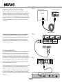
Introduction
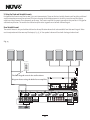
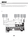
Congratulations on your purchase of the NuVo Essentia System. Essentia brings the best of today's digital technology to a true wholehome audio system. Listening to multiple audio sources from independent zones throughout the home has never been easier or more
affordable.
The elegant keypads allow independent selection of up to six different audio sources from up to twelve zones in the home.Each ship
including white, almond, ivory and black inserts and trim plates to match a variety of decorating choices. Generation D digital
amplification provides clear, precise digital sound to each zone without the heat generated by traditional analog amplification. The
integrated infrared repeater in each keypad means you can control all of your audio sources wirelessly from any zone of your home.
Enjoying quality audio throughout the home is simple and affordable with Essentia. This installation manual is designed to provide a
sequential, step-by-step guide to making full use of the many features and capabilities of the Essentia System.
Package Contents:
E6DMS-DC Main System
1 NV-E6DM2
Six-Source, Six-Zone Amplifier
6 NV-E6DKP-DC Decora®* style Zone Controller Keypads
including white, almond, ivory and black.
1 NV-LRC1
Learning Remote Control
1 NV-E6DEZP
Decora® EZ Port Multi-port connection hub
1 NV-NEC
Network connection cable
6 NV-VEC
IR emitters with feedback LED
1 NV-PC1
IEC 3-wire power cable
Zone/Room 1
Zone/Room 2
VOLUME
E6DXS-DC Expander System
1 NV-E6DMS
Six-Source, Six-Zone Amplifier
6 NV-E6DKP-DC Decora® style Zone Controller Keypads
including white, almond, ivory and black
1 NV-LRC1
Learning Remote Control
1 NV-SRC 1
Source Link Cable
1 NV-DNK1
Data Link Cable
1 NV-PC1
IEC 3-wire power cable
*Decora is a registered trademark of the Leviton Corp.
Zone/Room 3
Zone/Room 4
Zone/Room 5
Zone/Room 6
VOLUME
VOLUME
VOLUME
VOLUME
VOLUME
MUTE
MUTE
MUTE
MUTE
MUTE
MUTE
TNR1
TNR1
HD
SAT2
CD
TNR1
CD
TNR1
CD
TNR1
TNR2
HD
TNR2
HD
TNR2
HD
TNR2
HD
SAT 1
SAT2
SAT 1
SAT2
SAT 1
SAT2
SAT 1
SAT2
TNR1
CD
TNR2
SAT 1
CD
CD
TNR2
HD
SAT 1
SAT2
EZ Port Cat-5
connection
C C C
C C
C C C
C C
C C C
C C
C C C
C C
C C C
C C
C C C
C C
C C C
C C
C C C
C C
C C C
C C
C C C
C C
C C C
C C
C C C
C C
C C C
C C
C C C
MODEL NV-P2100
HIGH EFFICIENCY 200 WATT
STEREO AMPLIFIER
60HZ 250 WATTS
120V
NuVo Technologies Cincinnati Ohio. USA
AUDIO
Single Network cable
connection to the
Essentia Amplifier
SPEAKER
CONTROL
CONTROL
USE ONLY WITH 250V FUSE
L
SENSITIVITY
OdBV = 1.0RMS
INPUT
2
LEFT
0
POWER
MODE
ON/OFF SWITCH
AUDIO AC/DC
RIGHT
0
VOLTAGE UNIT
TRIGGER ON
3-30 VOLTS
AC OR DC
+12VDC
100mA
OUTPUT POWER
8 OHM: 70W X 2
4 OHM: 100W X 2
R
-12
+6
INPUT
VARIABLE
OUTPUT
VARIABLE
OUTPUT
OUTPUT POWER
TIP=L
RING=R
2
FIXED
OUTPUT
ZONE 2
3
4
5
VARIABLE
OUTPUT
OUTPUT POWER
TIP=L
RING=R
20W/6OHM X2
FIXED
OUTPUT
ZONE 1
1
VARIABLE
OUTPUT
OUTPUT POWER
TIP=L
RING=R
20W/6OHM X2
FIXED
OUTPUT
ZONE 3
6
20W/6OHM X2
VARIABLE
OUTPUT
OUTPUT POWER
TIP=L
RING=R
20W/6OHM X2
1
1
3
20W/6OHM X2
FIXED
OUTPUT
ZONE 6
ZONE 5
CONNECT TO
NV-E6DX
Essentia D
V.II
OUTPUT POWER
TIP=L
RING=R
20W/6OHM X2
FIXED
OUTPUT
ZONE 4
-12
VARIABLE
OUTPUT
OUTPUT POWER
TIP=L
RING=R
FIXED
OUTPUT
+6
OUTPUT
1
5
3
5
SYS ON
SUM1
CONNECT TO
NV-E6DEZP
USE NV-NC1
CABLE
USE NV-SLC1
CABLE
1
2
3
4
5
SOURCE INPUTS
Source 1
Tuner 1
Audio
Out
Source 2
Tuner 2
5
6
2
4
2
6
4
RS-232
USE ONLY WITH 250V FUSE
PROGRAM
6
SUM2
CONNECT TO
NV-E6DX
MODEL NV-E6DM2
SIX SOURCE SIX ZONE
AUDIO DISTRIBUTION SYSTEM
120V
60Hz 500W
NuVo Technologies Hebron KY USA
USE NV-SLC1
CABLE
www.nuvotechnologies.com
R
EXT. MUTE
US
C
SOURCE LINK
Source 3
Tuner 3
Audio
Out
ZONE TRIGGER OUTPUTS
Audio
Out
Source 4
CD 1
EMITTER OUTPUTS
SYSTEM
Source 5
CD 2
NETWORK
DIGITAL LINK
3033118
Source 6
Sat.
3
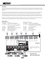
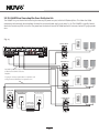
Diagram shown with optional NuVo
NV-P2100 auxiliary amplifier powering
zone 6.
CONFORMS TO
UL STD.6500
CERTIFIED TO
CAN/CSA STD.E60065
Audio
Out
Audio
Out
FUSE:T5 A
Audio
Out
Essentia D
Wiring Diagram
POWER
STAND BY
ZONE 1
ZONE 2
ZONE 3
ZONE 4
ZONE 5
ZONE 6
V.II
1
3
2
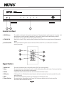
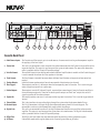
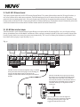
Essentia Front Panel
1. POWER Button:
2. STAND BY LED:
3. Zone Status LED's:
The amplifier is designed to be turned on and remain on. The power button supplies power to the system. Each
zone can then be turned on or off independently. The amplifier should be turned on before any external
connections are made. This activates internal protective circuitry.
When lit, this blue LED (light-emitting diode) indicates that the amplifier is plugged into an AC power outlet
source.
These LED's indicate the power status of each zone. When a zone LED is lit, it indicates that the zone is
currently turned on.
1
VOLUME
2
MUTE
TNR1
6
CD
TNR2
HD
SAT 1
SAT2
3
4
5
Keypad Features
1. Volume Level
2. Power
3. Volume
4. IR Receiver
5. Mute
6. Source Selection
The level of the zone volume is indicated by these LEDs (light-emitting diodes).
The power button turns that keypad's zone on and off independently of the other zones. Pressing and holding
the power button turns all zones off simultaneously.
Independent audio volume level for each zone is controlled with these buttons.
Each keypad has an IR (infrared) receiver located under the volume button for wireless control of the audio
source equipment.
The mute button temporarily silences any audio playing in that keypad's zone.
The source buttons independently select any of the six sources connected to the Essentia amplifier.
The selected source button will remain lit.
4
VARIABLE
OUTPUT
VARIABLE
OUTPUT
OUTPUT POWER
TIP=L
RING=R
FIXED
OUTPUT
2
4
5
20W/6OHM X2
FIXED
OUTPUT
ZONE 2
3
VARIABLE
OUTPUT
OUTPUT POWER
TIP=L
RING=R
20W/6OHM X2
FIXED
OUTPUT
ZONE 1
1
VARIABLE
OUTPUT
OUTPUT POWER
TIP=L
RING=R
20W/6OHM X2
ZONE 3
6
VARIABLE
OUTPUT
VARIABLE
OUTPUT
OUTPUT POWER
TIP=L
RING=R
OUTPUT POWER
TIP=L
RING=R
20W/6OHM X2
FIXED
OUTPUT
FIXED
OUTPUT
ZONE 4
1
1
3
20W/6OHM X2
FIXED
OUTPUT
Essentia D
V.II
ZONE 6
ZONE 5
CONNECT TO
NV-E6DX
OUTPUT POWER
TIP=L
RING=R
20W/6OHM X2
5
1
3
PROGRAM
5
SUM1
SYS ON
2
3
4
5
SOURCE INPUTS
1
CONNECT TO
NV-E6DEZP
USE NV-NC1
CABLE
USE NV-SLC1
CABLE
1
5
6
2
4
6
2
4
RS-232
6
SUM2
CONNECT TO
NV-E6DX
MODEL NV-6DM2
SIX SOURCE SIX ZONE
AUDIO DISTRIBUTION SYSTEM
120V
60Hz 500W
www.nuvotechnologies.com
EXT. MUTE
R
US
C
SOURCE LINK
2
EMITTER OUTPUTS
ZONE TRIGGER OUTPUTS
3 4
5
6
7
SYSTEM
NETWORK
DIGITAL LINK
FUSE:T5 A
NuVo Technologies Hebron KY USA
USE NV-SLC1
CABLE
3033118
CONFORMS TO
UL STD.6500
CERTIFIED TO
CAN/CSA STD.E60065
8 9 10 11 12
13
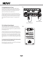
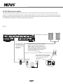
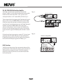
Essentia Back Panel
1. Audio Source Inputs: The Essentia amplifier accepts up to six audio sources. A source consists of any audio component capable
of supplying a line level signal.
This multi-pin connection is used to transfer the audio information from the Essentia main amplifier to the
2. Source Link:
expander amplifier. This output is used to expand the system to twelve zones. The source link connection
cable is provided with the Essentia D Expander package.
The variable lineout is intended for zones where additional amplification is needed and the Essentia keypad
3. Variable Lineout:
is used to control the volume of all the speakers in that zone.
The fixed lineout is intended for zones where additional amplification and separate volume control are
4. Fixed Lineout:
needed.
Individual stereo speaker outputs for each zone provide 20 watts output per channel.
5. Speaker Outputs:
These outputs provide a 12-volt output when the corresponding zone is turned on. This is used to trigger
6. Zone Triggers:
external equipment specific to a given zone.
These outputs transfer IR (infrared) signals, repeated from a zone keypad, from the Essentia amplifier to
7. Emitter Outputs:
the audio source equipment. There are six source specific outputs and two “sum” output that sends IR
signals regardless of the selected source.
This output provides a constant 12-volt output when any zone is turned on. This is used to trigger external
8. System On:
devices.
This is designed to mute any audio playing through the system when the phone or doorbell rings.
9. External Mute:
This RJ-45 connection is the input for all zone information coming from the Essentia keypads. The
10. Network Input:
connection is made using the Network Cable supplied with the package.
This multi-pin connection transfers all the digital information from the main amplifier to the expander
11. Digital Link:
amplifier. This output is used to expand the system from six to twelve zones. The Digital Link connection
cable is provided with the Essentia D Expander package.
The RS232 serial port allows two-way communication for control by a home automation system.
12. RS232 Port:
A detachable power cable supplies power to the Essentia System from any AC outlet.
13. AC Power:
5
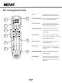
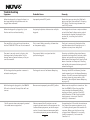
LRC1 Learning Remote Control
1. Setup:
1
1
4
2
7
3
2. Whole-Home Control: This section automatically performs the
basic Essentia keypad functions.
SOURCE
5
6
3. Transport Buttons:
M
WHOLE-HO E CONTROL
VOL-
The setup button is used to place the
remote control in program/learn mode.
VOL+
MUTE
ON/OFF
2
The transport buttons perform basic
source specific functions, such as play,
stop, pause, forward and reverse.
3
4. Video Source Control: These buttons are typically used by
video equipment for menu navigation
and selection.
4
5. Source Volume:
This is source specific volume control,
such as a TV or stereo receiver. This is not
used for NuVo zone volume.
6. Numeric Buttons:
These buttons provide source specific
direct numeric access.
7. Power Button:
This power button is for source specific
power on and off. It is not for NuVo zone
on and off.
8
5
6
M1
M2
M3
M4
M5
M6
M7
M8
9
8. Channel up and down: This button provides source specific
channel scrolling.
9. Macro Buttons:
NV-LRC1
6
These buttons do not perform a given
source function. They can be used for
programming multiple function macro
commands.
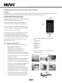
Installing the Essentia System in Your Home
I. Prewire
Gro
und
IR
TX
Gro
u
Con nd
tr
Con ol Da
ta
tr
IR ol Da BusAct
ta B
us+
Gro ive
u
+12 nd
VP
ow
er
The Essentia System uses CAT5 cable for keypad control and either two or four-conductor 16-gauge speaker wire. All the wire is
“homerun” from each zone to the location of the Essentia amplifier and Audio Source equipment.
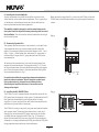
Complete CAT5 Crimping Instructions
The NuVo audio systems require CAT5, unshielded, twisted
pair (UTP), for communication between the
keypads/Display Pads and the main amplifier unit. Each
end of the wire is terminated with an RJ45 connector.
Top view with
tab down.
The Essentia System can accommodate 2,000 total feet of
CAT5 cable. For the most reliable operation, it is best that
no single run of CAT5 exceeds 250 feet.
1 2 3 4 5 6 7 8
The correct wiring scheme for the CAT5 cable is standard
EIA/TIA 568A. Properly terminating the CAT5 cable is
crucial for the operation of the system. It is very important
to use a good quality crimp tool, and test each end to end
run with a CAT5 wire tester to insure that your system
operates flawlessly, fig.1.
Pair 2
Pair 1
Pair 3
Pair 4
Wires insert from
this end.
Fig. 1: EIA 568A wiring scheme for CAT5 Cable
Pin #
1. Green Stripe
2. Green
3. Orange Stripe
4. Blue
5. Blue Stripe
6. Orange
7. Brown Stripe
8. Brown
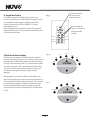
Step-by-Step Crimping Instructions:
1.
Strip a 2 to 3 inch portion of the insulation,
exposing the 4 twisted pairs.
2.
Untwist the wires and fan them out
individually. Arrange the wires into the
correct color scheme as shown in Fig. 1.
3.
Flatten the wires in their correct order, and trim
them evenly across the top. Most crimp tools have
a wire trimmer built-in. It is best to trim the wires
to about ½” in length.
4.
While holding the wires flat between your thumb
and forefinger, insert the wires into the RJ45
connector, so each is in its own slot. Push the wire
into the RJ45, so all 8 conductors touch the end of
the connector. The insulation jacket should
extend beyond the crimp point of the RJ45.
5.
Insert the RJ45 into the crimp tool receptacle and
squeeze the tool firmly. Note that a ratchet type
tool should tighten down until it no longer clicks.
6.
The RJ45 should be firmly crimped to the CAT5
insulation. It is necessary that the color scheme
be repeated identically on each end of the wire.
Note: Colors listed as “stripe” are a white wire
with a colored stripe.
7
Step 1
Step 2
Step 3
Step 4
Step 5
Step 6
II. Installing the Essentia Amplifier
System setup works best when the amplifier is placed in the
same location as the audio source equipment. This is typically in
an audio rack, entertainment center or a closet dedicated to
housing the home audio/video equipment.
Once you have plugged the Cat-5 wires into the EZ Port, screw the
EZ Port into its construction bracket using the supplied mounting
screws.
The amplifier should be plugged in and the power button on the
front panel should be depressed before proceeding with the rest of
the installation. This activates the internal protective circuitry of
the Essentia System.
Fig. 2
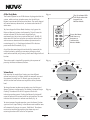
II. Terminating Speaker Wire
The speaker wire for each zone is terminated in a standard Eurostyle connector that plugs into each zone specific amplified
output. The common speaker termination scheme is Left - Left +,
Right - Right +. Either two or four-conductor 16-guage wire is
recommended. Larger than 14-guage wire will not fit into the
euro connector.
To terminate the speaker wire, strip back the outer jacket and
expose the inner conductors. Strip approximately 1/4” (4 mm)
of the insulation from the inner conductors exposing the copper
wire. Place the exposed wire in the euro connector and tighten
the screw down terminals, fig. 2.
-
LEFT
Be careful not to allow the exposed wire from each conductor to
touch the adjacent conductor. This will short the speaker input.
Each speaker output is designed for two 8-Ohm speakers.
Overloading the amplifier could cause it to overheat and do
damage to the output.
Fig. 3
III. Installing the NV-E6DEZP EZ Port
The EZ Port is a multi-connection hub designed to accept all the
CAT5 wires from the keypads in the system. The location of the EZ
Port should be determined by the location of the Essentia
amplifier. It is best to place in the wall behind the amplifier that
would be easily accessible if necessary.
The EZ Port fits easily in any dual-gang size construction bracket
with an open back. These are often referred to as “mud rings”.
Simply plug the terminated CAT5 wires into any of the sixteen
available jacks on the back of the EZ Port, Fig. 3. The order in
which the individual CAT5 wires are plugged is in not important,
although it is strongly recommended that you label the CAT5 with
the appropriate zone number for future reference.
8
-
LEFT RIGHT RIGHT
+
+
Fig. 4
IV. Connecting the EZ Port to the Essentia amplifier
When the EZ Port is installed in the wall the only part visible
should be the faceplate and a single RJ45 jack. The supplied preterminated network cable can then be plugged into the jack on
the EZ Port and into the network connection on the back of the
Essentia amplifier, Fig. 4. Any CAT5 cable terminated using 568A
or 568B network wiring will suffice should you need a longer
connection.
EZ Port (front)
Essentia Network
Connection
PROGRAM
SYS ON
CONNECT TO
NV-E6DEZP
USE NV-NC1
CABLE
NV-E6D EZ Port
Model NV-E6DEZP
CONNECT TO
NV-E6DX
USE NV-SLC1
CABLE
EXT. MUTE
SYSTEM
Connect to NV-E6DM
Audio Distribution Amplifier
NETWORK
DIGITAL LINK
Network Cable
Fig. 5
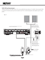
V. Attaching Audio Source Equipment to the Essentia Amplifier
Each piece of audio source equipment is connected to the
Essentia amplifier with standard stereo RCA cables. Attach the
RCA cable to the corresponding audio output on the source
equipment and to the desired source input on the back of the
Essentia amplifier, Fig. 5.
VARIABLE
OUTPUT
VARIABLE
OUTPUT
OUTPUT POWER
TIP=L
RING=R
FIXED
OUTPUT
2
OUTPUT POWER
TIP=L
RING=R
20W/6OHM X2
FIXED
OUTPUT
ZONE 1
1
VARIABLE
OUTPUT
OUTPUT POWER
TIP=L
RING=R
20W/6OHM X2
ZONE 2
3
4
5
FIXED
OUTPUT
ZONE 3
6
CONNECT TO
NV-E6DX
USE NV-SLC1
CABLE
1
2
3
4
5
Source 1
Tuner 1
VI. Connecting the IR Emitters
IR commands for the source equipment are transferred from the
Essentia amplifier to the source equipment via mini IR mouse
emitters. Six of these are supplied with your Essentia System.
The emitter is plugged into the corresponding source IR output
on the Essentia and then placed over the IR receiver window on
the source component, fig. 6. The IR outputs are individually
routed to sources 1-6 allowing IR commands from the chosen
source to only control that source.
Fig. 6
The two SUM outputs will flash any IR command that is sent from
any of the zones. This is used to connect the NuVo T2 Tuner,
which has a single IR direct input to control both tuners to the
Essentia System or an IR blaster designed to flash IR commands
to a variety of components. This is done by plugging a single
mono 1/8” patch cable into the SUM IR output and into the Direct
IR input.
9
6
SOURCE LINK
SOURCE INPUTS
Audio
Out
20W/6OHM X2
Fig. 7
VII. Expanding Essentia to 12 Zones
Six additional listening zones can be added to the Essentia
System using the Essentia Expander package. The expansion is
easily done using the Source Link and Digital Link multi-pin
outputs on the Essentia main amplifier, Fig. 7.
VARIABLE
OUTPUT
VARIABLE
OUTPUT
OUTPUT POWER
TIP=L
RING=R
VARIABLE
OUTPUT
OUTPUT POWER
TIP=L
RING=R
20W/6OHM X2
FIXED
OUTPUT
ZONE 71
VARIABLE
OUTPUT
OUTPUT POWER
TIP=L
RING=R
20W/6OHM X2
FIXED
OUTPUT
20W/6OHM X2
FIXED
OUTPUT
ZONE 8
VARIABLE
OUTPUT
ZONE 9
VARIABLE
OUTPUT
OUTPUT POWER
TIP=L
RING=R
OUTPUT POWER
TIP=L
RING=R
20W/6OHM X2
FIXED
OUTPUT
ZONE 10
CONNECT TO
NV-E6DM2
OUTPUT POWER
TIP=L
RING=R
20W/6OHM X2
FIXED
OUTPUT
1
8
7
20W/6OHM X2
FIXED
OUTPUT
ZONE 12
ZONE 11
9
CONNECT TO
NV-E6DM2
USE NV-SLC1
CABLE
5
SOURCE LINK
VARIABLE
OUTPUT
VARIABLE
OUTPUT
OUTPUT POWER
TIP=L
RING=R
The necessary cables for this are supplied with the Expander
package. No other connections are necessary with the exception
of the AC power cord and the additional speaker terminations.
The additional CAT5 wires for the zones 7-12 plug into the EZ
Port.
1
2
VARIABLE
OUTPUT
FIXED
OUTPUT
ZONE 2
3
4
5
ZONE 3
6
20W/6OHM X2
VARIABLE
OUTPUT
OUTPUT POWER
TIP=L
RING=R
20W/6OHM X2
OUTPUT POWER
TIP=L
RING=R
20W/6OHM X2
FIXED
OUTPUT
ZONE 4
1
2
20W/6OHM X2
FIXED
OUTPUT
Essentia D
V.II
ZONE 6
ZONE 5
1
CONNECT TO
NV-E6DX
DIGITAL LINK
3
1
2
2
3
4
5
3
SUM1
SYS ON
5
SOURCE LINK
SOURCE INPUTS
CONNECT TO
NV-E6DEZP
USE NV-NC1
CABLE
6
4
5
6
ZONE TRIGGER OUTPUTS
4
5
US
C
3033118
CONFORMS TO
UL STD.6500
CERTIFIED TO
CAN/CSA STD.E60065
RS-232
PROGRAM
USE NV-SLC1
CABLE
1
FUSE:T5 A
www.nuvotechnologies.com
R
VARIABLE
OUTPUT
OUTPUT POWER
TIP=L
RING=R
FIXED
OUTPUT
60Hz 500W
NuVo Technologies Hebron KY USA
12
11
VARIABLE
OUTPUT
OUTPUT POWER
TIP=L
RING=R
20W/6OHM X2
FIXED
OUTPUT
ZONE 1
10
ZONE TRIGGER OUTPUTS
OUTPUT POWER
TIP=L
RING=R
20W/6OHM X2
FIXED
OUTPUT
MODEL NV-6DX
SIX SOURCE SIX ZONE
AUDIO DISTRIBUTION SYSTEM
120V
USE NV-SLC1
CABLE
6
SUM2
CONNECT TO
NV-E6DX
MODEL NV-6DM2
SIX SOURCE SIX ZONE
AUDIO DISTRIBUTION SYSTEM
120V
60Hz 500W
www.nuvotechnologies.com
R
EXT. MUTE
US
C
EMITTER OUTPUTS
SYSTEM
NETWORK
FUSE:T5 A
NuVo Technologies Hebron KY USA
USE NV-SLC1
CABLE
DIGITAL LINK
3033118
CONFORMS TO
UL STD.6500
CERTIFIED TO
CAN/CSA STD.E60065
Data Link Cable
Source Link Cable
VIII. Installing the Essentia Keypads
Fig. 8
01 2
BC D
EF
3456
You are now ready to install the keypads and complete the
Essentia installation. This is easily done using a rotary switch
located on the back of the keypad to set a specific zone address
for each keypad, Fig. 8.
789 A
Local Source
Zone
Address
The switch requires the use of a small flat screwdriver and is set
by turning the arrow insert on the switch to the appropriate zone
number. Zones 1-12 are set by using switch positions 1-C (note
that zones 10, 11 and 12 are denoted by A, B and C respectively).
Switch positions D, E, F and 0 are for additional keypads in zones
1-4.
Essentia Keypad
Model NV-E6DKP-DC
WARNING:
Use only with
NuVo Essentia System
AVIS:
Utiliser uniquement avec
NuVo Essentia System
NuVo Technologies LLC Hebron, Kentucky USA
www.nuvotechnologies.com
Network
Connection
It is important to note that the keypads will not function properly
unless each has its own unique zone address.
Once each keypad’s zone address is set, the CAT5 can be plugged
in and the keypad installed in the wall.
10
The volume indicator
LED indicates the
function being set.
Fig. 9
IX. Keypad Zone Settings
Each Essentia keypad has the ability to set specific zone
functions. These are bass and treble EQ, source grouping, all on
(party mode) and volume reset. Each of these functions is
accessed by pressing the MUTE and SOURCE 1-5 buttons
simultaneously, fig. 9.
While the keypad is in the function set mode, the appropriate
source button with flash. To return to normal zone control, press
the flashing source button.
Press the Mute and
Source 1-5 buttons to
initiate each zone
function.
VOLUME
MUTE
To change bass response, press the Mute button and Source 1
button simultaneously. Adjust the bass level up or down by using
the Volume Up and Volume Down buttons. The volume indicator
LEDs will indicate the output level, fig. 8. Adjust treble response
using the same process. This is accessed by pressing the Mute
and Source 2 buttons. Once the desired setting is made, press
the Source button again to return the keypad to normal
operation.
Source 2
TNR2
HD
Source 4
SAT 1
SAT2
TNR1
Source 3
Source 5
Fig.10
EQ Control and Source Grouping
CD
Source 1
-4 dB
FLAT
+4 dB
-6 dB
+6 dB
-8 dB
+8 dB
VOLUME
Source grouping is a feature that allows multiple zones in an
open living space to always share the same source selection but
still retain individual volume and on/off control. This is achieved
by pressing Mute and Source 3. Volume Up enables the group
function, and Volume Down disables the group function and
causes the keypad to operate independently of all other groups,
fig. 10.
Fig. 11
Group Disabled
Group Enabled
VOLUME
11
Fig. 12
All On/Party Mode
The lit volume LED
will flash when the
keypad is in
Master Mode.
The Essentia System has an All On feature. Any keypad within the
system, which can be up to twelve zones, has the ability to
become a master control for the entire house. The master keypad
will control zone on, volume level, and source selection for all
other zones.
To place a keypad in Master Mode function, simply press the
Mute and Source 4 buttons simultaneously. This will cause the
volume indicator LED for that zones keypad to flash
continuously and adjust to a preset volume level (-60 dB). All
other zones will then turn on to the same relative volume level
and increase or decrease with the volume adjustment on the
master keypad, fig. 12. Each keypad volume LED indicates a
preset meter level threshold, fig. 13.
VOLUME
Press the Mute
and Source 4
buttons to
initiate the
Master Mode.
MUTE
TNR1
CD
TNR2
HD
SAT 1
SAT2
Source 4
Any of the other zone keypads have the ability to override the
master function by selecting a new source, changing a local
zones volume control, or by turning a local zones keypad off and
back on.
The master mode is turned off by repeating the sequence of
pressing the Mute and Source 4 buttons.
Fig. 13
-38 to -29 dB
-28 to -19 dB
-18 to -13 dB
-54 to -39 dB
-12 to -7 dB
-78 to -55 dB
-6 to 0 dB
VOLUME
Volume Reset
Each zone has the capability of turning on at two different
volume level settings. At factory default the zone will turn on at
the previous listening level. If desired, you can change that
default to a low level volume reset regardless of the previous
level.
To change the zone to volume reset mode, press the Mute and
Source 5 buttons simultaneously. The Source 5 button will begin
flashing. The volume LED will first appear at the far left
indicating no volume reset. Pushing the Volume Up button will
cause the volume LED to move to the far right position. This now
indicates that the zone is in volume reset mode, fig. 14.
Fig. 14
Volume Reset Off
Volume Reset On
VOLUME
To return to normal keypad operation, press the Source 5 button
again and it will stop flashing. In the volume reset mode the zone
will automatically turn on at a preset -60 dB level. The volume
reset can be turned off by repeating the above steps and
returning the volume LED to the far left position.
12
X. Using the Fixed and Variable Lineouts
Each zone of the Essentia amplifier has two 3.5mm mini stereo outputs. These are fixed and variable lineouts used for adding additional
amplification when necessary for each zone. A distinct advantage to the NuVo equipment is the ability to use the amplified output,
variable and fixed lineouts all simultaneously on all zones. The Essentia amplifier has zone trigger outputs that provide a 12V trigger for
additional amplification. This enables the attached amplifier to be triggered on and off with the zone keypad.
Zone Variable Lineout
The variable lineout is designed to allow additional audio amplification volume level to be controlled from that zone’s keypad. When
used in conjunction with the zone amplified output, fig. 15, all the speaker’s volume will track with the keypad volume level.
Fig. 15
Zone/Room 1
VOLUME
MUTE
TNR1
C C C
C C C
C C C
C C C
C C C
C C C
C C C
C C C
C C C
C C C
C C C
C C C
C C C
C C C
C C C
C C C
C C C
C C C
C C C
C C C
C C C
C C C
C C C
C C C
C C C
C C C
C C C
C C C
C C C
CD
TNR2
HD
SAT 1
SAT2
The Zone keypad controls the audio volume.
MODEL NV-P2100
HIGH EFFICIENCY 200 WATT
STEREO AMPLIFIER
60HZ 250 WATTS
120V
Diagram shown using the NuVo P2100 amplifier
NuVo Technologies Cincinnati Ohio. USA
AUDIO
SPEAKER
CONTROL
CONTROL
USE ONLY WITH 250V FUSE
L
SENSITIVITY
OdBV = 1.0RMS
INPUT
2
POWER
MODE
ON/OFF SWITCH
AUDIO AC/DC
RIGHT
0
LEFT
0
VOLTAGE UNIT
TRIGGER ON
3-30 VOLTS
AC OR DC
OUTPUT POWER
+12VDC
100mA
8 OHM: 70W X 2
4 OHM: 100W X 2
R
-12
+6
INPUT
VARIABLE
OUTPUT
VARIABLE
OUTPUT
OUTPUT POWER
TIP=L
RING=R
FIXED
OUTPUT
2
ZONE 2
3
4
5
FIXED
OUTPUT
ZONE 3
6
VARIABLE
OUTPUT
OUTPUT POWER
TIP=L
RING=R
20W/6OHM X2
FIXED
OUTPUT
ZONE 1
1
VARIABLE
OUTPUT
OUTPUT POWER
TIP=L
RING=R
20W/6OHM X2
20W/6OHM X2
VARIABLE
OUTPUT
OUTPUT POWER
TIP=L
RING=R
20W/6OHM X2
FIXED
OUTPUT
OUTPUT POWER
TIP=L
RING=R
20W/6OHM X2
FIXED
OUTPUT
ZONE 4
1
1
3
20W/6OHM X2
FIXED
OUTPUT
Essentia D
V.II
ZONE 6
ZONE 5
CONNECT TO
NV-E6DX
-12
MODEL NV-6DM
SIX SOURCE SIX ZONE
AUDIO DISTRIBUTION SYSTEM
VARIABLE
OUTPUT
OUTPUT POWER
TIP=L
RING=R
+6
OUTPUT
5
1
3
2
3
4
5
SUM1
SYS ON
Source 1
Tuner 1
CONNECT TO
NV-E6DEZP
USE NV-NC1
CABLE
5
6
2
4
6
2
4
6
SUM2
CONNECT TO
NV-E6DX
MODEL NV-6DM2
SIX SOURCE SIX ZONE
AUDIO DISTRIBUTION SYSTEM
120V
60Hz 500W
ZONE TRIGGER OUTPUTS
Audio
Out
13
EMITTER OUTPUTS
USE NV-SLC1
CABLE
www.nuvotechnologies.com
R
EXT. MUTE
SYSTEM
NETWORK
FUSE:T5 A
NuVo Technologies Hebron KY USA
US
C
SOURCE LINK
SOURCE INPUTS
USE ONLY WITH 250V FUSE
PROGRAM
5
USE NV-SLC1
CABLE
1
RS-232
DIGITAL LINK
3033118
CONFORMS TO
UL STD.6500
CERTIFIED TO
CAN/CSA STD.E60065
Zone Fixed Lineout
In some zone applications, it is more advantageous to have a separate volume control on the additional speakers being driven by an
additional amplifier. This is common with outdoor zones. The fixed lineout offers the capability to add amplification, but the audio signal
is not affected by the zone keypad volume level. Therefore, it requires a separate volume control for those speakers, fig. 16.
Fig. 16
Zone/Room 1
VOLUME
MUTE
TNR1
C C C
C C C
C C C
C C C
C C C
C C C
C C C
C C C
C C C
C C C
C C C
C C C
C C C
C C C
C C C
C C C
C C C
C C C
C C C
C C C
C C C
C C C
C C C
C C C
C C C
C C C
C C C
C C C
C C C
CD
TNR2
HD
SAT 1
SAT2
Additional speakers are controlled by a separate
volume control.
MODEL NV-P2100
HIGH EFFICIENCY 200 WATT
STEREO AMPLIFIER
60HZ 250 WATTS
120V
NuVo Technologies Cincinnati Ohio. USA
Diagram shown using the NuVo P2100 amplifier
AUDIO
SPEAKER
CONTROL
CONTROL
USE ONLY WITH 250V FUSE
L
SENSITIVITY
OdBV = 1.0RMS
INPUT
2
POWER
MODE
ON/OFF SWITCH
AUDIO AC/DC
RIGHT
0
LEFT
0
VOLTAGE UNIT
TRIGGER ON
3-30 VOLTS
AC OR DC
OUTPUT POWER
+12VDC
100mA
8 OHM: 70W X 2
4 OHM: 100W X 2
R
-12
+6
INPUT
VARIABLE
OUTPUT
VARIABLE
OUTPUT
OUTPUT POWER
TIP=L
RING=R
FIXED
OUTPUT
2
ZONE 2
3
4
5
FIXED
OUTPUT
ZONE 3
6
VARIABLE
OUTPUT
OUTPUT POWER
TIP=L
RING=R
20W/6OHM X2
FIXED
OUTPUT
ZONE 1
1
VARIABLE
OUTPUT
OUTPUT POWER
TIP=L
RING=R
20W/6OHM X2
20W/6OHM X2
VARIABLE
OUTPUT
OUTPUT POWER
TIP=L
RING=R
20W/6OHM X2
FIXED
OUTPUT
OUTPUT POWER
TIP=L
RING=R
20W/6OHM X2
FIXED
OUTPUT
ZONE 4
1
1
3
20W/6OHM X2
FIXED
OUTPUT
Essentia D
V.II
ZONE 6
ZONE 5
CONNECT TO
NV-6DX
-12
VARIABLE
OUTPUT
OUTPUT POWER
TIP=L
RING=R
+6
OUTPUT
5
1
3
2
3
4
5
SUM1
SYS ON
Source 1
Tuner 1
CONNECT TO
NV-E6DEZP
USE NV-NC1
CABLE
5
6
2
4
6
2
4
6
SUM2
CONNECT TO
NV-E6DX
MODEL NV-6DM2
SIX SOURCE SIX ZONE
AUDIO DISTRIBUTION SYSTEM
120V
60Hz 500W
ZONE TRIGGER OUTPUTS
Audio
Out
14
EMITTER OUTPUTS
www.nuvotechnologies.com
R
EXT. MUTE
SYSTEM
NETWORK
FUSE:T5 A
NuVo Technologies Hebron KY USA
USE NV-SLC1
CABLE
US
C
SOURCE LINK
SOURCE INPUTS
USE ONLY WITH 250V FUSE
PROGRAM
5
USE NV-SLC1
CABLE
1
RS-232
DIGITAL LINK
3033118
CONFORMS TO
UL STD.6500
CERTIFIED TO
CAN/CSA STD.E60065
XI. The NV-LRC1 IR Remote Control
The Essentia System comes with the NV-LRC1 Learning Remote Control. This remote allows wireless control of all keypad functions, as
well as the functions of the audio source equipment. Each NuVo zone keypad has an IR receiver that captures the specific source
commands from any remote control and in turn sends the command ultimately to the appropriate source equipment. Embedded IR code
libraries makes use of the LRC1 with a large variety of audio and video equipment easy. For complete setup and functionality refer to the
User Guide included with the remote control. Additional remote controls are available from NuVo.
XII. NV-MI1 Mute Interface Adapter
The Mute Interface is used in conjunction with System Mute input in the back of the Essentia amplifier. It acts as a relay for a voltage
from up to two phone lines and two doorbell transformers. When a voltage is presented to the MI1 it then sends a contact closure to the
Essentia System, which in turn causes the system to mute momentarily. This is useful in allowing the telephone ring or doorbell to be
heard when audio is playing in any of the zones, Fig. 17.
Fig. 17
VARIABLE
OUTPUT
VARIABLE
OUTPUT
OUTPUT POWER
TIP=L
RING=R
TIP=L
RING=R
20W/6OHM X2
FIXED
OUTPUT
2
ZONE 2
3
L
R
1
4
3
ZONE 3
L
R
2
FIXED
OUTPUT
20W/6OHM X2
TIP=L
RING=R
VARIABLE
OUTPUT
OUTPUT POWER
VARIABLE
OUTPUT
OUTPUT POWER
20W/6OHM X2
TIP=L
RING=R
FIXED
OUTPUT
TIP=L
RING=R
20W/6OHM X2
FIXED
OUTPUT
ZONE 4
3
OUTPUT POWER
20W/6OHM X2
FIXED
OUTPUT
Essentia D
V.II
ZONE 6
ZONE 5
1
6
5
L
VARIABLE
OUTPUT
OUTPUT POWER
TIP=L
RING=R
20W/6OHM X2
FIXED
OUTPUT
ZONE 1
1
VARIABLE
OUTPUT
OUTPUT POWER
5
1
3
RS-232
USE CNLY WITH 250V FUSE
PROGRAM
5
SYS ON
SUM1
CONNECT TO
NV-E6DX
CONNECT TO
NV-E6DEZP
CONNECT TO
NV-E6DX
USE NV-SLC1
CABLE
USE NV-NC1
CABLE
USE NV-SLC1
CABLE
NETWORK
DIGITAL LINK
MODEL NV-6DM
SIX SOURCE SIX ZONE
AUDIO DISTRIBUTION SYSTEM
120V
60Hz 500W
FUSE:T5 A
NuVo Technologies Cincinnati Ohio USA
www.nuvotechnologies.com
R
4
SOURCE INPUTS
5
2
6
4
6
4
2
6
SUM2
EXT. MUTE
R
ZONE TRIGGER OUTPUTS
EMITTER OUTPUTS
SYSTEM
The MI1 connects to the NuVo amplifier using a standard
mono patch cable with a mini-plug on each end. Plug one
end into the EXT. MUTE input on the back of the
amplifier and the other end into the input on the front of
the Mi1.
CONFORMS TO
UL STD.6500
CERTIFIED TO
CAN/CSA STD.E60065
US
C
SOURCE LINK
3033118
The back of the MI1 will accept up to two AC or
DC voltages from two different doorbell chimes.
This connection is done with a two conductor
wire from the terminals on the doorbell chime to
the Doorbell A or Doorbell B inputs on the back
of the MI1. Polarity is not important for this
connection.
DOORBELL 1
A
B
MUTE INTERFACE
ADAPTER
NV-MI1
DOORBELL 2
A
B
CONNECT TO
MUTE INPUT
Connect to Telephone RJ-11
Line 1: Pins 3,4 Line 2: Pins 2,5
Model NV-MI1
Mute Interface Module
Up to two phone lines can be brought into
the RJ-11 connection on the back of the MI1.
The voltage from the phone ringer will
trigger the NuVo System to mute.
15
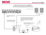
XIII. NV-LSA40 Local Source Amplifier
The LSA40 is 40 watt accessary amplifier that allows any line-level audio signal local to a zone to be amplified through that zone’s
speakers. It is designed to be used universally in a variety of applications, but as shown in fig. 18, it can be triggered on and off by any
zone keypad. When connected to the keypad, the user will listen to the NuVo audio system when the zone is turned on. When the zone is
off the LSA40 will automatically amplify any incoming local audio signal.
Fig. 18
2
ZONE 2
3
4
5
FIXED
OUTPUT
ZONE 3
6
VARIABLE
OUTPUT
OUTPUT POWER
TIP=L
RING=R
20W/6OHM X2
FIXED
OUTPUT
ZONE 1
1
VARIABLE
OUTPUT
OUTPUT POWER
TIP=L
RING=R
20W/6OHM X2
CONNECT TO
NV-E6DX
20W/6OHM X2
VARIABLE
OUTPUT
VARIABLE
OUTPUT
OUTPUT POWER
TIP=L
RING=R
OUTPUT POWER
TIP=L
RING=R
20W/6OHM X2
FIXED
OUTPUT
OUTPUT POWER
TIP=L
RING=R
20W/6OHM X2
FIXED
OUTPUT
ZONE 4
1
Essentia D
V.II
ZONE 6
ZONE 5
1
20W/6OHM X2
FIXED
OUTPUT
5
3
1
3
SUM1
SYS ON
USE NV-SLC1
CABLE
3
4
SOURCE INPUTS
5
6
SOURCE LINK
2
6
4
ZONE TRIGGER OUTPUTS
4
2
SUM2
6
CONNECT TO
NV-E6DEZP
CONNECT TO
NV-E6DX
MODEL NV-6DM2
SIX SOURCE SIX ZONE
AUDIO DISTRIBUTION SYSTEM
120V
60Hz 500W
USE NV-SLC1
CABLE
www.nuvotechnologies.com
R
EXT. MUTE
SYSTEM
NETWORK
FUSE:T5 A
NuVo Technologies Hebron KY USA
US
C
EMITTER OUTPUTS
Any NuVo System
zone output can be
wired to the LSA40
Local Source
Amplifier.
DIGITAL LINK
3033118
CONFORMS TO
UL STD.6500
CERTIFIED TO
CAN/CSA STD.E60065
A two conductor wire is used as a voltage
trigger from the LSA40 the NuVo zone
keypad. When the zone is turned on this
allows to NuVo system audio to pass to the
zone speakers. When the zone is turned off
the internal amplifier of the LSA40 is
automatically engaged.
Zone/Room 1
VOLUME
MUTE
TNR1
LSA40P Back
MODEL:NV-LSA40-DC
LOCAL SOURCE AMPLIFIER
+
-
Control
Voltage
28VDC
1.5A
IN
LSA40P Front
3033118
NT
DESIGNED IN USA
ER TEK
INPUT
+
-
EF
L+
LR+
R-
MADE IN CHINA
POWER
50 Watt AC
power adapter
supplied with
the LSA40P
16
01 2
3456
TO AMPLIFIER
LR+
The connection from the LSA40 to
the Essentia or Concerto keypads
is done using the provide two
prong plug.
TE RTEK
CM
L+
R-
I
2
TO SPEAKER
1
USE ONLY WITH 250V FUSE
PROGRAM
5
USE NV-NC1
CABLE
5
NuVo System zone speakers.
RS-232
BC D
VARIABLE
OUTPUT
OUTPUT POWER
TIP=L
RING=R
FIXED
OUTPUT
789 A
VARIABLE
OUTPUT
CD
TNR2
HD
SAT 1
SAT2
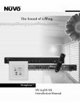
XIV. NV-LSA40PD Local Source Amplifier Power Distribution Hub
The LSA40PD is a great device for distributing the necessary DC power to up to 4 individual LSA40 amplifiers. This allows the LSA40
components to be remotely located without the need for an external power supply in the zone, fig. 19. The LSA40PD is typically located
where the Essentia amplifier is installed. The power from the head end to each of LSA40 locations is sent over standard 16 gauge speaker
wire.
Fig. 19
VOLUME
LSA40 Back
TIP=L
RING=R
20W/6OHM X2
FIXED
OUTPUT
3
L
4
ZONE 3
20W/6OHM X2
TIP=L
RING=R
OUTPUT POWER
L
L
TIP=L
RING=R
TIP=L
RING=R
20W/6OHM X2
FIXED
OUTPUT
3
OUTPUT POWER
20W/6OHM X2
FIXED
OUTPUT
Essentia D
V.II
ZONE 6
ZONE 5
1
6
5
OUTPUT POWER
20W/6OHM X2
FIXED
OUTPUT
ZONE 4
R
2
5
MODEL:NV-LSA40
LOCAL SOURCE AMPLIFIER
+
-
USE CNLY WITH 250V FUSE
L+
1
3
5
SUM1
SYS ON
CONNECT TO
NV-E6DX
CONNECT TO
NV-E6DEZP
CONNECT TO
NV-E6DX
USE NV-SLC1
CABLE
USE NV-NC1
CABLE
USE NV-SLC1
CABLE
NETWORK
DIGITAL LINK
MODEL NV-6DM2
SIX SOURCE SIX ZONE
AUDIO DISTRIBUTION SYSTEM
120V
60Hz 500W
L-
FUSE:T5 A
R+
www.nuvotechnologies.com
R
3
4
2
6
5
4
6
2
4
6
SUM2
EXT. MUTE
R
ZONE TRIGGER OUTPUTS
EMITTER OUTPUTS
SYSTEM
3033118
+
L+
LR+
R-
NuVo Technologies LLC Cincinnati, Ohio USA
www.nuvotechnologies.com
Designed In USA Made In China
CONFORMS TO
UL STD.6500
CERTIFIED TO
CAN/CSA STD.E60065
WIRE STRIP 5/16” (8MM)
US
C
SOURCE LINK
SOURCE INPUTS
HD
SAT2
RS-232
PROGRAM
R-
R
1
CD
SAT 1
VARIABLE
OUTPUT
TO AMPLIFIER
2
TIP=L
RING=R
20W/6OHM X2
ZONE 2
VARIABLE
OUTPUT
28VDC
1.5A
1
OUTPUT POWER
OUTPUT POWER
FIXED
OUTPUT
ZONE 1
VARIABLE
OUTPUT
TO
KEYPAD
OUTPUT POWER
TIP=L
RING=R
FIXED
OUTPUT
VARIABLE
OUTPUT
TO SPEAKER
VARIABLE
OUTPUT
VARIABLE
OUTPUT
MUTE
TNR1
TNR2
VOLUME
LSA40 Back
MUTE
TNR1
CD
TNR2
HD
SAT 1
SAT2
MODEL:NV-LSA40
LOCAL SOURCE AMPLIFIER
LR+
R-
+
L+
TO SPEAKER
TO AMPLIFIER
Any NuVo System zone output can
be wired to the LSA40 Local Source
Amplifier.
TO
KEYPAD
28VDC
1.5A
+
L+
LR+
R-
NuVo Technologies LLC Cincinnati, Ohio USA
www.nuvotechnologies.com
Designed In USA Made In China
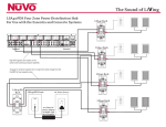
WIRE STRIP 5/16” (8MM)
16 gauge 2 conductor speaker wire is required to send
voltage from the LSA40PD to four separate zones.
VOLUME
LSA40 Back
MUTE
TNR1
CD
TNR2
HD
SAT 1
SAT2
MODEL:NV-LSA40
LOCAL SOURCE AMPLIFIER
R-
L+
TO SPEAKER
TO AMPLIFIER
LR+
+
-
TO
KEYPAD
28VDC
1.5A
+
L+
LR+
R-
NuVo Technologies LLC Cincinnati, Ohio USA
www.nuvotechnologies.com
Designed In USA Made In China
LSA40PD
Back
WIRE STRIP 5/16” (8MM)
LSA40PD Front
AC Power Source
VOLUME
LSA40 Back
ZONE 4
+
-
DESIGNED IN USA
MADE IN CHINA
TE RTEK
NT
I
IN
CM
D
3033118
ER TEK
POWER
200 Watt AC
power adapter
included with
the LSA40PD
MODEL:NV-LSA40
LOCAL SOURCE AMPLIFIER
R+
R-
TO AMPLIFIER
L-
28VDC
1.5A
+
L+
TO
KEYPAD
ZONE 2
ZONE 3
+
-
TO SPEAKER
ZONE 1
+
-
MUTE
TNR1
MODEL:NV-LSA40PD-DC
LOCAL SOURCE AMPLIFIER
28VDC 5A
+
-
+
L+
LR+
R-
NuVo Technologies LLC Cincinnati, Ohio USA
www.nuvotechnologies.com
Designed In USA Made In China
WIRE STRIP 5/16” (8MM)
17
CD
TNR2
HD
SAT 1
SAT2
XV. NV-LSI12 Local Source Interrupt
A lower cost alternative to the LSA40 is the LSI12. This is a non-amplified local source interrupt. It is installed in the same way the LSA40
is installed, but the incoming local signal must be amplified, fig 20. This is a useful accessory where a local amplified signal is already
present.
Fig. 20
The connection from the LSI12 is
done with the provided two prong
plug. Make sure that red is positive
and black is negative when splicing
the two conductor wire from the LSI12.
The selected zone speaker output of the Essentia or Simplese
amplifier is wired directly to the LSI12.
4
5
ZONE 3
6
VARIABLE
OUTPUT
VARIABLE
OUTPUT
OUTPUT POWER
TIP=L
RING=R
OUTPUT POWER
TIP=L
RING=R
20W/6OHM X2
FIXED
OUTPUT
ZONE 4
1
3
20W/6OHM X2
FIXED
OUTPUT
ZONE 6
ZONE 5
1
Essentia D
V.II
OUTPUT POWER
TIP=L
RING=R
20W/6OHM X2
FIXED
OUTPUT
5
1
3
2
3
4
SOURCE INPUTS
5
SYS ON
SUM1
SOURCE LINK
CONNECT TO
NV-E6DEZP
USE NV-NC1
CABLE
5
6
2
4
6
ZONE TRIGGER OUTPUTS
2
4
USE ONLY WITH 250V FUSE
PROGRAM
5
USE NV-SLC1
CABLE
1
RS-232
SUM2
6
EMITTER OUTPUTS
CONNECT TO
NV-E6DX
60Hz 500W
www.nuvotechnologies.com
R
NETWORK
FUSE:T5 A
NuVo Technologies Hebron KY USA
EXT. MUTE
SYSTEM
EF
MODEL NV-6DM2
SIX SOURCE SIX ZONE
AUDIO DISTRIBUTION SYSTEM
120V
USE NV-SLC1
CABLE
DIGITAL LINK
01 2
3456
CONNECT TO
NV-E6DX
20W/6OHM X2
BC D
ZONE 2
3
FIXED
OUTPUT
S
C
3033118
CONFORMS TO
UL STD.6500
CERTIFIED TO
CAN/CSA STD.E60065
VOLUME
MUTE
TNR1
CD
TNR2
HD
SAT 1
SAT2
A two conductor wire from a
relay on the LSI12 plugs into
the back of the zone keypad.
When the Essentia or Simplese
keypad is turned off the local source
is routed to the zone speakers.
The Essentia or Simplese is active
when the zone keypad is turned on.
LSI12 front
LSI12 back
Model NV-LSI12
Mute Interface Module
LOCAL SOURCE
SWITCH
NV-LSI12
CONNECT TO
AMPLIFIER
RLY+
To Keypad
RLYLLL+
L+
RRR+
R+
To Amplifier
2
VARIABLE
OUTPUT
OUTPUT POWER
TIP=L
RING=R
20W/6OHM X2
FIXED
OUTPUT
ZONE 1
1
VARIABLE
OUTPUT
OUTPUT POWER
TIP=L
RING=R
20W/6OHM X2
To Speakers
VARIABLE
OUTPUT
OUTPUT POWER
TIP=L
RING=R
FIXED
OUTPUT
789 A
VARIABLE
OUTPUT
Speaker input from Essentia or Simplese.
18
Four conductor speaker
wire from the LSI12 to
the zone speakers.
XVI. NV-P2100 200 Watt Auxiliary Amplifier
Fig. 21
The P2100 is specifically designed for use with the NuVo
Systems' lineouts. It can be used with either the fixed or variable
lineouts on the Essentia with either a 1/8” (3.5mm) to 1/8”
stereo patch cable or a 1/8” stereo to RCA patch cable, Fig 21.
NV-P2100 Amplifier
AUDIO
CONTROL
CONTROL
L
SENSITIVITY
OdBV = 1.0RMS
INPUT
2
RIGHT
0
LEFT
0
POWER
MODE
VOLTAGE
TRIGGER
ON/OFF SWITCH
AUDIO AC/DC
3-30 VOLTS
AC OR DC
R
+6
INPUT
-12
-12
+6
OUTPUT
Essentia Amplifier
There are two methods for triggering the P2100 from the Essentia
outputs. One is to set the POWER MODE switch on the P2100 to
Audio (the extreme left position) and allow an incoming audio
signal from the Essentia System to turn on the P2100. The second
method is to place the POWER MODE switch in the AC/DC
(extreme right) position. This will turn on the P2100 when the
Essentia is on. An additional feature of Essentia is zone specific
triggers that will trigger the P2100 only when that zone is turned
on.
VARIABLE
OUTPUT
VARIABLE
OUTPUT
OUTPUT POWER
TIP=L
RING=R
FIXED
OUTPUT
OUTPUT POWER
TIP=L
RING=R
20W/6OHM X2
FIXED
OUTPUT
ZONE 1
1
VARIABLE
OUTPUT
OUTPUT POWER
TIP=L
RING=R
20W/6OHM X2
FIXED
OUTPUT
ZONE 2
2
3
4
ZONE 3
6
5
CONNECT TO
NV-E6DX
USE NV-SLC1
CABLE
1
2
3
4
6
5
SOURCE LINK
SOURCE INPUTS
Fig. 22
Utilizing the voltage trigger requires a mono 1/8” (3.5mm) patch
cable from either the System ON output on the Essentia to the
P2100 Voltage trigger input, or from the specific Zone Trigger on
the Essentia to the Voltage Trigger on the P2100, Fig. 22.
NV-P2100 Amplifier
AUDIO
CONTROL
CONTROL
L
SENSITIVITY
OdBV = 1.0RMS
INPUT
2
RIGHT
0
LEFT
0
POWER
MODE
VOLTAGE
TRIGGER
ON/OFF SWITCH
AUDIO AC/DC
3-30 VOLTS
AC OR DC
R
+6
INPUT
Essentia
Amplifier
RS232 Interface
ZONE 5
The RS232 port allows external two-way communication with the
Essentia System. Home automation systems such as Crestron and
AMX can be set up to operate Essentia. The RS232 addendum
contains the necessary command sets for communication with
the Essentia System.
1
5
2
2
3
1
4
5
6
2
ZONE TRIGGER OUTPUTS
19
-12
+6
-12
OUTPUT
ZONE 6
3
5
SUM1
4
6
SUM2
EMITTER OUTPUTS
20W/6OHM X2
Troubleshooting
Symptom
Probable Cause
Remedy
When the keypad is plugged in there is a
loud pop through the speakers and the
keypad does not work.
Improperly wired CAT5 cable.
Check that you are using the 568A or B
wiring standard (see section I: Crimping
CAT5 wire). The best way to know is to
use a CAT5 tester.
When the keypad is plugged in, it just
flashes and has no functionality.
Assigning duplicate addresses to multiple
keypads.
Each keypad must have a unique address
set with the Zone Address rotary switch
located on the back of the keypad (see
section VII, Installing the Essentia
keypads.
The amplifier is plugged in and turned on,
but the STAND BY LED is not lit and none of
This is most likely caused by a blown fuse
on the power supply.
The fuse is accessed at the back of the
amplifier where the AC cord plugs in. It
requires a 4 amp time delay fuse.
The zone is on and music is playing, but
the keypad only flashes when I try to
change source, control volume, mute, or
turn the zone off.
The parental lock is assigned on that
particular keypad.
Pressing and holding the active Source
button on the keypad will activate a lock
feature and prevent any functionality.
When locked the keypad will simply flash
when a function is attempted. Pressing
and holding the source button again will
unlock the keypad.
All the keypads change when a source is
selected on only one.
The keypads are set for Source Grouping.
Pressing the MUTE and Source 3 button
simultaneously sets the Source Grouping
feature. This will cause multiple keypads
to always share the same source (see
Section IX, Zone EQ and Source Grouping
on page 11).
With the keypads plugged in, the POWER
LED on the front of the amplifier will not
turn on.
One or more improperly wired CAT5 cables.
Make sure the amplifier is turned on. Test
that the POWER LED on the amplifier
turns on when the Network Cable is
unplugged. Next, unplug all the CAT5
cables from the EZ Port and plug them
back in one at a time until the bad
cable(s) is discovered.
The IR repeater does not properly control
the audio source equipment.
One or more of the IR emitters are not
properly placed over the IR receiver on the
audio source equipment, or the IR output
on the Essentia does not correspond with
the audio equipment you are controlling.
Reposition the LED end of the emitter on
the face of the source equipment, so it
is flashing directly over that source’s IR
receiver. Make sure that the emitter
plugged into IR Output #1 is actually
going to source #1 , and so on for
sources 2-6.
20
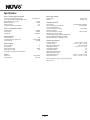
Specifications
Zones 1-6 Power Amplifier Outputs
Continuous Average Output Power
Two channels driven 30-20kHz @1% THD
Rated Distortion (1/2 power)
Rated Impedance
Damping Factor
Frequency Response (20-20kHz)
Zones 1-6 Preamplifier Outputs
Variable output
Fixed output
Impedance
Source Inputs 1-6
input Impedance
Input Sensitivity for rated power
Input Overload
Emitter Outputs
Source Outputs
Sum Outputs
Output Drive Current
Output Drive Voltage
Compatible with single and dual emitters
System
System On
External Mute
Zone Trigger Outputs
Output Power
Outputs
40W (20W x 2)
0.40%
6 Ohms
50+
±2 dB
Power Requirements
Power Supply
Power Consumption all channels
driven to full-rated power
Cower Consumption average
operating conditions
Power Consumption no signal
USA Safety Listing (UL 6500)
Canada Safety Listing (CAN/CSA E60065.00)
CE Listing/SEMKO (EN60065, EN55013,
EN55020, EN6100-3-2, EN6100-3-3/A1)
0-600mV
600mV
600 Ohms
10K
300mV RMS
3V RMS
Physical Specifications
Unit Size Millimeters
Unit Size Inches
Shipping Size Millimeters
Shipping Size Inches
Unit Weight Kilograms
Unit Weight Pounds
Shipping Weight Kilograms
Shipping Weight Pounds
Keypad Size Millimeters
Keypad Size Inches
6
2
100mA
12V
12V @ 50mA
3-12V DC
NuVo reserves the right to change specifications
without notice.
21
12V @ 50mA
6 (zones 1-6)
120VAC/240VAC 50/60Hz
340VA (290W)
50VA (40W)
30VA (12.5W)
88 H x 430 W x 325 D
3 1/2 H x 17 W x 12 3/4 D
290 x 540 x 440
11 3/8 x 21 1/4 x 17 3/8
7.8
17.0
12.7
28.0
107.2 H x 41.5 W x 32.5 D
4 1/4 H x 1 5/8 W x 1 1/4 D
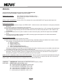
Addendum
Control Interface Description Document for the Nuvo E6D Main Unit
Revision E (for Nuvo E6D Mark II systems only) June 8, 2006
DB9M PORT PINOUTS:
Nuvo Transmit to System Controller on pin 2.
Nuvo Receive from System Controller on pin 3.
Ground on pin 5.
SERIAL PORT PARAMETERS: RS232, RTS/CTS or software flow control (XON/XOFF) NOT required, 9600 baud, 8N1
protocol.
RULES OF PROTOCOL:
(1) For alpha ASCII characters, always use UPPER CASE. In this document, actual characters in a string are presented in
BOLD type.
(2) All numerical fields are coded as ASCII digit characters.
(3) Each Command string is STARTED with an ASCII “*” character and terminated by a <CR> character (0D hexadecimal).
Each response string issued by the E6D will START with an ASCII “#” and be terminated with a <CR> character (0D
hexadecimal).
(4) If a command has an error in it (does not adhere to exact command syntax), the E6D will respond with a “#?<CR>”
string.
(5) Whenever queuing multiple commands to the E6D, the host program should pause for 50 milliseconds between
commands to prevent buffer overruns.
NUVO POWER-ON STATE:
(1) Each zone is OFF until ON command is received.
(2) Each zone's ZoneSet status will be as set by the special key combination settings as detailed in the owner's manual.
If no keypad is connected with a given zone address, then ZoneSet will default to:
A. OR0 (No override)
B. BASS+0 (Bass FLAT)
C. TREB+0 (Treble FLAT)
D. GRP0 (SOURCE GROUPING OFF)
E. VRST1 (VOLUME RESET TO 50 dB ON)
If these zone settings are overridden by the commands which follow in this document, the overridden values will reset
to the default values above upon cycling power on the Main Unit.
(3) For the first four seconds after power-on, a series of non-control related characters will be issued at a wide range of
baud rates. These are necessary queries to a program that may be running on a connected PC for the purpose of
Firmware field upgrades. They should be ignored by the host control system.
NON-VOLATILE COMMANDS AND ASSOCIATED RESPONSES With the exception of commands associated with setting the
IR carrier frequency, the effect of all commands is non-permanent; i.e. when power is cycled on the main unit, it will return to
default values. The commands that are an exception to this rule follow in this section.
*********************************************************************************
*IRSETSR<CR> Reads status of SOURCE IR carrier frequency settings.
COMMAND:
RESPONSE: #IRSET:aa,bb,cc,dd,ee,ff<CR> where:
aa = IR carrier frequency of SOURCE 1 ("38" or "56")
bb = carrier frequency of SOURCE 2 ("38" or "56")
cc = carrier frequency of SOURCE 3 ("38" or "56")
dd = carrier frequency of SOURCE 4 ("38" or "56")
ee = carrier frequency of SOURCE 5 ("38" or "56")
ff = carrier frequency of SOURCE 6 ("38" or "56")
22
NOTE: the Main Unit ships with the carrier frequency DEFAULT setting of 38 KHz for all six sources.
*********************************************************************************
COMMAND: *IRSETDF<CR> Restores DEFAULT SOURCE IR carrier frequency settings (38 KHz for all six sources).
RESPONSE: Same response as for #IRSETSR<CR>
*********************************************************************************
COMMAND: *SxIR56SET<CR> - sets SOURCE x to 56 KHz IR repeat carrier (x is 1 to 6).
RESPONSE: Same response as for #IRSETSR<CR>
*********************************************************************************
COMMAND: *SxIR38SET<CR> - sets SOURCE x to 38 KHz IR repeat carrier (x is 1 to 6).
RESPONSE: Same response as for #IRSETSR<CR>
*********************************************************************************
COMMAND/RESPONSE DESCRIPTIONS.
NOTE zone number field xx should ALWAYS include a lead zero (“0”) for zone numbers less than 10.
COMMAND: *ZxxCONSR<CR> - Connect STATUS REQUEST where xx is zone # from 1 to
12.
RESPONSE: #ZxxPWRppp,SRCs,GRPt,VOL-yy,Pzzz<CR> -ppp = “ON” (2 characters)
or “OFF” (3 characters)
The remaining fields are not included in the response if ppp is “OFF”:
-s = SOURCE NUMBER 1 to 6
-q = 0 if SOURCE GROUP is ON 1if SOURCE GROUP is OFF
-yy = level below max in dB: -00 to -78 dB (include lead 0 for all single-digit
values)
-yy = “MT” if in MUTE state
-yy = “XM” if external MUTE is being held
active
-zzz = “MST” if this zone is PARTY MASTER
-zzz = “SLV” if this zone is SLAVED to a
PARTY MASTER in another zone
-zzz = “OFF” if this zone is under LOCAL CONTROL only (either there is no
party master, or this zone has been manually
overridden)
This response will also be issued in response to pressing the ON/OFF, VOLUME, or SOURCE
keys on a KEYPAD. NOTE the response will be issued if a SOURCE key is pressed on a
zone that is powered OFF even though the key press has no effect on the system. It will be
output at every increment during a volume ramp initiated by HOLDING a VOLUME UP or
VOLUME DOWN key on a keypad. It will also be issued at every increment of a volume
ramp commanded by the *ZxxVOL+<CR> and *ZxxVOL-<CR> commands (see below).
The MUTE value will be asserted if a *ZxMTON<CR> command has been received, OR if the
volume is run all the way to the lowest possible point (volume off). An active EXTERNAL
23
MUTE input, however, will always override other volume response values with the “XM” response.
*********************************************************************************
COMMAND:
*ZxxSETSR<CR> ZoneSet STATUS REQUEST where xx is zone # from 1 to 12.
RESPONSE: #ZxxORp,BASSyy,TREByy,GRPq,VRSTu
-p = 1 if at least one of the permanent
values have been overridden* by an RS232 command.
-yy = EQ level, dB, 12 to +0 (flat) to
+12 in 2 dB increments if
set by RS232, -8, -6,-4, 0,
+4, +6, +8 if set on keypad.
-q = 0 if SOURCE GROUP is ON
1 if SOURCE GROUP is OFF
-u = 0 if VOLUME RESET is ON
1 if VOLUME RESET is OFF
*override set to 1 FOR THIS ZONE only if one of commands *ZxxBASSyy<CR>, *ZxxTREByy<CR>, or
*ZxxGRPq<CR> are issued (see descriptions below).
Once a parameter has been SET by one of these commands, it will remain UNTIL:
a. power is cycled on the Main Unit either with the front panel power switch or by removing AC power. Upon power-up,
the system will restore keypad permanent
settings (see the User Manual for details on how to perform these settings).
b. an operator manually sets one of these parameters from a keypad. This takes the unit out of OVERRIDE state, but
other RS232-commanded settings will remain until another RS232 command overrides them, or power is cycled.
This response is also issued whenever these parameters are set from a keypad.
*********************************************************************************
COMMAND:
*ZxxON<CR> Turn zone xx ON.
RESPONSE: Same response as for *ZxxCONSR<CR>
*********************************************************************************
COMMAND:
*ZxxOFF<CR> Turn zone xx OFF.
RESPONSE: Same response as for *ZxxCONSR<CR>
*********************************************************************************
COMMAND:
*ALLOFF<CR> Turn ALL zones OFF.
RESPONSE: #ALLOFF<CR>
This RESPONSE is also issued when ALL OFF is pressed on any KEYPAD.
*********************************************************************************
COMMAND:
*ALLV+<CR> Ramp ALL zones UP at a 10 dB/second rate in 1 dB steps.
RESPONSE: #ALLV+<CR>
The ramp action will be cancelled when all zones reach MAXIMUM volume, or when an *ALLHLD<CR> Command is received.
Note that to stop the ramp with this command before maximum volume, one reference zone must be periodically polled with a
*ZxxCONSR<CR>
24
Command to determine when the desired volume point has been reached. Note that ramps in different zones may start at
different levels and will all ramp at the same rate.
*********************************************************************************
COMMAND:
*ALLV-<CR> Ramp ALL zones DOWN at a 10 dB/second rate in 1 dB steps.
RESPONSE: #ALLV-<CR>
The ramp action will be cancelled when all zones reach MINIMUM (OFF) volume, or when an *ALLHLD<CR> Command is
received. Note that to stop the ramp with this command before the minimum volume, one reference zone must be periodically
polled with a *ZxxCONSR<CR> Command to determine when the desired volume point has been reached. Note that ramps in
different zones may start at different levels and will all ramp at the same rate.
*********************************************************************************
COMMAND:
*ALLHLD<CR> Stops ramp action initiated by *ALLV+<CR> Or *ALLV-<CR>
RESPONSE: #ALLHLD-<CR>
This results in a HOLD of the level at time of command receipt.
*********************************************************************************
COMMAND:
*ALLMON<CR> ALL MUTE ON.
RESPONSE: # ALLMON<CR>
*********************************************************************************
COMMAND:
*ALLMOFF<CR> ALL MUTE OFF.
RESPONSE: #ALLMOFF<CR>
********************************************************************************
COMMAND:
*ZxxSRCp<CR> Switch zone xx to SOURCE p ( 1 to 6).
RESPONSE: Same response as for *ZxxCONSR<CR>
*********************************************************************************
COMMAND:
*ZxxVOLyy<CR> Set volume of zone xx to level yy below max in dB from 0 to 78 dB (include lead 0 for all
single-digit values).
RESPONSE: Same response as for *ZxxCONSR<CR>
*********************************************************************************
COMMAND:
*ZxxVOL+<CR> STARTS zone xx volume ramp UP at the rate of +10 dB per second in +1 dB steps. (This is
the same as holding VOLUME UP key on a KEYPAD for 1 second).
RESPONSE: Same response as for *ZxxCONSR<CR>, updated 10 times per second.
*********************************************************************************
COMMAND:
*ZxxVOL-<CR> STARTS zone xx volume ramp DOWN at the rate of -10 dB per second in -1 dB steps. (This
is the same as holding VOLUME UP key on a KEYPAD for 1 second).
RESPONSE: Same response as for *ZxxCONSR<CR>, updated 10 times per second.
*********************************************************************************
COMMAND:
*ZxxVHLD<CR> STOPS zone xx volume ramp initiated by *ZxxVOL++<CR> or *ZxxVOL--<CR> commands.
This results in a HOLD of the level at time of command receipt.
RESPONSE: #ZxxVHLD<CR>
*********************************************************************************
COMMAND:
*ZxxMTON<CR> zone xx MUTE ON (mutes currently connected source)
RESPONSE: Same response as for *ZxxCONSR<CR>
25
*********************************************************************************
COMMAND:
*ZxxMTOFF<CR> zone xx MUTE OFF (returns zone output to currently connected source at previous volume
setting).
RESPONSE: Same response as for *ZxxCONSR<CR>
*********************************************************************************
COMMAND:
*ZxxBASSyyy<CR> zone xx BASS EQ with yyy = EQ level, dB, 12 to +0 (flat) to +12 in 2 dB increments.
USE LEAD “0” IN TENS PLACE FOR VALUE LESS THAN 10.
RESPONSE: Same response as for *ZxxSETSR<CR>
NOTE: sending this command to the E6D will override the non-volatile BASS setting (set from keypad) for this zone until power
is cycled.
*********************************************************************************
COMMAND:
*ZxxTREByyy<CR> zone xx TREBLE EQ with yyy = EQ level, dB, 12 to +0 (flat) to +12 in 2 dB increments.
USE LEAD “0” IN TENS PLACE FOR VALUE LESS THAN 10.
RESPONSE: Same response as for *ZxxSETSR<CR>
NOTE: sending this command to the E6D will override the non-volatile TREBLE setting (set from keypad) for this zone until
power is cycled.
*********************************************************************************
COMMAND:
*ZxxGRPON<CR> zone xx SOURCE GROUP ON.
RESPONSE: Same response as for *ZxxSETSR<CR>
NOTE: sending this command to the E6D will override the non-volatile GROUP setting (set from keypad) for this zone until
power is cycled.
*********************************************************************************
COMMAND:
*ZxxGRPOFF<CR> zone xx SOURCE GROUP OFF.
RESPONSE: Same response as for *ZxxSETSR<CR>
NOTE: sending this command to the will override the non-volatile GROUP setting (set from keypad) for this zone until power is
cycled.
*********************************************************************************
COMMAND:
*ZxxVRSTON<CR> zone xx VOLUME RESET ON.
RESPONSE: Same response as for *ZxxSETSR<CR>
NOTE: sending this command to the E6D will set override (lock out KEYPAD non-address DIP
switches) for this zone until power is cycled.
*********************************************************************************
COMMAND:
*ZxxVRSTOFF<CR> zone xx VOLUME RESET OFF.
RESPONSE: Same response as for *ZxxSETSR<CR>
NOTE: sending this command to the E6D will set override (lock out KEYPAD non-address DIP
switches) for this zone until power is cycled.
*********************************************************************************
COMMAND:
*ZxxLKON<CR> zone xx KEYPAD LOCK ON This will INHIBIT ANY keypad control input on the zone. This is
the same as activating the Parental lock control at a keypad by holding down a SOURCE key for three
seconds).
RESPONSE: #ZxxLKON<CR>6
26
*********************************************************************************
COMMAND:
RESPONSE:
*ZxxLKOFF<CR> zone xx KEYPAD LOCK ON This will RESTORE ALL keypad control input on the zone
(useful as Parental lock control) . This is the same as deactivating the Parental lock control at a keypad by
holding down a SOURCE key for three seconds).
#ZxxLKOFF<CR>
*********************************************************************************
COMMAND:
*VER<CR> Firmware version query.
RESPONSE:
#NUVO_E6D_vx.yy<CR> where x is the major version number and yy is the minor version number.
*********************************************************************************
RESPONSE: #EXTMON<CR> Issued whenever the External MUTE first activates (closure to ground) and 0 whenever the
External MUTE de-activates (open connection to ground).
NOTE: there is no COMMAND associated with this response; it is always initiated by a change at the EXT. MUTE input.
*********************************************************************************
RESPONSE: #EXTMOFF<CR> Issued whenever External MUTE de-activates (open connection to ground).
NOTE: there is no COMMAND associated with this response; it is always initiated by a change at the EXT. MUTE input.
27
ESS513 0706