1
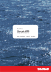
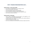
N A I S 3 0 0 MANUAL NAVICO NAIS-300 Class B Transceiver English © 2007 Navico AS The technical data, information and illustrations contained in this publication were to the best of our knowledge correct at the time of going to print. We reserve the right to change specifications, equipment, installation and maintenance instructions without notice as part of our policy of continuous development and improvement. No part of this publication may be reproduced, stored in a retrieval system or transmitted in any form, electronic or otherwise, without prior permission from Navico AS. No liability can be accepted for any inaccuracies or omissions in the publication, although every care has been taken to make it as complete and accurate as possible. Contents Iss.1.0 DEC 07 WP Contents 1 Introduction 5 1.1 General overview 5 1.2 SimNet/NMEA2000 6 2 Installation 7 2.1 General 7 2.2 Mounting 7 2.3 Cabling 8 2.4 SimNet/NMEA2000 cable 9 SimNet (300-N model only) NMEA2000 (300-L model only) 9 10 2.5 NMEA0183-HS (RS232) 10 2.6 NMEA0183-HS (RS485) 10 2.7 Transmit disable switch 10 2.8 GPS antenna 10 2.9 VHF antenna 11 3 Configuration 15 3.1 General 15 3.2 Connecting to a computer 15 4 Operation 17 4.1 General 17 4.2 Indicators 17 PWR 17 BIIT (Built In Integrity Test) 17 TX 18 Contents RX 4.3 Enable/disable switch (Silent Mode) 5 Appendix 18 18 19 5.1 Maintenance 19 5.2 Troubleshooting 19 5.3 Accessories 19 5.4 Product specifications 20 5.5 Dimensions22 5.6 Service and warranty22 5.7 Declaration of Conformity (EU)23 Contents 1 Introduction 1.1 General overview The NAIS-300 is a Class B Transponder that’s purpose is to transmit the position and other information about your vessel, to other AIS equipped vessels. It is housed in a rugged waterproof enclosure to withstand the rigors of the marine environment. The NAIS-300 uses a sophisticated automatic digital time sharing technology which enables the exchange of static information like; MMSI (Maritime Mobile Service Identifier) Number, Vessel’s Name, Call Sign and Type. Also dynamic data like; Position, Course, Distance and more, from ship to ship, and from ship to shore based traffic stations. When connected to a compatible chart plotter, it will provide a representation of the position and movements of all AIS equipped vessels within VHF range The advantages of the NAIS-300 are: • Increased awareness of the current shipping situation within your VHF range through the exchange of data between vessels. • Improving traffic management in busy shipping lanes through exchanging information between vessels and shore based traffic stations. • Reporting information automatically in shipping areas where it is mandatory. As with all electronic navigational equipment, it is only an aid to navigation and should not be used as a substitute for good seamanship. Remember - Maritime law requires that you keep a good lookout at all times. Introduction 1.2 SimNet/NMEA2000 SimNet is Navico’s proprietary high speed data bus network compatible with NMEA2000. It provides intelligent sharing of data and control information between a wide range of marine electronics and instruments. Introduction 2 Installation 2.1 General The NAIS-300 is designed to be mounted on a flat surface somewhere out of sight, but easily accessible. However, to determine the best possible location, you need to consider how and where, you are going to run the cabling from the sides of the unit. The NAIS-300 is very simple to install, however, the performance of the equipment is directly affected by the quality of the installation. Please read these instructions carefully before attempting installation. If in any doubt, consult a qualified marine electronics engineer. 2.2 Mounting The transceiver requires a flat surface with a minimum area of at least 210mm x 130mm (8.3in x 5.1in) for mounting, with an overall area of 210mm x 250mm (8.6in x 9.8in) to allow for cables. The surface should be rigid and sturdy enough to be able to support the weight of the unit, taking into account the shock loads likely to be encountered when the vessel is under way in heavy seas. 1 2 3 Hold the unit against the surface where it is to be mounted, and mark the position of the four holes with a pencil. Drill a 3.7mm (.145in) hole on each corner mark. Align the holes on the NAIS-300 with those you have just drilled, and fasten with the 4 - No.8 x 3/4 self tapping screws supplied. Installation 2.3 Cabling Once you have secured your NAIS-300 to a flat surface, you will need to connect the power, SimNet/NMEA2000 and RS232 cables supplied with the unit. The RS485 cable and switch are not supplied, but would be fitted in the same manner. Power +12vdc Out +ve NMEA0183-HS (RS485) 0v. Out -ve In +ve In -ve NMEA0183-HS (RS232) Out -ve Gnd. In +ve External Switch Switch + Switch - Figure 2.1 - Connector wiring With reference to the connector wiring, Figure 2.1 and the assembly diagram, Figure. 2.2, wire your unit as follows: Retaining Screws Clamp SimNet/NMEA2000 Socket Splash Cover Nipples Power Connector Grommet SimNet/NMEA2000 Connector NMEA0183-2 & Switch Connector NAIS-300 Case Figure 2.2 - NAIS-300 assembly Installation 1 2 3 4 5 6 7 Choose the nipples directly above the parts of the connector you want to wire into and cut off the top section to the required diameter. Pass the power and RS232 cables through the cradle and then through the hole in the respective nipple. Bare the ends of the cables and wire into the correct section of the connector. Once you have wired the two connectors, firmly push them into their mating part in the main unit. Slide the grommet down the cable until it is seated on the main housing. Make sure that there is a little excess cable beneath it, ensuring that the cable is not pulled tight. Place the clamp over the grommet and screw down with the two screws supplied. Make a small loop from the cables and cable tie them down to the tongue of the clamp. Figure 2.3 - NAIS-300 showing finished wiring assembly 2.4 SimNet/NMEA2000 cable (supplied) The NAIS-300 is connected to the SimNet/NMEA2000 databus using the cable supplied. Pull the splash cover off of the SimNet/NMEA2000 socket, ensure the connector on the end of the cable is in the correct orientation and press firmly into the socket. SimNet (300-N model only) With the supplied cable connected to the NAIS-300, connect the other end into the vessels SimNet network. Installation NMEA2000 (300-L model only) With the supplied cable connected to the NAIS-300, connect the other end into the supplied T-connector, then connect this into the vessels NMEA2000 network. 2.5 NMEA0183-HS (RS232 supplied) This data cable is used to connect the NAIS-300 to a PC or laptop in order to configure it, and for AIS enabled PC chartplotter applications. For further information regarding the wiring of this cable please refer to chapter 3.2 2.6 NMEA0183-HS (RS485 not supplied) This data cable is used for connectivity to AIS enabled chart plotters and other marine equipment with an NMEA0183-HS interface. For wiring information, refer to Figure 2.1. (NMEA0183-HS is specified at 38.4kbaud and is not compatible with conventional NMEA0183, which operates at the lower speed of 4800baud) 2.7 Transmit disable switch (not supplied) Any momentary action, push to make switch can be used. Take a wire from each terminal of the switch and wire them into the connector. Refer to figure 2.1. Because there is negligible current drawn through this cable, any suitable two core cable will do, providing it forms a good seal once inserted in the grommet. Refer to section 4.3. 2.8 GPS antenna The antenna, ideally needs to be mounted as low as possible with a clear view of the sky to minimise errors due to movement over and above the transitory movement of the vessel. The GPS antenna is capable of being flush mounted on a suitable flat area of the cabin roof or deck area. In this configuration, fit the supplied rubber gasket under the antenna and use the four threaded studs, nuts and washers to fix the antenna down. 10 Installation The cable can be routed in the molding to drop down directly underneath, or by breaking out the thin traps, the cable can be routed out of the side of the antenna. Rx Alternatively, the antenna may be fixed on a standard 1” threaded mounting pole (Not supplied). Attach the supplied mounting base to the antenna with the four screws, thread the cable down the center hole and through the pole. Thread the pole into the mounting base, before attaching the pole to the superstructure. Tx BIIT To minimize interference, place the antenna in a position away from steel constructions, wires, metal masts, sources of electrical interference, such as radar etc. If installing the GPS antenna close to other antennas, mount it either above or below their radiation beams. PWR NAIS-300 The antenna cable is terminated in a screw fit connector (SMA). Push the antenna plug into the socket on the side of the unit and screw down the retaining collar. 73.5mm 2.9in GPS Antenna VHF Antenna Figure. 2.3 - Antenna connections 210mm (8.27in) 2.9 VHF antenna (not supplied) North American Users - To meet FCC (Federal Communications Commission) rules on Radio Frequency Exposure, it is recommended that the VHF antenna is mounted at least 3m (10ft) away from any area accessible to any personnel on board. If this distance is achieved by vertical separation, the antenna must be at least 5m (16.5ft) above deck. This guideline applies only to antennas not exceeding 3dBi gain. Failure to observe these recommendations may expose those within the MPE (Maximum Permitted Exposure) radius of 1m (3ft) to RF absorption levels that exceed the FCC safe limits. Installation 11 The most important factor in the performance of any AIS transceiver will be the quality and positioning of the antenna. As the range of VHF signals are governed by line of sight, the antenna should be placed as high as possible, while remaining clear of any metallic objects. Long whip antennas are generally recommended for larger boats, although the most popular antennas for marine use is 1m (3ft 3in) long. On sailboats these are usually mounted on the masthead, where the length of the antenna keeps it clear from the navigation lights and wind vanes. This type of antenna can also be mounted on the cockpit roof or powerboat garages. For maximum range, it is recommended that a VHF antenna specifically tuned for use with an AIS is used, and mounted away from the standard VHF antenna. Vertical separation is preferred, but where this is not practical, at least 5 metre horizontal spacing is recommended The antenna coaxial cable and any connectors used must be rated at 50Ω. Under no circumstances should standard domestic TV cable and connectors be used. Incorrectly rated cabling and connectors could result in power not reaching the antenna, but also power could be reflected back into the NAIS300 unit, reducing its performance. The quality of any connections and integrity of the cable will directly affect the performance of the radio. Poor soldering or corrosion of the terminals can impair performance. We recommend that screw or crimp terminal type connectors are not used for any through deck fittings - a good quality waterproof solder terminal connector will be less susceptible to poor connection due to corrosion of the contacts. To ensure the best performance of the radio, the antenna cable should be routed where it is least likely to interfere with, or receive interference from other electronic equipment, such as echo sounder transducer cables and high current carrying cables. 12 Installation The antenna cable should terminate in a standard marine PL259 plug fitting. Connect the antenna plug to the socket on the side of the unit and screw the retaining collar down. Figure 2.3. To avoid possible water damage to the transceiver, it is recommended that all cables are looped to provide a drip path. Installation 13 14 Installation 3 Configuration 3.1 General Before the NAIS-300 can become fully functional, it will be necessary to load the following information about your vessel into the unit: • • • • • Vessels Name Call Sign MMSI Number Vessels Dimensions Vessel Type In order to enter this information, you will need to connect your NAIS-300 to your PC or laptop through the supplied RS232 cable. This can be done in the comfort of your living room at home. 3.2 Connecting to a computer Wire one end of the supplied RS232 cable into the connector block on the main unit, refer to Fig 2.1, then plug the 9 pin RS232 connector into the serial port on your PC or laptop. If your PC or laptop does not have a serial port, and you are using a USB to serial converter, please ensure this is fully installed before proceeding. 1 2 3 4 5 Insert the Installation CD into your computer and locate the “Setup.exe” file. Double click the “Setup.exe” file to begin installation. Follow the on screen prompts to install the .Net framework, if required. When a security warning is displayed, Press “Install”. A Start Menu folder and shortcut will be created with the name “proAIS“. This shortcut should be used to re-launch the application as required. Configuration 15 For security reasons the MMSI of the vessel cannot be changed once programmed. Do not programme the MMSI unless you are certain you have the correct information. Please check the number entered carefully. If the MMSI programmed is incorrect the AIS transponder will need to be returned to the supplier for factory reset. Should it become necessary to change your MMSI, for example, if you wish to re-install your NAIS-300 into a new vessel; you will need to contact your local Navico dealer about reprogramming a new number. If no MMSI is entered the AIS transponder will operate in receive only mode. The vessels own position will not be transmitted. An MMSI must be entered to allow the AIS transponder to transmit its own position to other vessels. For a more detailed description of how to configure your NAIS-300, please refer to the application user guide on the CD supplied with the unit. 16 Configuration 4 Operation 4.1 General The NAIS-300 has a limited user interface, consisting of a transmit enable/disable switch, (not supplied), and four indicators on the top of the unit, they are: • • • • PWR [Green] - Power/GPS Lock Status/Silent Mode BIIT [Red] - Built In Integrity Test TX [Yellow] - Transmit RX [Blue] -AIS Message Received 4.2 Indicators At power up, all four LED’s will light continuously for five seconds to show that they are working, then they will go into the following routines: PWR After the initial five seconds the LED will do two short flashes and a longer pause before repeating itself. This will continue until a GPS position fix is acquired. Once a fix has been obtained, the LED will stay on continuously. If, after a GPS fix, the transmitter has been disabled, (Silent Mode), the LED will flash at a rate of one second on and one second off. BIIT (Built In Integrity Test) The NAIS-300 is constantly monitoring and testing the integrity of the AIS transceiver. After the initial five seconds the LED will go out. Should a fault be detected within the unit, the “BIIT” LED will start to flash. The flash sequences listed below indicate the specific faults: 1 2 3 4 5 flash - transponder not reponding flashes - transmitter fault flashes - receiver fault flashes - VHF antenna VSWR fault flashes - no GPS sensor Operation 17 6 flashes - noise threshold exceeded 7 flashes - voltage supply fault The “BIIT” message will remain there until the fault is cleared by the NAIS-300 circuitry, or the unit has been repaired. TX After the initial five seconds the LED will then go out. It will light for one second every time the unit transmits its AIS data. The LED will also light continuously if a transmitter time-out fault occurs. RX After the initial five seconds the LED will flash every time an AIS message is received. 4.3 Enable/disable switch (Silent Mode) This switch allows you to turn the NAIS-300’s VHF transmitter “on” or “off”, rendering you either visible or invisible to other AIS equipped vessels in your VHF range. The default mode is with the transmitter active, “on“. To turn your transmitter off push the switch once. The “PWR” LED on the top of the unit will start to flash at a rate of one second on and one second off. The “TX” LED will remain off. To turn your transmitter back on simply push the switch again. This mode will be stored in the NAIS memory, therefore whatever mode you are in when power is turned off, will be the same when power is restored. 18 Operation 5 Appendix 5.1 Maintenance Periodically check that the cables are secure and that the connectors have not worked their way loose. 5.2 Troubleshooting These simple checks should be carried out before seeking technical assistance and may save time and expense. General Symptom Unit will not switch on Possible Cause Remedy • Faulty connector to power • Fuse has blown No GPS Position fix • Antenna or cable problem • No AIS transmission • MMSI not entered • • Transmit disabled No reception of NMEA0183-HS • RS232 cable problem RS485 cable problem • No reception of SimNet/NMEA2000 data • SimNet/NMEA cable problem • • Check power connection • Replace fuse and check power supply • Check antenna cable and connections Enter MMSI number (see chapter 3) • Enable Transmit (see section 4.3) Check cables Check SimNet/NMEA cables • Check power cables 5.3 Accessories The following accessories are available from local Navico agents: VA14* VHF AIS antenna - S/S whip with 20 metres Cable, terminated in a PL259 plug. * One off required for operation Appendix 19 5.4 Product specifications AIS Type Class B for use on non-SOLAS craft VHF Receiver Receiver type Dual TDMA (shared DSC) Sensitivity < -107dBm for 20% PER Transmit power2Watt Type ApprovalMeets IEC62287-1 GPS Receiver Receiver type Integral 16 channel receiver EMC IEC60945 Power Voltage 10.8 – 15.6VDC Current <0.5A SimNet/NMEA2000 Network load 1 Connectors VHF Antenna PL259 GPS Antenna SMA Compass mounting Safe distance 0.3m Environmental Waterproofing IP67 Temperature range Operational -15°C to +55°C Storage -40°C to +85°C Physical Size210mm x 130mm x 73.5mm Weight 650g Interfaces NMEA0183-HS Out38kbaud VDM, VDO, RMC, ALR In38kbaud for configuration & testing only SimNet/NMEA2000 PGN’s NMEA2000 Mandatory PGNs 59392 ISO Acknowledgment 59904 ISO Request 60928 ISO Address Claim 126996 NMEA2000 Product Information NMEA2000 Data PGNs 126992 System Time 129025 Position, “Rapid Update” 129026 COG & SOG, “Rapid Update” 20 Appendix NMEA2000 AIS PGNs 129038 Class A Position Report 129039 AClass B Position Report 129040 Class B Extended Position Report 129792 DGNSS Broadcast Binary Message 129793 UTC and Date Report 129794 Class A Static and Voyage Related Data 129795 Addressed Binary Message 129796 Acknowledge 129797 Binary Broadcast Message 129798 SAR Aircraft Position Report 129800 UTC/Date Enquiry 129801 Addressed Safety Message 129802 Broadcast Safety Message 129803 Interrogation 129804 Assignment Mode Command 129805 Data Link Management Message Appendix 21 5.5 Dimensions Rx Tx BIIT 73.5mm 2.9in PWR NAIS-300 210mm (8.27in) 167.5mm (6.6in) Figure 5.1 - NAIS-300 dimensions Figure 5.2 - GPS Antenna dimensions 5.6 Service and warranty If it is necessary to have a unit repaired, please contact your local authorized dealer. For worldwide warranty details and a list of authorised Navico agents please refer to the Warranty Card supplied with this unit. 22 Appendix 5.7 Declaration of Conformity (EU) English Hereby, Navico AS declares that this NAIS-300 is in compliance with the essential requirements and other relevant provisions of Directive 1999/5/EC. Finnish Navico AS vakuuttaa täten että NAIS-300 tyyppinen laite on direktiivin 1999/5/EY oleellisten vaatimusten ja sitä koskevien direktiivin muiden ehtojen mukainen. Dutch Hierbij verklaart Navico AS dat het toestel NAIS-300 in overeenstemming is met de essentiële eisen en de andere relevante bepalingen van richtlijn 1999/5/ EG. French Par la présente, Navico AS déclare que ce NAIS-300 est conforme aux exigences essentielles et aux autres dispositions de la directive 1999/5/CE qui lui sont applicables. Swedish Härmed intygar Navico AS att denna NAIS-300 står i överensstämmelse med de väsentliga egenskapskrav och övriga relevanta bestämmelser som framgår av direktiv 1999/5/EG. Danish Undertegnede Navico AS erklærer herved, at følgende udstyr NAIS-300 overholder de væsentlige krav og øvrige relevante krav i direktiv 1999/5/EF. German Hiermit erklärt Navico AS, dass sich dieses NAIS-300 in Übereinstimmung mit den grundlegenden Anforderungen und den anderen relevanten Vorschriften der Richtlinie 1999/5/EG befindet. (BMWi) Greek µε την παρουσα Navico AS δηλωνει οτι NAIS-300 συµµορφωνεται προς τις ουσιωδεις απαιτησεις και τις λοιπες σχετικες διαταξεις της οδηγιας 1999/5/εκ. Italian Con la presente Navico AS dichiara che questo NAIS-300 è conforme ai requisiti essenziali ed alle altre disposizioni pertinenti stabilite dalla direttiva 1999/5/CE. Spanish Por medio de la presente Navico AS declara que el NAIS-300 cumple con los requisitos esenciales y cualesquiera otras disposiciones aplicables o exigibles de la Directiva 1999/5/CE. Portuguese Navico AS declara que este NAIS-300 está conforme com os requisitos essenciais e outras provisões da Directiva 1999/5/CE. The equipment named in this declaration, is intended for use in international waters as well as coastal sea areas, and inland waterways administered by countries of the E.U. and E.E.A. Website – www.Navico.com Appendix 23 www.navico.com