1
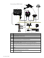
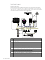
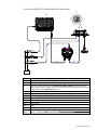
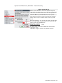
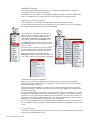
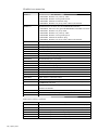
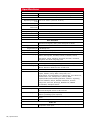
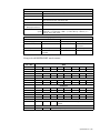
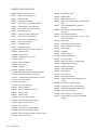
Installation Manual Simrad NSO Multi-Function Display English www.simrad-yachting.com A brand by Navico - Leader in Marine Electronics Blank page Preface Disclaimer As Navico is continuously improving this product, we retain the right to make changes to the product at any time which may not be reflected in this version of the manual. Please contact your nearest distributor if you require any further assistance. It is the owner’s sole responsibility to install and use the instrument and transducers in a manner that will not cause accidents, personal injury or property damage. The user of this product is solely responsible for observing safe boating practices. NAVICO HOLDING AS AND ITS SUBSIDIARIES, BRANCHES AND AFFILIATES DISCLAIM ALL LIABILITY FOR ANY USE OF THIS PRODUCT IN A WAY THAT MAY CAUSE ACCIDENTS, DAMAGE OR THAT MAY VIOLATE THE LAW. Governing Language: This statement, any instruction manuals, user guides and other information relating to the product (Documentation) may be translated to, or has been translated from, another language (Translation). In the event of any conflict between any Translation of the Documentation, the English language version of the Documentation will be the official version of the Documentation. This manual represents the product as at the time of printing. Navico Holding AS and its subsidiaries, branches and affiliates reserve the right to make changes to specifications without notice. Copyright Copyright © 2011 Navico Holding AS. Warranty The warranty card is supplied as a separate document. In case of any queries, refer to the brand web site of your display or system. www.simrad-yachting.com Preface | 1 Compliance Statements The Simrad NSO complies with the following regulations: • FCC Part 15 • CE compliant per EN60945 • C - Tick For more information please refer to our website: www.simrad-yachting.com. Warning The user is cautioned that any changes or modifications not expressly approved by the party responsible for compliance could void the user’s authority to operate the equipment. This equipment has been tested and found to comply with the limits for a Class B digital device, pursuant to Part 15 of the FCC rules. These limits are designed to provide reasonable protection against harmful interference in a residential installation. This equipment generates, uses and can radiate radio frequency energy and, if not installed and used in accordance with the instructions, may cause harmful interference to radio communications. However, there is no guarantee that the interference will not occur in a particular installation. If this equipment does cause harmful interference to radio or television reception, which can be determined by turning the equipment off and on, the user is encouraged to try to correct the interference by one or more of the following measures: 2 | Preface • Reorient or relocate the receiving antenna • Increase the separation between the equipment and receiver • Connect the equipment into an outlet on a circuit different from that of the receiver • Consult the dealer or an experienced technician for help Contents Preface ...................................................................................................1 Introduction ...........................................................................................7 About this manual .................................................................................. 7 Conventions .......................................................................................... 7 Important safety and warning information................................................. 7 Check the parts..................................................................................... 8 Overview .............................................................................................. 10 Installing the NSO components ........................................................... 12 Mounting location................................................................................. 12 Secure the Marine Processor Unit ........................................................... 12 DI10 / DI15 Display Panel mount ............................................................ 13 DI10 / DI15 Display Bracket Mount ......................................................... 14 OP40 Panel Mount ................................................................................ 15 Card Reader Installation ....................................................................... 16 System architecture ............................................................................. 17 Networking, Data Interfacing ................................................................. 17 SimNet / NMEA 2000 ......................................................................... 17 Ethernet: (NETWORK ports) ................................................................ 17 NMEA0183 ........................................................................................ 17 Data Bridging .................................................................................... 18 Wiring the NSO .....................................................................................24 Power ................................................................................................. 25 Connecting power .............................................................................. 25 Remote Power On .............................................................................. 26 Video Out ........................................................................................... 28 SimNet ............................................................................................... 30 SimNet: The basics ............................................................................ 30 Planning and installing a SimNet backbone ............................................ 31 Power the SimNet network .................................................................. 31 Integrating SimNet and other CAN networks............................................ 35 Ethernet ............................................................................................. 37 Connecting NSO to one other Ethernet performance module ................... 38 Connecting directly to HD Radar ......................................................... 38 Connecting two NSO Processors .......................................................... 38 Connecting to two or more performance modules .................................. 39 NMEA0183 wiring ................................................................................. 40 Preface | 3 External alarm ..................................................................................... 41 Connecting BR24 Radar ....................................................................... 42 Connecting HD Radar ........................................................................... 43 Dual Radar Support .............................................................................. 44 BR24 and HD radar ............................................................................ 44 Connecting BSM-1 Broadband Echosounder ............................................. 45 BSM-1 Transducer adapter cables ........................................................ 46 NSO Auto Pilot Integration .................................................................... 47 Commission the system ........................................................................48 Operating the menu system .................................................................. 48 Turning on for the first time................................................................... 49 Assigning an OP40 control of a single display......................................... 49 Assigning an OP40 to control multiple displays....................................... 49 Unassign a display from an OP40 ......................................................... 50 Configure the next OP40 .................................................................... 50 Finish OP40 configuration ................................................................... 50 OP40 LED sequences.......................................................................... 50 Turning on / off: Normal operation ......................................................... 51 Display control selection: Normal OP40 use ............................................. 51 System settings menu ........................................................................ 52 Language ......................................................................................... 52 Time: Local Time, Time format, Date Format ......................................... 52 Commissioning checklist ....................................................................... 53 Data setup .......................................................................................... 55 SimNet / NMEA2000 setup .................................................................. 55 Source selection (Auto select) ............................................................. 55 Source selection (Manual) .................................................................. 55 SimNet Groups .................................................................................... 57 Damping .......................................................................................... 58 Device List ........................................................................................ 58 Speed Calibration (SimNet Transducers) .................................................. 59 Autopilot Setup .................................................................................... 60 Wiring the autopilot system ................................................................ 60 Verifying the autopilot connection ........................................................ 60 Commissioning the autopilot ............................................................... 60 Dockside setup .................................................................................. 60 Rudder drive setup ............................................................................ 62 Seatrials ........................................................................................... 62 Compass calibration ........................................................................... 63 Setting the transition HI/LO speed ....................................................... 64 Autotuning ........................................................................................ 65 4 | Preface Seastate filter ................................................................................... 65 Setting sailing parameters .................................................................. 65 Manually adjusting steering parameters................................................ 66 Echosounder setup ............................................................................... 69 Depth offset ..................................................................................... 69 Echo sounder software version ............................................................ 69 Water speed calibration (Echosounder transducer) ................................. 69 Water speed averaging (Echosounder transducer) .................................. 69 Temperature calibration (Echosounder transducer) ................................. 69 Transducer type (Echosounder) ........................................................... 70 Radar setup ........................................................................................ 70 Serial port setup .................................................................................. 72 NMEA 0183 output ............................................................................. 72 Fuel and Engines .................................................................................. 73 Vessel Setup ..................................................................................... 73 AIS own vessel .................................................................................... 73 Diagnostics ......................................................................................... 74 NMEA2000 Diagnostics ....................................................................... 74 USER Database UDB .......................................................................... 74 CZone Setup ....................................................................................... 75 Activate Czone Feature....................................................................... 75 Czone Backlight ................................................................................. 75 Check GPS signal ................................................................................. 76 System backup .................................................................................... 76 Restore a backup............................................................................... 76 Backup Waypoints routes and tracks ...................................................... 77 Software upgrades ............................................................................... 78 Displaying current software version ..................................................... 78 NSO or NSE Processor upgrade .......................................................... 79 Screen capture .................................................................................... 81 File transfer ........................................................................................ 81 NSO Drawings ....................................................................................... 82 NSO Dimensions .................................................................................. 82 MO19 Dimensions ................................................................................ 82 DI15 Dimensions .................................................................................. 83 DI10 Dimensions .................................................................................. 83 OP40 Dimensions ................................................................................. 84 NSO Chart Card Reader Dimensions ....................................................... 84 Spare parts ...........................................................................................85 NSO Spare parts .................................................................................. 85 Displays ........................................................................................... 85 Preface | 5 SimNet accessories .......................................................................... 86 Ethernet cables (yellow) ..................................................................... 86 Ethernet cables (RJ45 adapters) .......................................................... 87 Specifications .......................................................................................88 Supported NMEA0183 sentences ............................................................ 89 NMEA 2000 PGN List ............................................................................ 90 NMEA 2000 PGN Receive .................................................................... 90 NMEA2000 PGN Transmit .................................................................... 91 6 | Preface Introduction About this manual This manual is a reference guide for installing the Simrad NSO Multi Function Display. The information in this manual at the time of printing is correct to the best of our knowledge. Navico can not be liable for any inaccuracies or missing information. Due to the constant improvement of Navico’s products. Navico cannot be liable for changes between the product and the manual. Refer to www.simrad-yachting.com for the latest manuals and addendums. Conventions Used when it is necessary to warn personnel that a risk of damage to the equipment or injury/death exists if care is not exercised. Used to draw the reader’s attention to a comment or some important information. Important safety and warning information Please read carefully before use. When navigating the vessel, use the Simrad NSO system only as a navigational aid. Proper navigation of the vessel is the sole responsibility of the vessel operator. The electronic chart used by the NSO System is an aid to navigation only and is designed to supplement, not replace, official government charts. Only official government charts supplemented by notices to mariners contain the information required for safe and prudent navigation. Always supplement the electronic information provided by the Simrad NSO with other plotting sources such as observations, depth soundings, radar and hand compass bearings. Should the information not agree, the discrepancy must be resolved before proceeding any further. Never operate the NSO in Simulate Mode while you are underway. It is the user’s responsibility to ensure that Simulate Mode is used only in safe situations such as when you are moored in a marina. The Global Positioning System (GPS) is operated by the US Government which is solely responsible for its operation, accuracy and maintenance. The GPS system is subject to changes which could affect the accuracy and performance of all GPS equipment anywhere in the world. The accuracy of the Echosounder depth display can be limited by many factors, including the type of transducer, the location of the transducer, and water conditions. Ensure that the transducer is installed correctly and the Echosounder is used correctly. Introduction | 7 Check the parts NSO Processor Packaged parts list NSO Marine Processor OP40 Controller w/4 m (13 ft) Micro-C to SimNet cable Power cable 2m (6.5 ft) Ethernet Adapter cable Utility Cable 12 Pin Connector Caps 2 m (6 ft) NMEA0183, External alarm, Remote Power on Installation Manual Operation manual Quick start guide OP40 Controller Mounting Template NSO Marine Processor Mounting Template Mounting Screws for Marine processor 4 x SCREW, 8Gx1, PAN POZI, S/T,16,LO-HEAD Card reader kit Includes card reader, gasket, bezel, mounting kit. SIMKIT 1: Includes SimNet 5 m (16.5 ft) cable SimNet 7-Prong Multi-Joiner SimNet Termination Plug SimNet 2 m (6 ft) power cable w/terminator 8 | Introduction DI10 and DI15 display parts DI15 Display DI10 Display DI15 Bezel DI10 Bezel DI15 Dust cover DI10 Dust cover DI15 Gasket DI10 Gasket DI15 Cut-out Template DI10 Cut-out Template Common DI10 / DI15 display components Mounting bracket Mounting Bracket knobs Display power cable Cleaning cloth DI Display 5 x SCREW,14G x 1,PAN POZI,S/T,SS 316,BLACK Introduction | 9 Overview 1 12 2 11 3 4 5 7 6 3 Key 10 | Overview 9 10 8 Description 1 Power. For power input 12 or 24 V DC input (see power page 25) 2 Utility. NMEA0183 Port TX (see NMEA0183 Wiring page 40), External Alarm (see External Alarm page 41), Remote Power on 3 AUX. Not used. 4 VIDEO 1. DVI-D Video out. Display 1 video out to connect to a DI10, DI15, MO19 or third party DVI monitor. 5 Power On/Off. Power control button. 6 Power LED. Indicated Power status. 7 HDD LED. Indicates hard drive activity. 8 LINK LED. Indicates if there is a valid Ethernet network connection 9 VIDEO 2. DVI-I Video out. Display 2 video out to connect to a DI10, DI15, MO19 or third party DVI monitor. Duplicates the output of Video 1 port 10 SimNet. Connects the marine processor to a SimNet or NMEA2000 network (see SimNet page 30). 11 Network. Ethernet network port for connecting to other Ethernet network devices. (see Ethernet on page 37) 12 USB. Used to connect the supplied SD Card Reader for Software updates, chart cards, chart data base updates, backing up of user data and settings. Connection of portable storage devices. 2 3 1 DISPLAY MOB 16 GO TO VESSEL 6 MNO CHART RADAR 8 TUV 9 WXYZ ECHO NAV 0 PWR INFO PAGES 1 3 4 GHI 5 JKL 7 PQRS 15 DEF 14 7 8 9 OUT IN PLOT MARK 2 ABC STBY AUTO 4 5 6 13 10 MENU WIN 12 11 Key Description 1 MOB. Man Overboard. A long press will position a Man Over Board (MOB) waypoint at the vessel’s current position 2 Display Under Command LEDs. Indicates which display the OP40 is controlling. 3 DISPLAY: Short press: Change which display the OP40 is controlling. Long 5 second press: enter OP40 configuration and system startup. 4 PLOT/MARK key. A short press activates the Plot menu, a long press positions a waypoint at the vessel position 5 Zoom IN zoom OUT buttons for radar, echosounder and chart pages 6 GOTO/VESSEL key. A short press activates the Goto menu, a long press centers the chart to vessel position 7 key — Activates/confirms current selection 8 Rotary knob. The function of the knob is depending on active context 9 X key cancels changes and returns to previous menu level 10 Cursor keypad used to move the cursor on the display, and to maneuver in the menu system 11 WIN key, used on multiple panels pages. A short press toggles between the panels, a long press expands active panel to a full page panel and back again 12 MENU key. Used to display the context menu for the active panel/overlay, and for selecting options in edit mode. . 2 x MENU for system settings menu 13 Direct Access Keys (DAK). Provide direct access to a page. Repeated presses of each DAK cycles through several different pages that relate to the DAK 14 PWR : Short press used to turn on the active processor and will tun on the DI0 or DI15 displays if connected (MO15, MO19 or third part monitors will need to be powered on using their power buttons). Note: There will be a five second delay before anything appears on the screen Short press during operation used to bring up the active displays power control and brightness options. (and Radar STBY if applicable) 15 STBY AUTO : Autopilot Auto steer / Stand-By 16 Alpha numeric keypad used for entering numbers and text in dialog boxes Overview | 11 Installing the NSO components Mounting location Choose the mounting locations carefully before you drill or cut. The display should be mounted so that the operator can easily use the controls and clearly see the display screen. Be sure to leave a direct path for all of the cables. Simrad displays are highcontrast and anti-reflective, and are viewable in direct sunlight, but for best results install the display out of direct sunlight. The chosen location should have minimal glare from windows or bright objects. Ensure that any holes cut are in a safe position and will not weaken the boat’s structure. If in doubt, consult a qualified boat builder. At least 100 mm (4”) away from the compass, at least 300 mm (12”) away from any radio transmitter and at least 1.2 m (4 ft) away from any antenna. Before cutting a hole in a panel, make sure that there are no hidden electrical wires or other parts behind the panel. Do not mount any part where it can be used as a hand hold, where it might be submerged, or where it will interfere with the operation, launching or retrieving of the boat. If bracket mounting the display choose an area where the display will not be subjected to excessive vibration. Leave sufficient clearance space to connect all relevant cables. Good ventilation is required. Poor ventilation may cause the Marine Processor Unit (MPU) or display to overheat. The MPU and Simrad displays are designed to operate in temperatures from -15° C to +55° C (+5° F to +131° F). For overall width and height requirements, please see the drawings at the back of this manual. Secure the Marine Processor Unit Secure the Marine Processor unit to a flat surface free from vibration. 12 | Installing the NSO components DI10 / DI15 Display Panel mount 1 Attach the flush mounting template to the selected mounting position. 2 Drill the four corner radius holes using a 10 mm (3/8 ”). 3 Drill pilot holes for the four self tapping screws used to secure the display. If using M4 machine screws use a 5 mm (3/16”) drill bit. 4 Cut along the indicated on the template. 5 Secure the display to the surface. 6 Secure the front bezel firmly in place Installing the NSO components | 13 DI10 / DI15 Display Bracket Mount An alternative to flush mounting the DI10 or DI15 is to bracket mount the display. The display may be tilted for best possible viewing angle when bracket mounted. 1 Use the lower half of the bracket as a template to mark the screw hole location. 2 Drill pilot holes and hole for cables if required 3 Secure the bracket base to the surface. 4 Secure the upper bracket to the rear of the DI Display 5 Tighten the bracket knobs 6 Secure the front bezel firmly in place 14 | Installing the NSO components OP40 Panel Mount 1 Secure the flush mount template in the desired location 2 Drill the four holes to suit M4 machine screw or pilot hole for a self tapping #8 screw 3 Use a 38 mm (1.5") hole saw to cut corner radius 4 Cut along line indicated on the template and remove waste material 5 Secure the OP40 and gasket the surface. Apply cosmetic screw covers to finish the installation Installing the NSO components | 15 Card Reader Installation The card reader connects to the USB port of the NSO MPU. 16 | Installing the NSO components System architecture This section explains how the NSO connects to other devices as part of a system. The NSO has a highly scalable system architecture. A system can consist of a basic stand alone chart plotter, or expand to a networked, multi-display system connected to a wide range of accessories. The system architecture is modular with a wide range of peripherals and accessories that can be connected to SimNet or NMEA2000 devices such as instrument systems, AIS, GPS and heading sensor to Ethernet devices such as Radar and Echosounder. A NSO Marine Processor can connect to other devices in the system by Ethernet, SimNet / NMEA2000 or NMEA0183. An NSO system can have: • between one and four processors. This can be any mix of NSO Marine Processor’s and NSE8 and NSE12 displays. • two HD Pulse radars or two or BR24 Broadband radars (note: a combination of HD Radar and BR24 can be installed at the same time but we do not recommend transmitting at the same time. • multiple echosounder modules. Networking, Data Interfacing The NSO system can use three data networks. SimNet (NMEA2000), Ethernet and NMEA0183. SimNet / NMEA 2000 • SimNet is Simrad’s proprietary CAN bus network for transfer of navigation data such as wind, position, AIS, etc between all SimNet or NMEA2000 devices on a SimNet/ NMEA2000 network. • SimNet is lower bandwidth than the Ethernet network, but is 50 times faster than NMEA0183 Ethernet: (NETWORK ports) • NSO uses an Ethernet network for the transfer of high bandwidth data between other marine processors and from network modules such as Radar, Echosounder and Weather module. Chart information on an SD card is transferred via Ethernet to other NSO or NSE marine processors. • Each NSO Marine processor has one Ethernet network port. A RJ45 to yellow 5 pin ethernet adaptor cable is included to connect to other devices using one of the standard Navico 5 pin yellow Ethernet cables. • Ethernet does not transfer navigation data such as position, heading etc. This is handled either by SimNet and or NMEA 0183. However waypoints, routes, tracks and display settings are synchronized over Ethernet with other marine processors NMEA0183 • NMEA0183 is a point to point connection. Each NSO display has one NMEA0183 port using RS232 protocol. Each Marine processor can output to one NMEA0183 “Listener” and receive from one NMEA0183 “Talker”. System architecture | 17 Data Bridging • Supported NMEA0183 sentences entering the system are bridged (converted) to SimNet / NMEA2000 and distributed on the SimNet backbone for all other displays to use • Certain SimNet /NMEA2000 PGNs (messages/sentences) are bridged across to NMEA0183 to be available as an output from any NSO / NSE processor • Ethernet to SimNet: Limited data is bridged from the Ethernet echosounder. Speed, depth and temperature are bridged to SimNet and NMEA0183. Depth, speed and temperature data from the echosounder is the only data bridged from Ethernet NSO 1 0183 NSO 2 B NMEA0183 Heading GPS RX - RX + SimNet Network SimNet Network NMEA0183 Talker TX - TX + NMEA0183 Listner Example of data bridging A In this example a NMEA0183 (talker) is connected to NSO 1 B The NMEA sentences are bridged across to SimNet and distributed on the SimNet network. Note: AIS data is not bridged. C The NMEA0183 listener connected to NSO 2 can receive the NMEA0183 sentences from the device connected to NSO 1 and also from other devices that are on the SimNet network, in this case heading and GPS An NMEA talker can be connected to each NSO MPU and both set of data will be converted to SimNet. Each display can be setup for outputting selected NMEA sentences. Speed, temp and depth data from the echosounder transducer that is to be displayed as an instrument has to bridged from Ethernet to SimNet. An NSO display has to be nominated to bridge the data. If this nominated display is turned off, no data will be displayed, until the display is turned on or another display is selected to bridge the data (see Data Setup on page 55). NMEA0183 to SimNet bridging only applies to the NMEA0183 sentences outlined in the Supported NMEA0183 Sentences section of this manual (see page 89). 18 | System architecture Single station configuration possibilities Supplied with NSO system DISPLAY MOB 1 4 GHI 7PQRS Optional accessory POWER SD Card reader OP40 STBY AUTO 2 ABC 5 JKL 3 DEF IN DI15 OUT PLOT MARK GO TO VESSEL RADAR 6 MNO CHART 8 TUV 9 WXYZ ECHO NAV 0 PWR INFO PAGES MENU Repeat output to Simrad DI15, MO15, MO19or 3rd party DVI Monitor WIN VIDEO IN Connect 1 x Composite video to a MO19 or 3rd party Monitor 12 or 24 V DC HD RADAR Fuse Black NSO Fuse Red _ + VIDEO 2 Yellow/Green No Connect UTILITY HD Radar 2,4,6,10 or 25 kW (NMEA0183) Optional 2nd HD Radar NEP-2 NETWORK NETWORK NETWORK NETWORK POWER RX+ RX- NETWORK TX+ TX- HD Radar 2,4,6,10 or 25 kW SIMNET SimNet starter kit Power cable w/terminator Drop cable 2 m (6 ft) Termiator plug 7 way joiner Broadband Radar NETWORK NETWORK NETWORK NETWORK NETWORK POWER NEP-2 _ + 12 v DC SIMNET IMAGING SONAR GPS: GS15 AIS: NAIS300 / AI50 ECHOSOUNDER BR24 Broadband Radar Dual BR24 is also possible BSM-1 or BSM-2 WEATHER LSS-1 WM-2 USA Only Sirius satelite weather and radio Auto Pilot: AP28/AP24 Heading Sensor: RC42 SonicHub Engines: NMEA2000 Structure Scan module has built in three port Ethernet switch LSS-1 Transducer Optional 2nd transducer for high deadrise hulls Example of using LSS-1 built in Ethernet switch Choice of Transducers Audio cable AUDIO SonicHub Instruments: IS20 Depth, Speed, Temp, Wind, NMEA0183 Converters. CZONE: Vessel Management iPod Dock Note: It is possible to install both HD Radar and BR24 in the same vessel. It is not recommended to transmit both at the same time. Please refer to page 44 System architecture | 19 NMEA0183 Out DST800 RI10 RD68 RX - TX - BR24 TX + 20 | System architecture RX + SimNet to Micro-C cable 7 way joiner Card Reader T Or P OP40 GS15 GPS Ant Single NSO15 RC42 AIS NAIS-300 Suggested system VHF AC 12 P J1 J3 J2 RF25 J1 J3 J2 IS20 J1 T T-joiner J2 SimNet power 12 V DC (with terminator) J3 IS20 SimNet backbone SimNet drop cable Ethernet SimNet terminator IS20 Optional Sailing Instruments BR24 DISTRESS 16/9 +/- 3 CH SCAN WX IC ESC CALL MENU SimNet power 12 V DC NMEA0183 Out RS25 P SQL PWR VOL RC25 T CH Ethernet DVI Video SimNet backbone SimNet drop cable SimNet terminator info RX - TX - H/L TX + 16/9 RX + System architecture | 21 RI10 P 12 V DC 5 Amp T AIS NAIS-300 GPS Ant OP40 RC42 VHF NSO & NSE Suggested system NSO DI15 NSE AC 12 WM-2 USA only RF25 i-Pod Dock LSS-1 Transducer: optional two transducer kit for high deadrise hulls LSS-1 Sonic Hub CZONE Network 1 Network 2 NETWORK INTERFACE NETWORK STATUS Red - Network 1 Green - Network 1 & 2 BSM-1 CAN Interface T GS15 network C-ZONE P J3 J2 LSS-1 Optional Second Transducer HD Radar processor J1 AP28 J3 AT10-HD J1 LSS-1 Transducer BSM-1 NSO Marine Proce