1
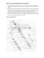
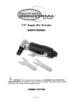
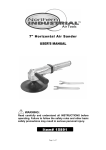
BLACK NICKEL
1/4" AIR ANGLE DIE GRINDER
USER’S MANUAL
WARNING:
Read carefully and understand all INSTRUCTIONS before
operating. Failure to follow the safety rules and other basic
safety precautions may result in serious personal injury.
It e m # 1 2 0 2 0 6
Page: 1 of 7
For technical questions and replacement parts, please call 1-800-222-5381.
Thank you very much for choosing a NORTHERN TOOL + EQUIPMENT CO., INC.
Product! For future reference, please complete the owner’s record below:
Model: _______________
Purchase Date: _______________
Save the receipt, warranty and these instructions. It is important that you read the
entire manual to become familiar with this product before you begin using it.
This machine is designed for certain applications only. Northern Tool + Equipment
strongly recommends that this machine is not modified and/or used for any
application other than that for which it was designed. If you have any questions
relative to a particular application, DO NOT use the machine until you have first
contacted Northern Tool + Equipment to determine if it can or should be performed
on the product.
Before using this product, please read the following instructions carefully.
Technical Specifications
Item
Collet Capacity
Rated Speed
Max. Air Pressure
Air Consumption
Air Inlet Diameter
Min. Hose Size
Accessories
Description
1/4"
22,000 RPM
90 PSI Recommended
4 CFM
1/4"- 18NPT
3/8"
Collet nut wrenches (2 pcs.)
SAVE THIS MANUAL
You will need this manual for the safety warnings and precautions, assembly, operating,
inspection, maintenance and cleaning procedures, parts list and assembly diagram. Keep this
manual and invoice in a safe and dry place for future reference.
WARNING!
Some dust created by power sanding, sawing, grinding and other construction activities
contains chemicals known to cause cancer, birth defects, or other reproductive harm. Some
examples off these chemicals are:
• Lead from lead-based paints
• Crystalline silica form bricks, cement and other masonry products
• Arsenic and chromium from chemically treated lumber
Your risk from exposure varies, depending now how often you do this type of work. To reduce
your exposure to these chemicals: work in a well-ventilated area, and use approved personal
protective equipment such as dust masks that are specially designed to filter out microscopic
particles.
GENERAL SAFETY RULES
Page: 2 of 7
Read and understand all instructions.
Failure to follow all instructions listed in the following pages may result in electric shock, fire,
and/or serious injury.
Work Area
1. Keep your work area clean and well lit. Cluttered benches and dark areas invite
accidents.
2. Do not operate pneumatic tools in explosive atmospheres, such as in the presence
of flammable liquids, gases, or dust. Pneumatic tools create sparks which may ignite
flammables.
3. Keep bystanders, children and pets away while operating a pneumatic tool.
Distractions can cause you to lose control. Protect others in the work area from debris such
as metal filings and sparks. Provide barriers or shields as needed.
Personal Safety
1. Stay alert. Watch what you are doing, and use common sense when operating a
pneumatic tool. Do not use a pneumatic tool while tired or under the influence of drugs,
alcohol, or medication. A moment of inattention while operating pneumatic tools may result
in serious personal injury.
2. Dress properly. Do not wear loose clothing or jewelry. Keep your hair, clothing, and gloves
away from moving parts. Loose clothes, jewelry, or long hair can be caught in moving parts.
3. Avoid accidental starting. Be sure the trigger is off before connecting to the air supply.
Carrying pneumatic tools with your finger on the trigger, or connecting pneumatic tools to
the air supply with the trigger on, invites accidents.
4. Remove adjusting keys or wrenches before turning on the tool. A wrench or a key that
is left attached to a rotating part of the tool may result in personal injury.
5. Do not overreach. Keep proper footing and balance at all times. Proper footing and
balance enables better control of the tool in unexpected situations.
6. Use safety equipment. Always wear ANSI-approved safety glasses underneath a full face
shield, and hearing protection.
Use and Care
1.
Use clamps or other practical ways to secure and support the workpiece to a stable
platform. Holding the work by hand is unstable and may lead to loss of control. Only work
on a workpiece that is properly secured.
2.
Do not force the tool. Use the correct tool for your application. The correct tool will do the
job better and safer at the rate for which it is designed.
3.
Do not use the power tool if the trigger does not turn it on or off. Any tool that cannot be
controlled with the trigger is dangerous and must be replaced.
4.
Disconnect the air hose from the tool before making any adjustments, changing
accessories, or storing the tool. Such preventive safety measures reduce the risk of
starting the tool accidentally.
5.
Store idle tools out of reach of children and other untrained persons. Tools are dangerous
in the hands of untrained users.
6.
Maintain tools with care. Do not use a damaged tool. Tag damaged tools “Do not use” until
repaired.
Page: 3 of 7
7.
Check for misalignment or binding of moving parts, breakages of parts, damaged air hose
(not included), and any other condition that may affect the tool’s operation. If damaged,
have the tool serviced before using. Many accidents are caused by poorly maintained
tools.
8.
Use only accessories that are recommended by the manufacturer for your model.
Accessories that may be suitable for one tool may become hazardous when used on
another tool.
Service
1.
Tool service must be performed only by qualified repair personnel. Service or maintenance
performed by unqualified personnel could result in a risk of injury.
2.
When servicing a tool, use only identical replacement parts. Follow instructions in the
“Inspection, Maintenance and Cleaning” section of this manual. Use of unauthorized parts
or failure to follow maintenance instructions may create a risk of injury.
SPECIFIC SAFETY RULES
1. To avoid accidental injury, always wear ANSI-approved safety glasses, a full face shield,
and hearing protection when operating the Die Grinder.
2. Use clean, dry, regulated compressed air at 90 PSI. Do not exceed the recommended 90
PSI. Never use oxygen, carbon dioxide, combustible gases, or any other bottled gas as a
power source for this tool.
3. When connecting to the air supply: Prior to each use, if an automatic oiler is not used, add
two drops of air tool oil (not included) into the air inlet fitting of the Die Grinder.
4. Always disconnect the Die Grinder from its compressed air supply source, and squeeze the
trigger to release all compressed air in the tool before performing any maintenance or
service.
5. The warnings, precautions, and instructions discussed in this manual cannot cover all
possible conditions and situations that may occur. The operator must understand that
common sense and caution are factors which cannot be built into this product, but must be
supplied by the operator.
ASSEMBLY AND OPERATING INSTRUCTIONS
To attach a quick connector
WARNING! Prior to performing any assembly and/or adjustment procedures, make
sure the air supply hose (not included) is disconnected from the Die Grinder.
1. Prior to use, the Die Grinder requires the attachment of a quick-connector into its air inlet.
To do so, wrap approximately 3" of pipe thread sealer tape (not included) around the male
threads of a quick-connector. Then, firmly tighten the quick-connector into the air inlet.
Page: 4 of 7
Fig. 1
To Operate as a 1/4" Die Grinder:
1. Always wear ANSI-approved safety glasses, a full face shield, and hearing protection
when operating the tool.
2. Use the two wrenches provided to loosen the collet nut.
3. Insert the 1/4" diameter shank of a grinding drum (not included) fully into the collet. Then,
firmly re-tighten the collet nut to lock both the collet and grinding drum in place.
4. Connect the air supply hose to the quick-connector on the Die Grinder. Turn on the air
compressor, and set its regulator to the recommended 90 PSI for the Die Grinder.
5. IMPORTANT! Grip the appliance firmly with BOTH hands.
6. Trip the safety with your finger. Then slowly apply hand pressure to the trigger until the
desired speed is obtained. NOTE: The tool always turns the Grinding Drum/Drill Chuck
clockwise. (See fig. 2)
TRIGGER
SAFETY
Fig. 2
7. With a firm grip on the Die Grinder, lightly apply the Grinding drum to the workpiece, slowly
and steadily moving the grinding drum to the right and left until you have achieved the
desired appearance (finish) on the workpiece.
8. Once the work is completed, release hand pressure on the trigger, the safety will
automatically return to its locked position to prevent the trigger from accidentally being
activated.
9. Turn off the air compressor. Trip the safety with your finger, and slowly squeeze the trigger
to release any remaining air pressure from the die grinder. Then disconnect the air hose
from the tool.
10. Remove the grinding drum from the Die Grinder. Then store the tool in a clean, dry location
out of reach of children and untrained operators.
Page: 5 of 7
INSPECTION, MAINTENANCE AND CLEANING
1. Always make sure the trigger is in its “OFF” position, and disconnect the Die Grinder from
its compressed air supply before performing any inspection, adjustments, maintenance, or
cleaning.
2. Before each use, inspect the general condition of the Die Grinder. Check for loose screws,
misalignment or binding of moving parts, cracked or broken parts, damaged air hose, and
any other condition that may affect its safe operation. If abnormal noise or vibration occurs,
have the problem corrected before further use. Do not use damaged equipment.
3. Daily: With a clean cloth, remove all dirt, oil, and grease from the Die Grinder. If necessary,
you may use a mild detergent. Do not use solvents, as damaged to the Die Grinder may
occur. Do not immerse the Die Grinder in any liquids.
Diagram & PARTS LIST
Page: 6 of 7
Part#
Description
Qty.
Part#
Description
Qty.
1
Housing
1
18
Air Inlet
1
2
Valve Bushing
1
19
Washer
1
3
Valve Stem
1
20
Collet Holder
1
4
Trigger
1
21
Collet
1
5
Air Regulator
1
22
Cap
1
6
Pin
1
23
Retainer
1
7
Valve Plug
1
24
Housing Cap
1
8
O-ring
1
25
Muffle Cover
1
9
End Plate
1
26
Wrench
1
10
Bearing
1
27
Wrench
1
11
Steel Ball
1
28
O-ring
1
12
Rotor
1
29
O-ring
1
13
Rotor Blade
1
30
Spring
1
14
Cylinder
1
31
Pin
1
15
Front Plate
1
32
Lever
1
16
Bearing
1
33
O-ring
1
17
Spring
1
34
Washer
1
Northern Tool + Equipment Co.,
2800 Southcross Drive West
P.O. Box 1499 Burnsville, MN 5337-0499
Made in China.
Page: 7 of 7