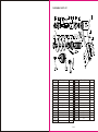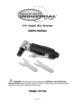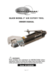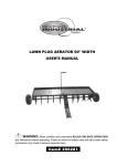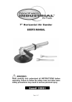
1
WARNING
Some dust created by power sanding, sawing, grinding, drilling, and other construction
activities contains chemicals known to the State of California to cause cancer, birth
defects or other reproductive harm. Some examples of these chemicals are:
lead from lead-based paints,
crystalline silica from bricks and cement and other masonry products, and
arsenic and chromium from chemically treated lumber.
Your risk from these exposures varies, depending on how often you do this type of work.
To reduce your exposure to these chemicals: work in a well-ventilated area, and work with
approved safety equipment, such as those dust masks that are specially designed to filter
out microscopic particles.
5in. HIGH SPEED
AIR SANDER/DRILL COMBO
USER'S MANUAL
Distributed by
Northern Tool + Equipment Co., Inc.
2800 Southcross Drive West
Burnsville, MN 5337-0499
Made in China.
6 of 6
WARNING:
Read carefully and understand all INSTRUCTIONS before operating. Failure to follow
the safety rules and other basic safety precautions may result in serious personal injury.
Item# 1991202
Note: To connect this tool, we recommend a quick coupler/adapter (not included).
For smoother operation, put 3-5 drops of pneumatic tool oil in the Hose Joint (6)
before each use.
Step 1: Set the compressor's pressure regulator to 90 PSI. Do not set the compressor's
outlet regulator over 90 PSI.
Step 2: Connect the Sander/Drill to the air compressor's hose. If leaking is detected,
disconnect the air hose and repair before use.
DRILLING
Step 1: Mark the material you wish to drill at the spot for the hole. Make sure your drill bit
is the correct size for the hole you need to make.
Step 2: If possible, clamp the material in a vise to make sure the material does not move
or begin to spin while drilling.
Step 3: Wear eye protection to guard against flying wood or metal.
Step 4: Set the compressor's pressure regulator to 90 PSI. Do not set the compressor's
outlet regulator over 90 PSI.
Step 5: Connect the Sander/Drill to the air compressor's hose. If leaking is detected,
disconnect the air hose and repair before use.
Step 6: Grip the Sander/Drill firmly. Place the drill bit on the spot marked in Step 1.
Step 7: To begin drilling, press the TRIGGER (10).
Step 8: Your Sander/Drill has a variable speed for drilling. To vary the speed of the drilling
action, vary the pressure on the TRIGGER.
Step 9: Drill only as deep as necessary. Do not drill into walls or other areas where you
cannot identify any possible hazards behind the drilling surface.
Step 10: When you have drilled the hole, remove the drill bit from the hole while the
Sander/Drill is still spinning. This is to prevent the drill getting caught in the hole and
causing damage.
For technical questions and replacement parts, please call 1-800-222-5381.
Thank you very much for choosing a Wel-BiltTM, Product! For future reference, please
complete the owner's record below:
Model: _______________ Purchase Date: _______________
Save the receipt, warranty and these instructions. It is important that you read the entire
manual to become familiar with this product before using it.
This machine is designed for certain applications only. The distributor strongly
recommends that this machine is not modified and/or used for any application other than
that for which it was designed. If you have any questions relative to a particular
application, DO NOT use the machine until you have first contacted Northern Tool +
Equipment to determine if it can or should be performed on the product.
Before using this product, please read the following instructions carefully.
TECHNICAL SPECIFICATIONS
Item
Description
Item
Free Speed
18,000 RPM
Air Inlet Diameter
1/4in.- 18NPT
Chuck Type
3/8in. Jacobs Chuck
Disc Size
Air Consumption
3in., 4-1/2in., 5-1/2in.
Max. Air Pressure
4 CFM
Description
R
90 PSI
SAVE THIS MANUAL
You will need this manual for the safety warnings and precautions, assembly, operating,
inspection, maintenance and cleaning procedures, parts list and assembly diagram. Keep
this manual and invoice in a safe and dry place for future reference.
SAFETY RULES
SANDING
Step 1: Identify the area you will be sanding. Make sure you are using the appropriate grit
sandpaper for the material you will be working with.
Step 2: It is recommended that you start the Sander/Drill before placing the sandpaper
disc onto the work surface. This will reduce deep scratching in the surface.
Step 3: To operate the Sander/Drill, grip the BODY (1) with your palm and place pressure
on the TRIGGER (10) to begin sanding.
Step 4: You can vary the speed of the Sander/Drill to suit different sanding applications by
varying the pressure placed on the TRIGGER.
Step 5: It is recommended that you sand in a random pattern to avoid sanding a side to
side into your work surface. Do not sand any one area too heavily, or for more than a few
seconds at a time.
Step 6: Every few minutes during continuous sanding, check the condition and wear of the
sandpaper. If necessary, peel and replace the sandpaper. Do not use torn or severely
worn sandpaper, you may damage your work surface or suffer physical injury.
Step 7: When you are done sanding, remove the Sander/Drill from the work surface and
release pressure on the TRIGGER to stop the Sander/Drill.
Read all instructions before using this tool!
1.Keep work area clean. Cluttered areas invite injuries.
2.Observe work area conditions. Do not use machines or power tools in damp or wet
locations. Don't expose to rain. Keep work area well lighted. Do not use electrically
powered tools in the presence of flammable gases or liquids.
3.Keep pets, untrained operators and children away. Children must never be allowed
in the work area. Do not let them handle machines, tools, or extension cords.
4.Store idle equipment. When not in use, tools must be stored in a dry location to inhibit
rust. Always lock up tools and keep out of reach of children.
5.Use the right tool for the job. Do not attempt to force a small tool or attachment to do
the work of a larger industrial tool. There are certain applications for which this tool was
designed. It will do the job better and more safely at the rate for which it was intended. Do
not modify this tool and do not use this tool for a purpose for which it was not intended.
MAINTENANCE
Your Sander/Drill is best operated with an Airline Oiler. If you are using the Sander/Drill
without an Airline Oiler, follow the steps below for maintenance.
Step 1: Disconnect the Sander/Drill from the air hose.
Step 2: Apply a few drops of PNEUMATIC TOOL OIL through the air line before each use,
or every hour if used continuously.
Step 3: Apply a few drops of oil to the TRIGGER (10). Work the TRIGGER a few times to
lubricate.
4 of 6
1 of 6
DIAGRAM & PART LIST
Part#
Description
Qty.
Part#
Description
1
Body
1
17
Cylinder
1
2
Control Pin
1
18
Vanes
4
3
Rubber Gasket
1
19
Rotor
1
4
Ball
1
20
Bushing
1
5
Spring
1
21
Front End Plate
1
6
Hose Joint
1
22
Spacer
1
7
Rubber Gasket
1
23
Bearing
1
8
O-Ring
1
24
Cylinder Housing
1
9
Regulator
1
25
Sanding Adapter
1
10
Trigger
1
26
Holding Tool
1
11
Pin
1
27
Adapter Lock Down
1
12
Pin
1
28
Backing 3" Plate
1
13
Housing Lock Ring
1
29
Backing 4-1/2" Plate
1
14
Bearing
1
30
Backing 5-1/2" Plate
1
15
Spacer
1
31
Chuck
1
16
Rear End Plate
1
5 of 6
Qty.
6.Dress properly. Do not wear loose clothing or jewelry as they can be caught in moving
parts. Protective, electrically non-conductive clothes and non-skid footwear are
recommended when working. Wear restrictive hair covering to contain long hair.
7.Use eye protection. Always wear ANSI-approved impact safety goggles. Wear a full
face shield if you are producing metal filings or wood chips. Wear an ANSI-approved dust
mask or respirator when working around metal, wood, and chemical dusts and mists.
8.Do not overreach. Keep proper footing and balance at all times. Do not reach over or
across running machines.
9.Maintain tools with care. Keep tools clean for better and safer performance. Follow
instructions for changing accessories. Inspect tool periodically and if any part appears
broken or damaged, have it repaired by an authorized technician. The handles must be
kept clean, dry, and free from oil and grease at all times.
10.Disconnect power. Disconnect tool from air compressor when not in use and before
changing accessories, maintaining, repairing, or cleaning.
11.Remove adjusting keys and wrenches. Check that adjusting wrenches are removed
from the tool or machine work surface before connecting it to its power source.
12.Avoid unintentional starting. Be sure the air compressor switch is in the Off position
when not in use and before connecting to this tool. Do not carry any tool with your finger
on the trigger, whether it is connected or not.
13.Take caution as some woods contain preservatives such as copper chromium
arsenate (CCA) which can be toxic. When cutting these materials extra care should be
taken to avoid inhalation and minimize skin contact.
14.Check for damaged parts. Before using any tool, any part that appears damaged
should be carefully checked to determine that it will operate properly and perform its
intended function. Check for alignment and binding of moving parts; any broken parts;
and any other condition that may affect proper operation. Any part that is damaged should
be properly repaired or replaced by a qualified technician. Do not use the tool if the trigger
does not operate properly.
15.Guard against electric shock. Prevent body contact with grounded surfaces such as
pipes, radiators, ranges, and refrigerator enclosures.
16.Do not operate tool if under the influence of alcohol or drugs, or if you are tired.
This may result in serious injury.
17.Use proper size and type extension cord. If an extension cord is required for the
compressor, it must be of the proper size and type to supply the correct current to the tool
without heating up. Otherwise, the extension cord could melt and catch fire, or cause
electrical damage to the tool.
18.Maintenance. For your safety, service and maintenance should be performed
regularly by a qualified technician.
19.Use clean, dry, regulated, compressed air at 90 PSI. Do not exceed the
recommended 90 PSI. Never use oxygen, carbon dioxide, combustible gases, or any
other bottled gas as a power source for this tool.
Note: Performance of the compressor powering this tool (if powered by line voltage) may
vary depending on variations in local line voltage. Extension cord usage may also affect
compressor performance.
ASSEMBLY
DRILL BIT INSTALLATION
Backing Plate
CAUTION: Disconnect the
Sander/Drill from the Air Supply
prior to cleaning, maintaining,
Adapter Lock Down
or making any adjustments to
The tool.
Step 1: Thread the ADAPTER LOCK DOWN (27)
counterclockwise to loosen it and remove the backing
plate.
Step 2: Thread the drill chuck onto the SANDING
ADAPTER (25)
Step 3: Open up the jaws of the drill by turning the
CHUCK (31) counterclockwise as shown in Figure 2.
Step 4: When the jaws are open wide enough to insert
the drill bit (See Fig. 3), slide the bit into the CHUCK
As far as possible.
Step 5: By hand, turn the CHUCK to tighten the jaws.
Step 6: Insert the Chuck Key into one of the three
Chuck holes in the DRILL CHUCK, mating the teeth of
the Chuck Key with the teeth of the DRILL CHUCK.
Step 7: Turn the Chuck Key to tighten the jaws
clockwise as shown in Fig. 4. Make sure the jaws are
tight.
Step 8: Put the Chuck Key in a safe place. Do not lose
the Chuck Key.
Fig 1
Fig 2
REMOVE THE CHUCK
Step 1: Open the CHUCK (31) by turning the CHUCK
counterclockwise. Insert the short end of a Hex Key
Wrench into the CHUCK and tighten.
Step 2: Place the HOLDING TOOL (26) into one of the
two holes in the SANDING ADAPTER (25). See Fig. 5
Step 3: Turn the Hex Key Wrench counterclockwise to
loosen the CHUCK. You may gently tap on the end of
Holding Tool
Fig 3
Fig 4
Hex Key
Fig 5
the Hex Key Wrench with a rubber mallet (not included).
Step 4: Remove the CHUCK.
SANDER ASSEMBLY
Disconnect the Sander/Drill from the Air Supply prior to cleaning, maintaining, or
making any adjustments to the tool.
Step 1: Tread the ADAPTER LOCK DOWN (27) clockwise to loosen it and remove out.
Step 2: You will need sandpaper discs the appropriate size for the Backing Plate you will
be using.
Step 3: Place the desired BACKING PLATE (28, 29, or 30) over the threads of the ROTOR
(19). Place the sandpaper disc over the BACKING PLATE.
Step 4: Thread the ADAPTER LOCK DOWN (27) onto the ROTOR as shown in Figure 1.
Tighten.
2 of 6
SET UP
Fig. 6
3 of 6