1
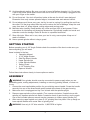
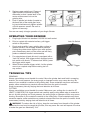
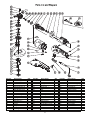
41/2"
ANGLE GRINDER
OPERATING MANUAL
Item # 143379
READ ALL INSTRUCTIONS BEFORE OPERATING
SAVE THESE INSTRUCTIONS
Before attempting to operate your new Angle Grinder please read these instructions
thoroughly. You will need these instructions for the safety warnings, precautions, assembly,
operation, maintenance procedures, parts list and diagrams.
WARNING: The warnings, cautions and instructions discussed in this instruction manual
cannot cover all possible conditions or situations that could occur. It must be understood by
the operator that common sense and caution are factors which cannot be built into this
product, but must be supplied by the operator.
TABLE OF CONTENTS
Description
Page #
Warranty..............................................................1
Specifications......................................................1
Safety rules .......................................................1-2
Getting Started....................................................3
Assembly ............................................................3
Operating Your Grinder.......................................4
Tech Tips.............................................................4
Maintenance .......................................................5
Parts List and Diagram .......................................6
SPECIFICATIONS
Motor ......................................120V~ 60Hz – 8amp
No Load Speed....................................11,000 RPM
Weight ..............................................................7 lbs
Overall Length .................................................16.5"
Spindle Thread ..................................5/8" - 11 UNC
SAFETY RULES
WARNING: The double-insulated system is intended to protect the user from shock
resulting from a break in the tool's internal wiring. Observe all normal safety precautions related to avoiding electric shock.
1.
2.
Know your machine. Read this manual carefully. Learn the machine’s applications and
limitations, as well as specific potential hazards peculiar to it.
Ground all machines. This machine is “Double Insulated,” meaning that all outside metal
parts are insulated from electrical power. Double Insulated tools are equipped with a
polarized plug. This plug will fit in a polarized outlet only one way. If the plug does not fit
fully in the outlet, reverse the plug. If it still does not fit, contact a qualified electrician to
install a polarized outlet. Do not attempt to circumvent this safety feature.
1
3.
4.
5.
6.
7.
8.
9.
Do not expose tool to moisture. Don’t use this machinery in damp or wet locations. Keep
out of rain.
Keep work area clean. Cluttered areas invite injuries.
Keep children and pets away. All children should be kept away from the work area. Never
let a child handle a tool without strict adult supervision.
Do not operate this tool if under the influence of alcohol or drugs or if you are tired. Read
warning labels on prescriptions to determine if your judgment or reflexes are impaired
while taking drugs. If there is any doubt, do not attempt to operate.
Use safety equipment. Eye protection should be worn at all times when operating this
machine. Use ANSI approved safety glasses. Everyday eyeglasses only have impact
resistance lenses. They are NOT safety glasses. Dust mask, respirator, non-skid safety
shoes, hard hat, or hearing protection must be used in appropriate conditions.
Wear proper apparel. Loose clothing, gloves, neckties, rings, bracelets, or other jewelry
may present a potential hazard when operating this machine. Please keep all apparel
clear of the machine.
Don’t overreach. Keep proper footing and balance at all times when operating this product.
10. Always disconnect the machine from power source before servicing or changing accessories.
11. Check for damage. Check your tool regularly. If part of the tool is damaged it should be
carefully inspected to make sure it can perform its intended function correctly. If in doubt,
the part should be repaired. Refer all servicing to a qualified technician. Consult your
dealer for advice.
12. Keep away from flammables. Do not attempt to operate this tool near flammables or combustibles. Failure to comply may cause serious injury or death.
13. Do not start tool while it is resting on materials. Always turn tool on BEFORE coming in
contact with material surface.
14. Do not set tool down until it has come to a complete stop.
15. Always check to make sure that trigger is not engaged before plugging tool in.
16. Keep hands clear of cutting edges and all moving parts.
17. Protect others in work area from debris such as chips and sparks. Provide barriers and
shields as needed.
18. Secure work. Use a clamp, vise or other practical means to hold your work securely,
freeing both hands to control the tool.
19. Use the right tool for the job. Do not use a tool or attachment to do a job for which it was
not intended. Do not alter a tool.
20. Use proper accessories. Using accessories not recommended may be hazardous. Be sure
accessories are properly installed and maintained. Do not defeat a guard or other safety
device when installing an accessory or attachment.
21. Remove all adjusting keys and wrenches. Make a habit of checking that adjusting keys,
wrenches, etc. are removed from the tool before turning it on.
22. Guard against electric shock. Prevent body contact with grounded surfaces such as
pipes, radiators, ranges, and refrigerators. Hold your tool by insulated, non-metal grasping surfaces. Use a Ground Fault Circuit Interrupter (GFCI) to reduce shock hazards.
2
23. Avoid accidental starting. Be sure your tool is turned off before plugging it in. Do not use
a tool if the power switch does not turn the tool on and off. Do not carry a plugged-in tool
with your finger on the switch.
24. Do not force tool. Your tool will perform better at the rate for which it was designed.
Excessive force only causes operator fatigue, increased wear and reduced control.
25. Do not abuse cord. Never carry your tool by its cord or unplug it by pulling the cord from
the outlet. Pull the plug rather than the cord to reduce the risk of damage. Keep the cord
away from heat, oil, sharp objects, cutting edges and moving parts.
26. Maintain tools carefully. Keep handles dry, clean and free from oil and grease. Follow
instructions for lubricating and changing accessories. Periodically inspect tool cords and
extension cords for damage. Refer all service to a qualified technician.
27. Store idle tools. When not in use, store your tool in a dry, secure place. Keep out of
reach of children.
28. Never operate grinder without using a guard.
GETTING STARTED
Before operating your 4-1/2" Angle Grinder check the contents of the box to make sure you
have everything you will need.
Items included in the box:
1 Operating Manual
1 4-1/2" Angle Grinder
1 Side/Top Mount Handle
1 Upper Spindle Nut
1 Lower Spindle Washer
1 Safety Guard
1 4-1/2" Grinding Disc
1 Spanner Wrench
Follow these instructions closely to insure optimum results.
ASSEMBLY
WARNING! Your grinder should never be connected to power supply when you are
assembling parts, making adjustments, installing or removing grinding wheels, or when not
in use.
1. Choose the most comfortable position for your side/top mount handle. Screw the handle
securely into one of the three handle ports located at the base of the gear housing.
2.
Make sure tool is unplugged and lay it on its back with the spindle upright.
4.
After removing upper spindle nut, place 4-1/2" grinding disc into place. Line up flange on
lower spindle washer with center hole of grinding disc.
3.
Remove upper spindle nut from spindle. (Turn counter clockwise. If spindle turns with
spindle nut, depress spindle lock button -located on back of gear housing- and try again.
Use of the included spanner wrench may be necessary to loosen upper spindle nut.)
WARNING: Use only 4-1/2" disc rated for 11,000 RPM or higher.
3
5.
6.
Replace upper spindle nut. Flange of
upper spindle nut should be facing
downward so that it seats itself in the
center reinforcement hub on the
grinding disc.
Push in spindle lock button (located on
the back side of the metal gear housing) and simultaneously tighten spindle
nut with spanner wrench. Be sure to
tighten nut securely.
You are now ready to begin operation of your Angle Grinder.
OPERATING YOUR GRINDER
1.
Plug Angle Grinder into standard 110/120 Volt wall socket.
3.
Evenly and carefully, lower grinding disc surface to
material surface. Do not apply excessive pressure.
Forcing the grinder down against your work surface
puts unnecessary strain on the motor and will likely
produce undesired results in workmanship.
2.
5.
6.
Prior to contact with material surface, pull trigger
switch to ON position.
For extended work loads this tool is equipped with a
“lock ON” switch. With trigger switch engaged, press
lock switch with thumb. To release lock switch, press
the trigger switch again.
When finished release trigger switch. Let the grinder
come to a complete stop before resting tool on
any surface.
Lock On Switch
ON/OFF Trigger
TECHNICAL TIPS
GRINDING
Always use side/top mount handle for control. Move the grinder back and forth in sweeping
strokes. Too much pressure, the wrong angle or improper motion may cause burning. Be
aware of your material’s reaction to the grinding disc. Some materials may throw excessive
sparks; some materials may conduct extreme heat from the point of contact.
Avoid unnecessary risks by staying alert and attentive at all times.
CUTTING
Always use side/top mount handle for control. Make sure your cutting disc is rated for AT
LEAST 11,000 RPM. Pull trigger switch and carefully apply cutting blade edge to material to
be cut. As with grinding, too much pressure, the wrong angle or improper motion may cause
burning. Be aware of your material’s reaction to the cutting disc. Some materials may throw
excessive sparks; some materials may conduct extreme heat from the point of contact. Avoid
unnecessary risks by staying alert and attentive at all times.
WARNING: To reduce the risk of injury, keep the cord away from the path of the grinder.
Otherwise the cord may be caught by the disc; this may sever the cord and expose live wires
or make the gear box electrically “live.”
4
MAINTENANCE
Keep your tool in good condition by adopting a regular maintenance program. Before use,
examine the general condition of your tool. Inspect guards, switches, tool cord and extension
cord for damage. Check for loose screws, misalignment, binding of moving parts, improper
mounting, broken parts, and any other condition that may affect its’ safe operation. If
abnormal noise or vibration occurs, turn the tool off immediately and have the problem
corrected before further use. Do not use a damaged tool.
WARNING: To reduce the risk of injury, always unplug your tool before performing any
maintenance. Never disassemble the tool or try to do any rewiring on the tool’s electrical
system. Contact Northern for all repairs.
CLEANING
Clean dust and debris from vents. Keep the tool handles clean, dry and free of oil or grease.
Use only mild soap and damp cloth to clean your tool since certain cleaning agents and
solvents are harmful to plastics and other insulated parts. Some of these harmful solvents
include: gasoline, turpentine, lacquer thinner, paint thinner, chlorinated cleaning solvents,
ammonia, and household detergents containing ammonia. Never use flammable or
combustible solvents around tools.
WARNING: To reduce the risk of injury, electric shock and damage to the tool, never
immerse your tool in liquid or allow liquid to flow inside the tool.
5
Part No.
01
02
03
04
05
06
07
08
09
10
11
12
13
14
15
16
17
18
19
Description
Outer Flange
Inner Flange
Hex Screw
Screw
Spring Washer 04
Spring Washer 05
Disc Guard Cover
Disc Guard
Spindle
Stop Bearing
Screw
Spring Washer
Gear Housing Cover
Ball Bearing
Flat Washer
Circlip
Large Gear
Circlip
Bushing
Qty.
1
1
1
3
3
1
1
1
1
1
4
4
1
1
1
1
1
1
1
Part No.
20
21
22
23
24
25
26
27
28
29
30
31
32
33
34
35
36
37
38
Description
Screw
Gear Housing
e-ring
Brake Spring
Brake Pin
Side Handle
Nut
Pinion
Ball Bearing
Bearing Cover
Sink Screw
Key
Armature
Ball Bearing
Bushing
Guide Wind Circle
Screw
Stator
Screw
6
Qty.
4
1
1
1
1
1
1
1
1
1
2
1
1
1
1
1
2
1
2
Part No.
39
40
41
42
43
44
45
46
47
48
50
51
52
53
54
55
56
57
Description
Screw
Screw
Rear Handle (right)
ON/OFF Switch
Cord Sleeve
Power Cord
Switch Trigger
Screw
Cord Clamp
Rear Handle (left)
Carbon Brush
Screw
Spec Plate
Brush Holder
Housing
Name Plate
Wrench
Grinding Disc
Qty.
1
1
1
1
1
1
1
2
1
1
2
4
1
2
1
1
1
1