1
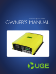
UGE-4K Off-Grid Controller
OWNER’S MANUAL
CONTENTS
INTRODUCTION ..................................................................................................................................
3
PARTS LIST .................................................................................................................................................. 4
SPECIFICATIONS ....................................................................................................................................
5
SAFETY INSTRUCTIONS.................................................................................................................... 6-7
INSTALLATION ....................................................................................................................................... 8
MOUNTING GUIDE ..................................................................................................................
9
WIRING DIAGRAM ................................................................................................................................. 10
CONTROLLER INTERFACE ..............................................................................................................
11
WIRING INSTRUCTIONS ................................................................................................................
14
SYSTEM START-UP ................................................................................................................................... 15
OPERATION & MAINTENANCE .................................................................................................. 16
diversion load operation..................................................................................................
17
LCD DISPLAY ............................................................................................................................................... 18
NOTES.............................................................................................................................................................. 19
TECHNICAL SUPPORT ..................................................................................................................... Back
2
INTRODUCTION
Dear UGE-4K Owner,
Congratulations on purchasing your Urban Green Energy (UGE) 4kW rated Vertical Axis Wind Turbine (VAWT) and
Off Grid Controller and welcome to our family.
Enclosed in this manual is information regarding installation, operation and maintenance of the controller. Please read
through the manual in its entirety before installing and using your turbine and controller. Under certain circumstances
this information may not be fully comprehensive and additional instruction or information may be required in order
to successfully and safely complete the installation.
These installation and maintenance instructions contain important information for the safe installation and maintenance
of the UGE-4K off grid controller. Designed for use with the UGE-4K VAWT, the function of the controller is to
take the variable 3-phase AC output from the permanent magnet generator in the wind turbine and convert it to a
stable 48 V DC output to charge a battery bank. The controller also manages the turbine so that it performs safely
and optimally.
The controller should only be installed by qualified personnel such as an employee of a UGE distributor or a certified
electrician. Yearly maintenance checks should be performed by qualified personnel. The owner should retain a copy
of this manual for reference and to give to future maintenance personnel.
This manual should be used in conjunction with turbine installation manual, and the UGE Electrical Supplement.
These manuals can be found on the website of the tower and electronics suppliers respectively or can be provided
by your UGE distributor.
We would like to hear from you with any questions or comments that you have. Please contact us during working
hours (Monday-Friday 9:00am to 6:00 pm - US Eastern Time) at:
Telephone: +1 (917) 720-5685
Website: www.urbangreenenergy.com
Email: [email protected]
Sincerely,
3
PARTS LIST
325
Check the Charge Controller and Parts
Please check all the parts based on the following instructions when receiving the package. Contact your local
dealer if any part is missing.
400
x1 Controller
325mm
400
130
130mm
400mm
325
x1 Diversion Load
200
600mm
130
600
200
900mm
185mm
Charge Controller * 1
x3 Cable Gland
Cable Glands *3
User Manual * 1
200
4
900
900
SPECIFICATIONS
Output Voltage ............................................................................................................................................................................ 48V
Input Voltage Range (line to line voltage) .................................................................................................. 50-230Vrms
Charge Start/Stop Voltage (Iine to line voltage) ........................................................................... 50Vrms/45Vrms
Rated Input Current ................................................................................................................................................................. 20A
Maximum Charge Efficiency/MPPT Efficiency ........................................................................................ >85%/>90%
Standby Consumption ......................................................................................................................................................... <5W
Floating Charge Voltage ...................................................................................................................................... 55.2Vdc ±1V
Over-charge Protection .......................................................................................................................................... 57.6V ±1V
Discharge Stop Voltage ............................................................................................................................................46Vdc ±1V
Battery Sleep Mode Voltage ..................................................................................................................................40Vdc ±1V
Max. Charge Current ........................................................................................................................................................... 62.5A
Load Connection ............................................................................. Dry Contact, Can turn on a DC/AC inverter.
User Interface ........................................................................................................................................ LCD status indicators
Operating Temperature ....................................................................................................................................... -20ºC~40ºC
Controller
Dimension (L × W × H) mm ................................................................................................... 400 x 325 x 130
Weight ............................................................................................................................................................................... 15kg
IP Grade ............................................................................................................................................................................ IP43
Diversion Load
Dimension (L × W × H) mm ................................................................................................... 900 x 600 x 185
Weight ............................................................................................................................................................................... 38kg
IP Grade ............................................................................................................................................................................ IP43
5
Safety instructions
The charge controller shall be installed and operated in accordance with the instructions in this User Manual.
The following conventions are used in this guide:
WARNING
Warnings identify conditions that could cause personal
injury, loss of life, or serious damage to the unit or other
equipment.
CAUTION
Warnings identify conditions or practices that could cause
personal injury or damage to the unit.
1. The UGE-4K-OGC and supported diversion load should be installed indoors or a dry
place that avoids direct sunlight, rain and snow and has good ventilation. Do not leave
anything heavy on top of the controller.
2. Keep the controller and battery away from flammables and items that can conduct
electricity.
3. Always use the controller with the supported diversion loads.
4. The diversion load cannot be covered by other items and cannot be placed within 300
mm (1 ft) of any flammable, heat sensitive, and/or explosive items.
5. If the controller or turbine behaves abnormally, use the safety brake to stop the wind
turbine and disconnect the controller from battery. Do not start the controller until you
have contacted UGE tech support and the observed issue is resolved.
6. When the wind speed is high, the temperature of the Diversion Load will be high.
7. If the wind turbine is allowed to spin at high speeds without electrical resistance, such
as when the electronics are not completely and properly installed, the turbine may be
“free-spinning” which can lead to extremely dangerous operation. ALLOWING YOUR
WIND TURBINE TO FREE SPIN WILL VOID YOUR WARRANTY. Make sure that unless
the turbine is fully operational, it is completely stopped either through electrical or
mechanical means.
6
8. Check the appearance of the charge controller before installation. Contact your local
dealer if any obvious damage is found.
Safety instructions
9. The weight of this controller is around 15kg. Always treat the charge controller with
caution during transportation and installation.
10. Do not install the controller in gusty weather conditions.
11. The controller should be mounted vertically against the wall. Do not mount the
controller on an angle (see page 9).
12. This controller is for use with the UGE-4K wind turbine only.
13. Connect the wires by following the wiring instrustions on page 12.
14. Follow the wire sizing guide provided in the wire connection diagram (see page 13).
15. It could damage the controller permanently if the controller and battery are not wired
properly, e.g. connecting the positive and negative polarities reversely.
16. Wires must be secured tightly to terminals to prevent causing a short or open circuit.
17. Ground the shell of this machine properly to avoid electrical shock.
18. Check whether the battery voltage is within the normal range before starting the
controller.
19. Do not connect the controller to batteries that will operate in voltage outside the
battery voltage range defined on the specification table, page 5.
20. Do not remove the warranty and/or serial number labels.
21. Keep this manual for your future reference.
7
INSTALLATION
Step 1
Check the installation location
- minimum 20cm (8 “) clear space around the machine is required for heat dissipation
Step 2
Mount the charge controller
8
INSTALLATION
Wall
Wall
Wall
Mounting Guide
Step 2.1
Step 2.2
Step 2.3
Put the controller against the
wall and mark the locations for
drilling (6 holes).
Drill 6 holes and place anchors
into those holes.
Fasten screws and secure the
controller.
CAUTION
The mounting method
in C is prohibited.
A B
C
9
WIRING DIAGRAM
Electrical System Overview
Detailed wiring diagrams are available from the UGE website or your UGE distributor.
UGE-4K
Bat t ery Back-Up
Wiring Diagram
See Table A
10 AWG
10 AWG
AC
Disconnect
3
Switch #1
UGE
Off-Grid
Controller
See Table A
10
10 AWG
Table B
Length
AWG
Length
AWG
10m
12
1m
2/0
50m
6
2m
2/0
100m
4
3m
150m
2
5m
4/0
4/0x2
Sub
Panel
AC
Disconnect
Switch #3
30A/240VAC
Notes:
Wire gauge recommendations based on NEC 310.16 for THHW copper wire below 100˚F
(A certified electrician shall verify wire gauge meets local electrical code)
2 Each grounded component shall have its own ground wire and connect at a common earth ground
3 AC disconnect switch #1 and the safety break should be nonfusible
1
See Table B
See Table B
AC
Disconnect
Magnum
Switch #2
MS4448PAE
10 AWG
Inverter/
10 AWG
Charger
120V
30A/240VAC
10 AWG
Voltage Drop
1.2 V (5%)
Diversion
Load
175A
14 AWG
Safety
Brake
(60 A) 3
Fuse
Battery
Bank
48V
14 AWG
18 AWG
18 AWG
18 AWG
18 AWG
60 A
240 V AC
Table A
10 AWG
10 AWG
18 AWG
See Table A
UGE-4K
18 AWG
Main
Panel
Grid
Meter
INSTALLATION
Controller Interface
Battery
Output
Terminals
Power Switch
Wind Turbine Input
Terminals - PE
LCD Display
Communication
Interface
11
INSTALLATION
BAT+ Terminal
Connect to the positive
polarity of a battery.
PE Terminal
For grounding.
L1, L2, and L3
Terminals
Connect to the
3-phase AC output
of a wind turbine.
N+ and N- Terminal
Block (RS-485)
Reserved for RS-485
communication.
B+ and B- Terminal Block (BAT)
B+ connects to the positive polarity of a battery;
B- connects to the negative polarity of a battery.
Both of them are for detecting battery voltage.
BAT- Terminal
Connect to the negative
polarity of a battery.
12
a1 and a2 Terminal
Block (STOP)
Communicate external
short-circuit brake signal.
b1 and b2 Terminal
Block (SLOW DOWN)
Communicate external
slow down signal.
D+ and D- Terminal Block (DISCHARGING)
The controller sends the load discharging signals, which
can turn on an AC inverter. Maximum current is 8Amp.
INSTALLATION
Diversion Load
Shut-Down
Switch
Power
Switch
Slow-Down
Switch
To Controller
To Wind Turbine
PE Terminal
For grounding.
To Batteries
Connect to only one
12V or 24V battery.
13
WIRING INSTRUCTIONS
This machine includes components carrying high voltage electricity that could
potentially cause serious personal injury or even loss of life. The controller shall only
be installed by a qualified professional such as a licensed Electrician or UGE distributor.
The wiring of the controller shall meet the requirements of the NEC or the local
electrical code.
Before starting installation, please make sure the input and output power both are shut
down to avoid electrical shock.
Do not mount the controller above the diversion load, since the heat may damage the
controller.
1. Connect the output of your wind turbine to L1, L2, L3 terminals with 14AWG wires. Make sure the wind
turbine is fully shut down during wiring.
Correct polarity must be observed when connecting the battery cables to the controller.
Use caution when connecting the battery leads to avoid shorting them together.
2. Connect BAT(+) lines, 10AWG*2 in RED, to the positive polarity of a battery and BAT(+) terminal. Battery
lines should be shorter than 5 meters. (16’ – 0”)
3. Connect BAT(-) lines, 10AWG*2 in BLACK, to the negative polarity of a battery and BAT(-) terminal. Adding
a no fuse breaker (NFB) to the battery circuit is highly recommended.
4. Connect the positive battery detection line, 18AWG in RED to B+ socket and the positive polarity of a
battery.
5. Connect the negative battery detection line, 18AWG in BLACK, to B- socket and the negative polarity of a
battery. The circuit for battery detection must be independent.
DO NOT share the same circuit with other wires.
6. Connect the black brake signal lines to b1 and b2 and the resistor brake disc and red brake signal lines, a1
and a2, to the short-circuit brake disc – please see the following chart.
7. Connect the discharge control lines, 14AWG*2 in Orange, from the on/off switch of an AC inverter to D+
and D- sockets.
14
system start-up
1. Engage the safety brake to stop the wind turbine.
2. Check the battery voltage and make sure that the battery detection
lines are wired properly.
3. Turn on the battery switch.
4. Turn on the charge controller.
5. Check whether there is LCD initializing message. Make sure that the battery is operating normally.
6. Put AC disconnect #1 in the “On” position. Disengage the safety brake of the wind turbine.
7. Observe whether the LCD display MPPT charging, if the wind is enough for cut-in.
8. Check the LCD display. Make sure that the system displays no error messages and is operating normally.
15
OPERATION & Maintenance
1. The controller includes the following safety protections to ensure safe and reliable operation of the wind turbine
system:
a. Wind Turbine Over-speed Protection: when the wind turbine is over-speed, the controller will start to
dump exceeding power to external resistor(s) to slow down the speed. If the speed is still too high, the
controller will trigger a short circuit brake.
b. Input Over-voltage Protection: when the input voltage is too high, the controller will start to dump
exceeding power to resistor(s) to slow down the wind turbine.
c. Output Over-power Protection: when the output current is too high, the controller will start to dump
exceeding power to resistor(s) to slow down the wind turbine.
d. Battery Over-charge Protection: when the battery voltage is higher than the floating charge voltage, the
controller will start to dump exceeding power to resistor(s) to slow down the wind turbine. In other
words, the controller will stop the MPPT function and enter a battery protection mode to protect the
battery when the battery is full.
e. High Voltage Protection: the controller can protect itself from being damaged by certain high voltage pulse,
such as a lightning strike.
2. The charge controller requires little maintenance if it is used properly. Please periodically clean the controller
surface with a cloth. In addition, please keep the wind turbine, generator, and battery in a good condition to ensure
the whole system can function well.
3. Check the operating status of the controller and diversion load box regularly. Please pay attention to the warning
messages and follow the instructions labeled on the charge controller.
4. Contact UGE Technical Support if the controller display does not function normally. See back cover for
Technical Support contact information. Do not try to repair the controller by yourself.
This machine includes components carrying high voltage electricity that could
potentially cause serious personal injury or even loss of life. Only a qualified professional such as a licensed Electrician or UGE distributor should repair or replace parts.
The safety brake must be applied before all maintenance procedures with the turbine.
Allowing the turbine to free spin without a brake can cause severe damage to the
turbine, and will void the warranty.
Keep this manual for your future reference.
16
DIVERSION LOAD OPERATION
Standard Operation
1. Normal Setup:
Power Switch: On
Manual Shut-Down Switch: Off
Manual Slow-Down Switch: Off
2. Manual shut-down procedure:
Step 1: Power Switch: On
Step 2: Manual Slow-Down Switch (S3) = On (Slow down first)
Step 3: Manual Shut-Down Switch (S2) = On (Shut down)
Switch Configurations
1. Power Switch:
On: Standard Operating Mode: The diversion load is on.
Off: The diversion load will shut down. Should not be in this position during normal operation.
2. Manual Slow-Down Switch:
On: The wind turbine will slow down.
Off: The Wind Charge Controller will control the braking signal automatically.
3. Manual Shut-Down Switch:
On: The wind turbine will stop spinning immediately.
If the wind turbine is spinning, please engage the Slow-Down Switch first.
Off: The Wind Charge Controller will control the braking signal automatically.
4. Advanced independent braking feature:
As a backup safety feature, the control box can slow the wind turbine on its own.
17
LCD DISPLAY
WG
N=
Braking . . .
rpm _m__s
Braking Status
MPPT Charging . . .
OUT:__ . _V __ . _A
Output Voltage and Current
18
MPPT
Rotr
Charging . . .
spd=_____rpm
R.P.M. of the Wind Generator
MPPT
IN:
Charging . . .
___V __ . _A
Input Voltage and Current
NOTES
19
TECHNICAL
SUPPORT
If your product requires troubleshooting or warranty
service, contact your merchant. If you are unable to
contact your merchant, or the merchant is unable to
provide service, contact UGE directly at:
Urban Green Energy
330 West 38th Street
Suite 1103
New York, NY 10018
Tech. Support Phone: +1 (917) 720-5685
Email: [email protected]
This manual is an adaptation of the Power General
WCHG-483000 installation manual for this product and
is meant to be used as a guideline only. For specific
details, refer to the Power General manual. A certified
electrician or the project electrician is responsible for
verifying that the controller installation meets local
elelctrical code. UGE provides this manual as a guideline
and is not responsible for any errors which may occur
due to the use of this manual.
20
March 2012
Copyright Urban Green Energy, Inc. 2012