1
BCM 4.0 Device Configuration Guide
BCM
Business Communications Manager
Document Status: Standard
Document Version: 01.1
Part Number: N0060600
Date: December 2006
Copyright © 2006 Nortel Networks, All Rights Reserved
All rights reserved.
The information in this document is subject to change without notice. The statements, configurations, technical data, and
recommendations in this document are believed to be accurate and reliable, but are presented without express or implied
warranty. Users must take full responsibility for their applications of any products specified in this document. The
information in this document is proprietary to Nortel Networks.
Trademarks
Nortel, the Nortel logo, and the Globemark are trademarks of Nortel Networks.
Microsoft, MS, MS-DOS, Windows, and Windows NT are registered trademarks of Microsoft Corporation.
All other trademarks and registered trademarks are the property of their respective owners.
3
Task List
Common procedures: copying and renumbering DNs . . . . . . . . . . . . . . . 69
To copy telephone configurations..................................................................................69
To change telephone DNs.............................................................................................70
DMC Feature List . . . . . . . . . . . . . . . . . . . . . . . . . . . . . . . . . . . . . . . . . . . . . . 89
To arrange the DMC Feature list using Element Manager ............................................90
Setting up central answering positions . . . . . . . . . . . . . . . . . . . . . . . . . . . 91
To create CAP stations..................................................................................................93
To program module buttons ..........................................................................................93
Monitoring Hunt Groups . . . . . . . . . . . . . . . . . . . . . . . . . . . . . . . . . . . . . . . 107
To use a silent monitor ................................................................................................107
Configuring Hospitality services . . . . . . . . . . . . . . . . . . . . . . . . . . . . . . . . 109
To set up hospitality service ........................................................................................112
To set up call restrictions.............................................................................................113
To set up wake-up services .........................................................................................113
To assign a room to a telephone .................................................................................113
To delete a room assignment from a telephone ..........................................................114
Configuring analog telephones and devices . . . . . . . . . . . . . . . . . . . . . . 115
To assign a pause for external dialing.........................................................................118
Configuring telephones: Digital telephones . . . . . . . . . . . . . . . . . . . . . . . 119
To assign a line to a telephone....................................................................................121
To add line assignments..............................................................................................124
To configure capabilities and preferences...................................................................125
To configure telephone capabilities .............................................................................127
To configure preferences for a telephone....................................................................129
To program telephone buttons ....................................................................................131
To program user speed dials.......................................................................................132
To program outgoing call restrictions ..........................................................................132
To set restrictions ........................................................................................................133
To set line/set restrictions ............................................................................................133
Global VoIP features . . . . . . . . . . . . . . . . . . . . . . . . . . . . . . . . . . . . . . . . . . 139
To use the Services button to access features............................................................141
To define a key label ...................................................................................................142
To set up a password and allow Hot desking ..............................................................144
To reset the Hot Desking password field for a specific IP telephone ..........................145
To use the Hot desking feature to divert an IP telephone configuration ......................145
To cancel Hot desking .................................................................................................146
To configure a new time zone on a remote IP telephone ............................................146
To force a firmware download to a Nortel IP telephone ..............................................147
BCM 4.0 Device Configuration Guide
4
Task List
Default memory button programming for telephones . . . . . . . . . . . . . . . 149
To enable Bluetooth® on an IP Phone 1140E.............................................................168
Programming telephone sets: Desktop Assistant portfolio . . . . . . . . . . 179
To label a button..........................................................................................................186
Telephony features . . . . . . . . . . . . . . . . . . . . . . . . . . . . . . . . . . . . . . . . . . . 187
To move line buttons ...................................................................................................189
Feature configuration: Answering calls . . . . . . . . . . . . . . . . . . . . . . . . . . 193
To configure handsfree and handsfree answerback ...................................................194
To add a telephone to a pickup group .........................................................................195
To allow trunk answer..................................................................................................195
To block user access...................................................................................................195
To assign an Answer DN.............................................................................................196
To program a telephone for DND on Busy ..................................................................198
To program privacy on a line .......................................................................................199
To automatically enable privacy on a line....................................................................199
To set intrusion controls ..............................................................................................200
To program full autohold on a line ...............................................................................201
To program auto hold on a telephone .........................................................................201
To program Exclusive Hold .........................................................................................201
To use the transfer feature ..........................................................................................202
To transfer unanswered calls ......................................................................................203
To redirect lines from the system ................................................................................203
To allow redirect ..........................................................................................................203
To set a redirect tone...................................................................................................204
To redirect lines at the telephone ................................................................................204
To program call forward on the system .......................................................................204
To use Call Forward at the telephone .........................................................................205
To block user access...................................................................................................205
To use Camp-on..........................................................................................................206
To park a call ...............................................................................................................206
To retrieve a parked call ..............................................................................................207
To configure the SWCA system controls .....................................................................207
To allow call display.....................................................................................................209
To reset call log space.................................................................................................210
Feature configuration: Making calls . . . . . . . . . . . . . . . . . . . . . . . . . . . . . 213
To block user access to feature programming ............................................................213
To allow a telephone to make priority calls..................................................................214
To configure system settings for page.........................................................................216
To configure telephone settings for page ....................................................................216
To make a page announcement ..................................................................................217
To make a voice announcement .................................................................................217
To set up a 3-party conference call .............................................................................218
To set up an Ad-hoc multiparty conference call ..........................................................218
To allow last number redial..........................................................................................221
To program speed dials in the DN record....................................................................222
To program user speed dials at the telephone ............................................................222
To view the feature that is currently assigned to a button ...........................................223
To configure memory buttons for features...................................................................223
N0060600
Task List
5
To erase a memory button ..........................................................................................223
To store more than one number or code on one button ..............................................223
About System-Wide Call Appearance (SWCA) keys . . . . . . . . . . . . . . . . 249
To add SWCA keys to your telephone ........................................................................250
To receive a call and assign it to a SWCA key ............................................................250
To retrieve a call from a SWCA key ............................................................................252
To conference a call parked on a SWCA key ..............................................................253
Configuring the music source . . . . . . . . . . . . . . . . . . . . . . . . . . . . . . . . . . 281
To select the music source ..........................................................................................282
To open the Music Manager Administration application ..............................................285
To load music onto the BCM .......................................................................................286
To delete an audio file from BCM ................................................................................287
To add a sound file to the Play List .............................................................................287
To remove a sound file from the Play List ...................................................................287
To access the BcmAmp Player ...................................................................................289
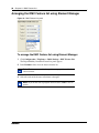
To configure a Network Device to be the IP Music source ..........................................290
BCM 4.0 Device Configuration Guide
6
Task List
N0060600
7
Contents
Chapter 1
Getting started with BCM . . . . . . . . . . . . . . . . . . . . . . . . . . . . . . . . . . . . . . . 15
About this guide . . . . . . . . . . . . . . . . . . . . . . . . . . . . . . . . . . . . . . . . . . . . . . . . . . . . . . 15
Purpose . . . . . . . . . . . . . . . . . . . . . . . . . . . . . . . . . . . . . . . . . . . . . . . . . . . . . . . . . 15
Audience . . . . . . . . . . . . . . . . . . . . . . . . . . . . . . . . . . . . . . . . . . . . . . . . . . . . . . . . 15
Acronyms . . . . . . . . . . . . . . . . . . . . . . . . . . . . . . . . . . . . . . . . . . . . . . . . . . . . . . . . . . . 16
Organization . . . . . . . . . . . . . . . . . . . . . . . . . . . . . . . . . . . . . . . . . . . . . . . . . . . . . 16
About BCM . . . . . . . . . . . . . . . . . . . . . . . . . . . . . . . . . . . . . . . . . . . . . . . . . . . . . . . . . 16
BCM key hardware elements . . . . . . . . . . . . . . . . . . . . . . . . . . . . . . . . . . . . . . . . 17
Symbols and conventions used in this guide . . . . . . . . . . . . . . . . . . . . . . . . . . . . . . . . 18
Related publications . . . . . . . . . . . . . . . . . . . . . . . . . . . . . . . . . . . . . . . . . . . . . . . . . . 19
How to get Help . . . . . . . . . . . . . . . . . . . . . . . . . . . . . . . . . . . . . . . . . . . . . . . . . . . . . . 21
Getting Help from the Nortel Web site . . . . . . . . . . . . . . . . . . . . . . . . . . . . . . . . . 21
Getting Help over the telephone from a Nortel Solutions Center . . . . . . . . . . . . . 22
Getting Help through a Nortel distributor or reseller . . . . . . . . . . . . . . . . . . . . . . . 22
Chapter 2
Welcome panel . . . . . . . . . . . . . . . . . . . . . . . . . . . . . . . . . . . . . . . . . . . . . . . . 23
Chapter 3
System Software . . . . . . . . . . . . . . . . . . . . . . . . . . . . . . . . . . . . . . . . . . . . . . 25
Setting Date and Time . . . . . . . . . . . . . . . . . . . . . . . . . . . . . . . . . . . . . . . . . . . . . . . . . 25
Setting clock control to local system . . . . . . . . . . . . . . . . . . . . . . . . . . . . . . . . . . . 28
Chapter 4
System schedule settings and services scheduling . . . . . . . . . . . . . . . . . 29
Configuring schedule names and timers . . . . . . . . . . . . . . . . . . . . . . . . . . . . . . . . . . . 30
Default time settings . . . . . . . . . . . . . . . . . . . . . . . . . . . . . . . . . . . . . . . . . . . . . . . 31
Configuring scheduled service . . . . . . . . . . . . . . . . . . . . . . . . . . . . . . . . . . . . . . . . . . 31
Chapter 5
System features and feature codes . . . . . . . . . . . . . . . . . . . . . . . . . . . . . . . 33
BCM feature codes . . . . . . . . . . . . . . . . . . . . . . . . . . . . . . . . . . . . . . . . . . . . . . . . . . . 33
Button programming features . . . . . . . . . . . . . . . . . . . . . . . . . . . . . . . . . . . . . . . . . . . 36
Chapter 6
DN records parameters . . . . . . . . . . . . . . . . . . . . . . . . . . . . . . . . . . . . . . . . . 41
Main panel tabs: common fields . . . . . . . . . . . . . . . . . . . . . . . . . . . . . . . . . . . . . . . . . 42
Line Access tab . . . . . . . . . . . . . . . . . . . . . . . . . . . . . . . . . . . . . . . . . . . . . . . . . . . . . . 44
Line Access - Properties tab . . . . . . . . . . . . . . . . . . . . . . . . . . . . . . . . . . . . . . . . . 44
BCM 4.0 Device Configuration Guide
8
Contents
Line Access - Line Assignment tab . . . . . . . . . . . . . . . . . . . . . . . . . . . . . . . . . . . . 46
Line Access - Line Pool Access tab . . . . . . . . . . . . . . . . . . . . . . . . . . . . . . . . . . . 48
Line Access - Answer DNs tab . . . . . . . . . . . . . . . . . . . . . . . . . . . . . . . . . . . . . . . 49
Capabilities and Preferences main tab . . . . . . . . . . . . . . . . . . . . . . . . . . . . . . . . . . . . 50
Capabilities and Preferences - Properties tab . . . . . . . . . . . . . . . . . . . . . . . . . . . . 51
Capabilities and Preferences - Capabilities tab . . . . . . . . . . . . . . . . . . . . . . . . . . 52
Capabilities and Preferences - SWCA Call Group tab . . . . . . . . . . . . . . . . . . . . . 55
Capabilities and Preferences - Preferences tab . . . . . . . . . . . . . . . . . . . . . . . . . . 56
Capabilities and Preferences - Button Programming table . . . . . . . . . . . . . . . . . . 58
Capabilities and Preferences - Button Programming tab . . . . . . . . . . . . . . . . . . . 58
Capabilities and Preferences - User Speed Dial tab . . . . . . . . . . . . . . . . . . . . . . . 61
Capabilities and Preferences - ATA Settings tab . . . . . . . . . . . . . . . . . . . . . . . . . 62
Capabilities and Preferences - IP Terminal Details tab . . . . . . . . . . . . . . . . . . . . . 64
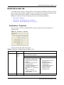
Restrictions main tab . . . . . . . . . . . . . . . . . . . . . . . . . . . . . . . . . . . . . . . . . . . . . . . . . . 65
Restrictions - Properties . . . . . . . . . . . . . . . . . . . . . . . . . . . . . . . . . . . . . . . . . . . . 65
Restrictions - Set Restrictions tab . . . . . . . . . . . . . . . . . . . . . . . . . . . . . . . . . . . . . 66
Restrictions - Line/Set Restrictions tab . . . . . . . . . . . . . . . . . . . . . . . . . . . . . . . . . 67
Chapter 7
Common procedures: copying and renumbering DNs . . . . . . . . . . . . . . . 69
Copying settings to other DNs . . . . . . . . . . . . . . . . . . . . . . . . . . . . . . . . . . . . . . . . . . . 69
Renumbering DNs . . . . . . . . . . . . . . . . . . . . . . . . . . . . . . . . . . . . . . . . . . . . . . . . . 70
Chapter 8
Global telephony settings . . . . . . . . . . . . . . . . . . . . . . . . . . . . . . . . . . . . . . . 71
Feature Settings . . . . . . . . . . . . . . . . . . . . . . . . . . . . . . . . . . . . . . . . . . . . . . . . . . . . . 72
Feature Settings panel . . . . . . . . . . . . . . . . . . . . . . . . . . . . . . . . . . . . . . . . . . . . . 73
Answer DN answer key levels . . . . . . . . . . . . . . . . . . . . . . . . . . . . . . . . . . . . . . . . 76
Timers . . . . . . . . . . . . . . . . . . . . . . . . . . . . . . . . . . . . . . . . . . . . . . . . . . . . . . . . . . 76
Advanced Feature Settings . . . . . . . . . . . . . . . . . . . . . . . . . . . . . . . . . . . . . . . . . . . . . 78
System Wide Call Appearances Control . . . . . . . . . . . . . . . . . . . . . . . . . . . . . . . . 78
ONN Blocking (North American systems) . . . . . . . . . . . . . . . . . . . . . . . . . . . . . . . 80
Silent Monitor . . . . . . . . . . . . . . . . . . . . . . . . . . . . . . . . . . . . . . . . . . . . . . . . . . . . 81
Reset logs . . . . . . . . . . . . . . . . . . . . . . . . . . . . . . . . . . . . . . . . . . . . . . . . . . . . . . . 82
Chapter 9
Telephony system and device programming . . . . . . . . . . . . . . . . . . . . . . . 83
Chapter 10
Configuring system speed dial numbers. . . . . . . . . . . . . . . . . . . . . . . . . . . 85
System Speed Dial panel . . . . . . . . . . . . . . . . . . . . . . . . . . . . . . . . . . . . . . . . . . . . . . 85
N0060600
Contents
9
Chapter 11
DMC Feature List . . . . . . . . . . . . . . . . . . . . . . . . . . . . . . . . . . . . . . . . . . . . . . 89
Arranging the DMC Feature list using Element Manager . . . . . . . . . . . . . . . . . . . . . . 90
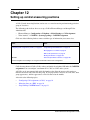
Chapter 12
Setting up central answering positions . . . . . . . . . . . . . . . . . . . . . . . . . . . . 91
Configuring CAP assignments (eCAPs) . . . . . . . . . . . . . . . . . . . . . . . . . . . . . . . . . . . 92
Programming CAP/KIM buttons . . . . . . . . . . . . . . . . . . . . . . . . . . . . . . . . . . . . . . . . . 93
Managing lines on a KIM . . . . . . . . . . . . . . . . . . . . . . . . . . . . . . . . . . . . . . . . . . . . . . . 94
Chapter 13
Creating ring groups . . . . . . . . . . . . . . . . . . . . . . . . . . . . . . . . . . . . . . . . . . . 95
Ring Groups - Members . . . . . . . . . . . . . . . . . . . . . . . . . . . . . . . . . . . . . . . . . . . . . . . 96
Ring Groups - Line Settings tab . . . . . . . . . . . . . . . . . . . . . . . . . . . . . . . . . . . . . . . . . 97
Chapter 14
Configuring Hunt Groups . . . . . . . . . . . . . . . . . . . . . . . . . . . . . . . . . . . . . . . 99
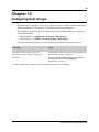
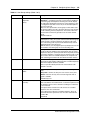
Hunt Groups system setup . . . . . . . . . . . . . . . . . . . . . . . . . . . . . . . . . . . . . . . . . . . . 100
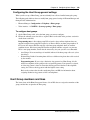
Configuring the Hunt Group general settings . . . . . . . . . . . . . . . . . . . . . . . . . . . 103
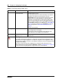
Hunt Group members and lines . . . . . . . . . . . . . . . . . . . . . . . . . . . . . . . . . . . . . . . . . 103
Chapter 15
Monitoring Hunt Groups . . . . . . . . . . . . . . . . . . . . . . . . . . . . . . . . . . . . . . . 107
Monitoring external hunt group calls . . . . . . . . . . . . . . . . . . . . . . . . . . . . . . . . . . . . . 107
Chapter 16
Configuring Hospitality services . . . . . . . . . . . . . . . . . . . . . . . . . . . . . . . . 109
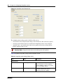
Hospitality - General . . . . . . . . . . . . . . . . . . . . . . . . . . . . . . . . . . . . . . . . . . . . . . . . . 109
Hospitality - Rooms . . . . . . . . . . . . . . . . . . . . . . . . . . . . . . . . . . . . . . . . . . . . . . . . . . 111
Setting up your hospitality system . . . . . . . . . . . . . . . . . . . . . . . . . . . . . . . . . . . . . . . 112
Chapter 17
Configuring analog telephones and devices. . . . . . . . . . . . . . . . . . . . . . . 115
Configuring an analog telephone . . . . . . . . . . . . . . . . . . . . . . . . . . . . . . . . . . . . . . . . 116
Chapter 18
Configuring telephones: Digital telephones . . . . . . . . . . . . . . . . . . . . . . . 119
Using the DN panels . . . . . . . . . . . . . . . . . . . . . . . . . . . . . . . . . . . . . . . . . . . . . . . . . 120
System DNs - Line Access tab . . . . . . . . . . . . . . . . . . . . . . . . . . . . . . . . . . . . . . . . . 121
Job aid: Notes about assigning lines to telephones . . . . . . . . . . . . . . . . . . . . . . 121
Line Assignment and Line Pools . . . . . . . . . . . . . . . . . . . . . . . . . . . . . . . . . . . . . . . . 124
Job aid: Answer DN notes . . . . . . . . . . . . . . . . . . . . . . . . . . . . . . . . . . . . . . . . . . 124
Configuring Capabilities and Preferences . . . . . . . . . . . . . . . . . . . . . . . . . . . . . . . . . 125
Job aid: Assigning intercom (I/C) buttons (keys) . . . . . . . . . . . . . . . . . . . . . . . . . 126
BCM 4.0 Device Configuration Guide
10
Contents
Configuring telephone capabilities . . . . . . . . . . . . . . . . . . . . . . . . . . . . . . . . . . . . . . . 126
Job aid: Line redirection notes . . . . . . . . . . . . . . . . . . . . . . . . . . . . . . . . . . . . . . 128
Configuring Preferences . . . . . . . . . . . . . . . . . . . . . . . . . . . . . . . . . . . . . . . . . . . . . . 129
Job aid: Call log notes . . . . . . . . . . . . . . . . . . . . . . . . . . . . . . . . . . . . . . . . . . . . . 130
Telephone memory button programming . . . . . . . . . . . . . . . . . . . . . . . . . . . . . . . . . 131
Job aid: Notes about button programming . . . . . . . . . . . . . . . . . . . . . . . . . . . . . 131
User speed dials . . . . . . . . . . . . . . . . . . . . . . . . . . . . . . . . . . . . . . . . . . . . . . . . . . . . 132
Outgoing call restrictions . . . . . . . . . . . . . . . . . . . . . . . . . . . . . . . . . . . . . . . . . . . . . . 132
Chapter 19
Configuring telephones: IP telephones . . . . . . . . . . . . . . . . . . . . . . . . . . . 135
Configuring an IP telephone . . . . . . . . . . . . . . . . . . . . . . . . . . . . . . . . . . . . . . . . . . . 136
PVQM - Proactive Voice Quality Monitoring . . . . . . . . . . . . . . . . . . . . . . . . . . . . . . . 137
Chapter 20
Global VoIP features . . . . . . . . . . . . . . . . . . . . . . . . . . . . . . . . . . . . . . . . . . 139
IP feature list . . . . . . . . . . . . . . . . . . . . . . . . . . . . . . . . . . . . . . . . . . . . . . . . . . . . . . . 139
IP telephone feature display labels . . . . . . . . . . . . . . . . . . . . . . . . . . . . . . . . . . . . . . 141
Hot desking IP telephone configurations . . . . . . . . . . . . . . . . . . . . . . . . . . . . . . . . . . 143
Using the Hot desking feature . . . . . . . . . . . . . . . . . . . . . . . . . . . . . . . . . . . . . . . 144
Configuring a new time zone on a remote IP telephone . . . . . . . . . . . . . . . . . . . . . . 146
Download firmware to a Nortel IP telephone . . . . . . . . . . . . . . . . . . . . . . . . . . . . . . . 147
Chapter 21
Default memory button programming for telephones . . . . . . . . . . . . . . . 149
Rules of default button assignment . . . . . . . . . . . . . . . . . . . . . . . . . . . . . . . . . . . . . . 149
7316E digital phone button defaults . . . . . . . . . . . . . . . . . . . . . . . . . . . . . . . . . . . . . 150
7316 digital phone button defaults . . . . . . . . . . . . . . . . . . . . . . . . . . . . . . . . . . . . . . . 152
7208 digital phone button defaults . . . . . . . . . . . . . . . . . . . . . . . . . . . . . . . . . . . . . . . 153
7100 digital phone button defaults . . . . . . . . . . . . . . . . . . . . . . . . . . . . . . . . . . . . . . . 154
7000 digital phone button defaults . . . . . . . . . . . . . . . . . . . . . . . . . . . . . . . . . . . . . . . 154
7406 digital phone button defaults . . . . . . . . . . . . . . . . . . . . . . . . . . . . . . . . . . . . . . . 155
IP telephone button defaults . . . . . . . . . . . . . . . . . . . . . . . . . . . . . . . . . . . . . . . . . . . 155
IP telephone 2007 button defaults . . . . . . . . . . . . . . . . . . . . . . . . . . . . . . . . . . . 158
IP audio conference phone 2033 button defaults . . . . . . . . . . . . . . . . . . . . . . . . 162
IP Phone 1120E and IP Phone 1140E . . . . . . . . . . . . . . . . . . . . . . . . . . . . . . . . 166
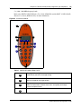
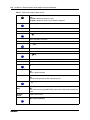
WLAN handset 2210/2211/2212 button defaults . . . . . . . . . . . . . . . . . . . . . . . . 171
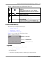
WLAN handset display . . . . . . . . . . . . . . . . . . . . . . . . . . . . . . . . . . . . . . . . . . . . . . . 173
Status area . . . . . . . . . . . . . . . . . . . . . . . . . . . . . . . . . . . . . . . . . . . . . . . . . . . . . 173
Information area . . . . . . . . . . . . . . . . . . . . . . . . . . . . . . . . . . . . . . . . . . . . . . . . . 174
Feature options area . . . . . . . . . . . . . . . . . . . . . . . . . . . . . . . . . . . . . . . . . . . . . . 174
DMC Portables (413X/414X) (Europe only) . . . . . . . . . . . . . . . . . . . . . . . . . . . . 174
N0060600
Contents
11
Chapter 22
Programming telephone sets: Desktop Assistant portfolio . . . . . . . . . . 179
Introduction to Desktop Assistant Pro — Administrator Edition . . . . . . . . . . . . . . . . . 183
Desktop Assistant Pro — Administrator Edition main window . . . . . . . . . . . . . . . . . . 183
Menu bar commands . . . . . . . . . . . . . . . . . . . . . . . . . . . . . . . . . . . . . . . . . . . . . 184
Button programming . . . . . . . . . . . . . . . . . . . . . . . . . . . . . . . . . . . . . . . . . . . . . . 186
Button labeling . . . . . . . . . . . . . . . . . . . . . . . . . . . . . . . . . . . . . . . . . . . . . . . . . . 186
Chapter 23
Telephony features . . . . . . . . . . . . . . . . . . . . . . . . . . . . . . . . . . . . . . . . . . . 187
Features to set up telephone set features . . . . . . . . . . . . . . . . . . . . . . . . . . . . . . . . . 187
Moving line buttons . . . . . . . . . . . . . . . . . . . . . . . . . . . . . . . . . . . . . . . . . . . . . . . 189
Receiver volume . . . . . . . . . . . . . . . . . . . . . . . . . . . . . . . . . . . . . . . . . . . . . . . . . 189
Programming distinctive ringing . . . . . . . . . . . . . . . . . . . . . . . . . . . . . . . . . . . . . 190
Ring volume . . . . . . . . . . . . . . . . . . . . . . . . . . . . . . . . . . . . . . . . . . . . . . . . . . . . 190
Auxiliary ringer . . . . . . . . . . . . . . . . . . . . . . . . . . . . . . . . . . . . . . . . . . . . . . . . . . . . . . 190
Chapter 24
Feature configuration: Answering calls. . . . . . . . . . . . . . . . . . . . . . . . . . . 193
Answering calls directed to your telephone . . . . . . . . . . . . . . . . . . . . . . . . . . . . . . . . 193
Configuring handsfree and handsfree answerback . . . . . . . . . . . . . . . . . . . . . . . 193
Answering calls not directed to your telephone . . . . . . . . . . . . . . . . . . . . . . . . . . . . . 194
Call Queuing . . . . . . . . . . . . . . . . . . . . . . . . . . . . . . . . . . . . . . . . . . . . . . . . . . . . 194
Directed Pickup . . . . . . . . . . . . . . . . . . . . . . . . . . . . . . . . . . . . . . . . . . . . . . . . . . 194
Pickup Group . . . . . . . . . . . . . . . . . . . . . . . . . . . . . . . . . . . . . . . . . . . . . . . . . . . 195
Answer DNs . . . . . . . . . . . . . . . . . . . . . . . . . . . . . . . . . . . . . . . . . . . . . . . . . . . . 196
Configuring privacy . . . . . . . . . . . . . . . . . . . . . . . . . . . . . . . . . . . . . . . . . . . . . . . . . . 197
Do Not Disturb . . . . . . . . . . . . . . . . . . . . . . . . . . . . . . . . . . . . . . . . . . . . . . . . . . . 197
DND on Busy . . . . . . . . . . . . . . . . . . . . . . . . . . . . . . . . . . . . . . . . . . . . . . . . . . . 197
Turn Privacy on or off . . . . . . . . . . . . . . . . . . . . . . . . . . . . . . . . . . . . . . . . . . . . . 198
Intrusion controls . . . . . . . . . . . . . . . . . . . . . . . . . . . . . . . . . . . . . . . . . . . . . . . . . 200
Holding calls . . . . . . . . . . . . . . . . . . . . . . . . . . . . . . . . . . . . . . . . . . . . . . . . . . . . . . . 200
Using Hold . . . . . . . . . . . . . . . . . . . . . . . . . . . . . . . . . . . . . . . . . . . . . . . . . . . . . . 200
Hold automatically (autohold) . . . . . . . . . . . . . . . . . . . . . . . . . . . . . . . . . . . . . . . 201
Hold a call exclusively . . . . . . . . . . . . . . . . . . . . . . . . . . . . . . . . . . . . . . . . . . . . . 201
Parking or transferring calls . . . . . . . . . . . . . . . . . . . . . . . . . . . . . . . . . . . . . . . . . . . . 201
Transfer (answered) calls . . . . . . . . . . . . . . . . . . . . . . . . . . . . . . . . . . . . . . . . . . 202
Transfer (unanswered) calls . . . . . . . . . . . . . . . . . . . . . . . . . . . . . . . . . . . . . . . . 202
Line redirection . . . . . . . . . . . . . . . . . . . . . . . . . . . . . . . . . . . . . . . . . . . . . . . . . . 203
Call forward (unanswered) calls . . . . . . . . . . . . . . . . . . . . . . . . . . . . . . . . . . . . . 204
Call Forward and voice mail . . . . . . . . . . . . . . . . . . . . . . . . . . . . . . . . . . . . . . . . 205
Camp-on . . . . . . . . . . . . . . . . . . . . . . . . . . . . . . . . . . . . . . . . . . . . . . . . . . . . . . . 205
BCM 4.0 Device Configuration Guide
12
Contents
Call Park . . . . . . . . . . . . . . . . . . . . . . . . . . . . . . . . . . . . . . . . . . . . . . . . . . . . . . . 206
Callback . . . . . . . . . . . . . . . . . . . . . . . . . . . . . . . . . . . . . . . . . . . . . . . . . . . . . . . 207
Sharing calls by parking on SWCA buttons . . . . . . . . . . . . . . . . . . . . . . . . . . . . 207
Call information . . . . . . . . . . . . . . . . . . . . . . . . . . . . . . . . . . . . . . . . . . . . . . . . . . . . . 209
Call display information . . . . . . . . . . . . . . . . . . . . . . . . . . . . . . . . . . . . . . . . . . . . 209
Call duration timer . . . . . . . . . . . . . . . . . . . . . . . . . . . . . . . . . . . . . . . . . . . . . . . . 209
Time and date display . . . . . . . . . . . . . . . . . . . . . . . . . . . . . . . . . . . . . . . . . . . . . 209
Malicious Caller ID (MCID) . . . . . . . . . . . . . . . . . . . . . . . . . . . . . . . . . . . . . . . . . 210
Call log . . . . . . . . . . . . . . . . . . . . . . . . . . . . . . . . . . . . . . . . . . . . . . . . . . . . . . . . 210
LogIt . . . . . . . . . . . . . . . . . . . . . . . . . . . . . . . . . . . . . . . . . . . . . . . . . . . . . . . . . . 212
Chapter 25
Feature configuration: Making calls. . . . . . . . . . . . . . . . . . . . . . . . . . . . . . 213
Blocking user access to feature programming . . . . . . . . . . . . . . . . . . . . . . . . . . . . . 213
Protecting outgoing call privacy . . . . . . . . . . . . . . . . . . . . . . . . . . . . . . . . . . . . . . . . . 213
Managing a busy signal on an internal call . . . . . . . . . . . . . . . . . . . . . . . . . . . . . . . . 214
Priority Call . . . . . . . . . . . . . . . . . . . . . . . . . . . . . . . . . . . . . . . . . . . . . . . . . . . . . 214
Ring Again . . . . . . . . . . . . . . . . . . . . . . . . . . . . . . . . . . . . . . . . . . . . . . . . . . . . . . 214
Other ways of communicating with internal users . . . . . . . . . . . . . . . . . . . . . . . . . . . 214
Leaving a message . . . . . . . . . . . . . . . . . . . . . . . . . . . . . . . . . . . . . . . . . . . . . . . 215
Paging . . . . . . . . . . . . . . . . . . . . . . . . . . . . . . . . . . . . . . . . . . . . . . . . . . . . . . . . . 215
Making announcements to individuals (Voice Call) . . . . . . . . . . . . . . . . . . . . . . . 217
Create a conference call . . . . . . . . . . . . . . . . . . . . . . . . . . . . . . . . . . . . . . . . . . . 218
Dialing shortcuts . . . . . . . . . . . . . . . . . . . . . . . . . . . . . . . . . . . . . . . . . . . . . . . . . . . . 220
Last Number Redial . . . . . . . . . . . . . . . . . . . . . . . . . . . . . . . . . . . . . . . . . . . . . . 220
Saved Number Redial . . . . . . . . . . . . . . . . . . . . . . . . . . . . . . . . . . . . . . . . . . . . . 221
Autodial . . . . . . . . . . . . . . . . . . . . . . . . . . . . . . . . . . . . . . . . . . . . . . . . . . . . . . . . 221
Speed dialing . . . . . . . . . . . . . . . . . . . . . . . . . . . . . . . . . . . . . . . . . . . . . . . . . . . 221
Programming memory buttons . . . . . . . . . . . . . . . . . . . . . . . . . . . . . . . . . . . . . . 222
Chapter 26
Using telephones for special features . . . . . . . . . . . . . . . . . . . . . . . . . . . . 225
Special feature telephones . . . . . . . . . . . . . . . . . . . . . . . . . . . . . . . . . . . . . . . . . . . . 225
Supervisor telephone for silent monitoring . . . . . . . . . . . . . . . . . . . . . . . . . . . . . 227
Hospitality services telephones . . . . . . . . . . . . . . . . . . . . . . . . . . . . . . . . . . . . . . 227
Setting up a central answering position . . . . . . . . . . . . . . . . . . . . . . . . . . . . . . . . . . . 227
Prime line . . . . . . . . . . . . . . . . . . . . . . . . . . . . . . . . . . . . . . . . . . . . . . . . . . . . . . 228
Direct dial telephone . . . . . . . . . . . . . . . . . . . . . . . . . . . . . . . . . . . . . . . . . . . . . . 229
Creating an enhanced CAP station . . . . . . . . . . . . . . . . . . . . . . . . . . . . . . . . . . . 229
Hunt groups . . . . . . . . . . . . . . . . . . . . . . . . . . . . . . . . . . . . . . . . . . . . . . . . . . . . . 230
Ringing groups . . . . . . . . . . . . . . . . . . . . . . . . . . . . . . . . . . . . . . . . . . . . . . . . . . 230
N0060600
Contents
13
Chapter 27
Display prompts and messages . . . . . . . . . . . . . . . . . . . . . . . . . . . . . . . . . 233
Common display prompts . . . . . . . . . . . . . . . . . . . . . . . . . . . . . . . . . . . . . . . . . . . . . 233
Viewing active services . . . . . . . . . . . . . . . . . . . . . . . . . . . . . . . . . . . . . . . . . . . . 244
Call log prompts . . . . . . . . . . . . . . . . . . . . . . . . . . . . . . . . . . . . . . . . . . . . . . . . . . . . . 245
Report and record alarm codes . . . . . . . . . . . . . . . . . . . . . . . . . . . . . . . . . . . . . . . . . 247
Chapter 28
About System-Wide Call Appearance (SWCA) keys. . . . . . . . . . . . . . . . . 249
Managing calls using SWCA keys . . . . . . . . . . . . . . . . . . . . . . . . . . . . . . . . . . . . . . . 250
Other features that affect how you use SWCA . . . . . . . . . . . . . . . . . . . . . . . . . . . . . 252
Chapter 29
Market profile attributes . . . . . . . . . . . . . . . . . . . . . . . . . . . . . . . . . . . . . . . 255
Media bay module availability . . . . . . . . . . . . . . . . . . . . . . . . . . . . . . . . . . . . . . . . . . 255
FEM MBM–Norstar trunk cartridge combinations . . . . . . . . . . . . . . . . . . . . . . . . . . . 256
Time zones and language information . . . . . . . . . . . . . . . . . . . . . . . . . . . . . . . . . . . 257
Time and date format based on language . . . . . . . . . . . . . . . . . . . . . . . . . . . . . 257
Language support for South America and Central America . . . . . . . . . . . . . . . . 258
Caller ID display formats . . . . . . . . . . . . . . . . . . . . . . . . . . . . . . . . . . . . . . . . . . . 259
Core parameters for market profiles . . . . . . . . . . . . . . . . . . . . . . . . . . . . . . . . . . . . . 259
Global analog trunk parameters . . . . . . . . . . . . . . . . . . . . . . . . . . . . . . . . . . . . . . . . 272
GASM8 parameters . . . . . . . . . . . . . . . . . . . . . . . . . . . . . . . . . . . . . . . . . . . . . . . . . . 275
ISDN line services . . . . . . . . . . . . . . . . . . . . . . . . . . . . . . . . . . . . . . . . . . . . . . . . . . . 278
Analog and digital trunk types . . . . . . . . . . . . . . . . . . . . . . . . . . . . . . . . . . . . . . . . . . 279
Chapter 30
Configuring the music source . . . . . . . . . . . . . . . . . . . . . . . . . . . . . . . . . . 281
Selecting the music source . . . . . . . . . . . . . . . . . . . . . . . . . . . . . . . . . . . . . . . . . . . . 282
Configuring Music Manager . . . . . . . . . . . . . . . . . . . . . . . . . . . . . . . . . . . . . . . . . . . . 285
Opening the Music Manager Administration application . . . . . . . . . . . . . . . . . . . 285
Loading music onto the BCM . . . . . . . . . . . . . . . . . . . . . . . . . . . . . . . . . . . . . . . 286
Deleting music from BCM . . . . . . . . . . . . . . . . . . . . . . . . . . . . . . . . . . . . . . . . . . 287
Adding music to the Play List . . . . . . . . . . . . . . . . . . . . . . . . . . . . . . . . . . . . . . . 287
Removing music from the Play List . . . . . . . . . . . . . . . . . . . . . . . . . . . . . . . . . . . 287
Using the BcmAmp Player . . . . . . . . . . . . . . . . . . . . . . . . . . . . . . . . . . . . . . . . . 289
Configuring a Network Device to be the IP Music Source . . . . . . . . . . . . . . . . . . . . . 290
Index . . . . . . . . . . . . . . . . . . . . . . . . . . . . . . . . . . . . . . . . . . . . . . . . . . . . . . . 293
BCM 4.0 Device Configuration Guide
14
Contents
N0060600
15
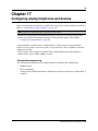
Chapter 1
Getting started with BCM
Refer to the following topics for general BCM information:
•
•
•
•
“About BCM”
“Symbols and conventions used in this guide” on page 18
“Related publications” on page 19
“How to get Help” on page 21
About this guide
The BCM 4.0 Device Configuration Guide describes how to configure and assign features to
telephony devices through Telset and through Element Manager.
Purpose
The concepts, operations, and tasks described in this guide relate to the BCM software. This guide
provides task-based information about how to assign features and provide basic programming for
the Business Communications Manager.
Use Element Manager, Startup Profile, and Telset Administration to configure various BCM
parameters.
In brief, the information in this guide explains:
•
•
•
global telephony settings
steps to configure DNs
product features and how to assign them
Audience
The BCM 4.0 Device Configuration Guide is directed to installers who install, configure, and
maintain BCM systems.
To use this guide, you must:
•
•
•
be an authorized BCM installer or administrator within your organization
know basic Nortel BCM terminology
be knowledgeable about telephony and IP networking technology
BCM 4.0 Device Configuration Guide
16
Chapter 1 Getting started with BCM
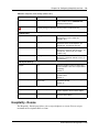
Acronyms
The following is a list of acronyms used in this guide.
Table 1 Acronyms
Acronym
Description
ASM
Analog station module
ATA
analog terminal adapter
BRI
Basic Rate Interface
BCM
Business Communications Manager
CAP
Central Answering Position
CC
Contact Center
CLID
Calling Line Identification
CoS
Class of Service
DPNSS
Digital Private Network Signaling System
ISDN
Integrated Services Digital Network
KIM
Key Indicator Module
MCDN
Meridian Customer Defined Networking
MCID
malicious call identification
MWI
message wait indicator
OLI
outgoing line identification
ONN
outgoing name and number
PVQM
proactive voice quality monitoring
SM
silent monitor
SWCA
system-wide call appearance
Organization
This guide is organized for easy access to information that explains the concepts, operations, and
procedures associated with the BCM system.
About BCM
The BCM system provides private network and telephony management capability to small and
medium-sized businesses.
The BCM system:
•
•
N0060600
integrates voice and data capabilities, VoIP gateway functions, and QoS data-routing features
into a single telephony system
enables you to create and provide telephony applications for use in a business environment
Chapter 1 Getting started with BCM
17
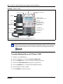
BCM key hardware elements
BCM includes the following key elements:
•
•
•
•
•
•
BCM200 main unit
BCM400 main unit
BCM1000 main unit
BCM expansion unit (compatible with BCM400 main unit)
BCM400 expansion gateway
BCM media bay modules (MBM):
— 4x16
— ASM8, ASM8+
— BRIM
— CTM4, CTM8
— DDIM
— DSM16+, DSM32+
— DTM
— FEM
— GASM
— GATM4, GATM8
BCM features
BCM supports the complete range of IP telephony features offered by existing BCM products:
Note: You enable the following features by entering the appropriate keycodes (no
additional hardware is required).
•
•
VoIP Gateway: Up to 12 VoIP trunks
VoIP Telephony Clients: Up to 64 VoIP Telephony clients, supporting the range of Nortel
IP Phones.
BCM applications
BCM supports many applications provided on the existing BCM platforms.
Note: You enable the following features by entering the appropriate keycodes (no
additional hardware is required).
•
•
•
Voice Messaging for standard voice mail and auto-attendant features
Unified Messaging providing integrated voice mail management between voice mail and
common e-mail applications
Fax Suite providing support for attached analog fax devices
BCM 4.0 Device Configuration Guide
18
Chapter 1 Getting started with BCM
•
•
•
•
•
•
Voice Networking features
LAN CTE (computer telephony engine)
VEWAN (Voice Enabled WAN)
IVR (Integrated Voice Response)
IP Music
Intelligent Contact Center
Symbols and conventions used in this guide
These symbols are used to highlight critical information for the BCM system:
Caution: Alerts you to conditions where you can damage the equipment.
Danger: Alerts you to conditions where you can get an electrical shock.
Warning: Alerts you to conditions where you can cause the system to fail or work
improperly.
Note: Alerts you to important information.
Tip: Alerts you to additional information that can help you perform a task.
!
Security Note: Indicates a point of system security where a default should be
changed, or where the administrator needs to make a decision about the level of
security required for the system.
Warning: Alerts you to ground yourself with an antistatic grounding strap
before performing the maintenance procedure.
N0060600
Chapter 1 Getting started with BCM
19
Warning: Alerts you to remove the BCM main unit and expansion unit power
cords from the ac outlet before performing any maintenance procedure.
The following conventions and symbols are used to represent the Business Series Terminal display
and dialpad.
Convention
Example
Used for
Word in a special font (shown in
the top line of the display)
Pswd:
Command line prompts on display telephones.
Underlined word in capital letters
(shown in the bottom line of a
two-line display telephone)
PLAY
Display option. Available on two line display
telephones. Press the button directly below the
option on the display to proceed.
Dialpad buttons
£
Buttons you press on the dialpad to select a
particular option.
The following text conventions are used in this guide to indicate the information described:
Convention
Description
bold Courier
text
Indicates command names and options and text that you must enter.
Example: Use the info command.
Example: Enter show ip {alerts|routes}.
italic text
Indicates book titles.
plain Courier
text
Indicates command syntax and system output (for example, prompts
and system messages).
Example: Set Trap Monitor Filters
FEATURE
HOLD
RELEASE
Indicates that you press the button with the coordinating icon on
whichever set you are using.
Related publications
This section provides a list of additional documents referred to in this guide. There are two types
of publications: Technical Documents on page 19 and User Guides on page 20.
Technical Documents
BCM 4.0 System Overview (N0060607)
BCM 4.0 Device Configuration Guide
20
Chapter 1 Getting started with BCM
System Installation
BCM 4.0 for BCM1000 Installation and Maintenance Guide Addendum (N0060603)
BCM200/400 BCM 4.0 Installation and Maintenance Guide (N0060612)
Keycode Installation Guide (N0060625)
System Programming
BCM 4.0 Administration Guide (N0060598)
BCM 4.0 Networking Configuration Guide (N0060606)
BCM 4.0 Telset Administration Guide (N0060610)
Telephones and Peripherals
BCM 4.0 Telephony Device Installation Guide (N0060609)
BST Doorphone Installation and Configuration Guide (P1013654)
T24 KIM Installation Card (P0603481)
IP Key Expansion Module (KEM) User Guide
Digital Mobility
DECT Deployment and Demonstration Tool
Digital Mobility System Installation and Configuration Guide (N0000623)
T7406 Cordless Handset Installation Guide (P0606142)
IP Telephony
i2050 Software Phone Installation Guide (N0022555)
IP Phone 1120E User Guide (NN-10300-062)
IP Phone 1140E User Guide (NN-10300-064)
IP Audio Conference Phone 2033 User Guide (N0060623)
WLAN IP Telephony Installation and Configuration Guide (N0060634)
User Guides
Telephones and Peripherals
BCM 4.0 Telephone Features User Guide (N0060608)
BST Doorphone User Guide (P0605668)
Central Answering Position (CAP) User Guide (P0603480)
Hospitality Features Card (N0027326)
N0060600
Chapter 1 Getting started with BCM
21
System-wide Call Appearance (SWCA) Features Card (N0027186)
T7000 Telephone User Card (P0912061)
T7100 Telephone User Card (P0609621)
T7208 Telephone User Card (P0609622)
T7316 Telephone User Card (P0935248)
T7316E Telephone User Card (P0609623)
Digital Mobility
DECT 413X/414X Handset User Guide (N0028550)
Digital Mobility Phone 7420 User Guide (N0000635)
Digital Mobility Phone 7430/7440 User Guide (N0028550)
T7406 Cordless Telephone User Card (P0942259)
IP Telephony
IP Audio Conference Phone 2033 User Guide (N0060623)
IP Phone 2001 User Guide (N0027313)
IP Phone 2002 User Guide (N0027300)
IP Phone 2004 User Guide (N0027284)
IP Phone 2007 User Guide (N0064498)
BCM WLAN 2210/2211/2212 Handset User Guide (N0009103)
How to get Help
This section explains how to get help for Nortel products and services.
Getting Help from the Nortel Web site
The best source of support for Nortel products is the Nortel Support Web site:
http://www.nortel.com/support
This site enables customers to:
•
•
•
•
•
download software and related tools
download technical documents, release notes, and product bulletins
sign up for automatic notification of new software and documentation
search the Support Web site and Nortel Knowledge Base
open and manage technical support cases
BCM 4.0 Device Configuration Guide
22
Chapter 1 Getting started with BCM
Getting Help over the telephone from a Nortel Solutions Center
If you have a Nortel support contract and cannot find the information you require on the
Nortel Support Web site, you can get help over the telephone from a Nortel Solutions Center.
In North America, call 1-800-4NORTEL (1-800-466-7835).
Outside North America, go to the Web site below and look up the telephone number that applies
in your region:
http://www.nortel.com/callus
When you speak to the telephone agent, you can reference an Express Routing Code (ERC) to
more quickly route your call to the appropriate support specialist. To locate the ERC for your
product or service, go to:
http://www.nortel.com/erc
Getting Help through a Nortel distributor or reseller
If you purchased a service contract for your Nortel product from a distributor or authorized
reseller, you can contact the technical support staff for that distributor or reseller.
N0060600
23
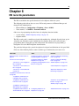
Chapter 2
Welcome panel
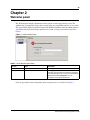
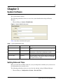
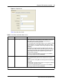
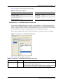
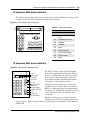
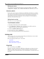
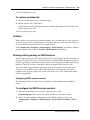
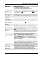
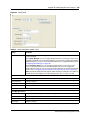
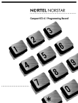
The Welcome panel displays information for the current account logged on the system. The
administrator is prompted to change the password before any programming menus are accessible.
This panel will be displayed on the first login to the BCM by nnadmin, when the administrator has
selected the forced password change option on an account, or if the password has expired. See
Figure 1.
Figure 1 Initial welcome panel
Table 2 Initial Welcome panel fields
Attribute
Value
Description
User ID
<read-only>
User ID you used to log on to the system.
Password
<alphanumeric>
To change password, select the field and enter new
password. The password must satisfy the password
policy requirements for the system. See the BCM 4.0
Administration Guide (N0060598) for more
information on password requirements.
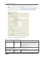
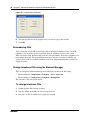
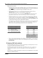
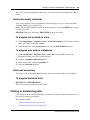
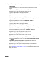
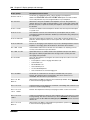
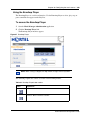
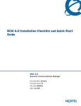
Once the password has been changed the entire navigation tree is accessible. See Figure 2.
BCM 4.0 Device Configuration Guide
24
Chapter 2 Welcome panel
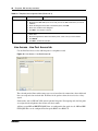
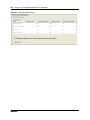
Figure 2 Welcome panel
Table 3 Welcome panel fields
Attribute
Value
Description
Account Notifications
<read-only>
Displays BCM administrative messages or notifications
regarding the current user.
User ID
<read-only>
User ID you used to log on to the system.
Telset User ID
<read-only>
User ID used to logon to the telset configuration interfaces for
telephony and CallPilot applications.
Last successful login
<read-only>
Date and time that this user account was last logged in the
system.
Current Account
N0060600
25
Chapter 3
System Software
The system software identity.
The following path indicates where to access the system identification settings in Element
Manager:
•
Element Manager: System > Identification
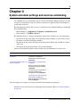
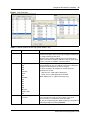
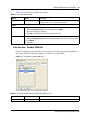
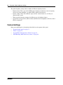
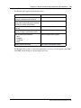
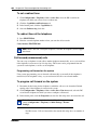
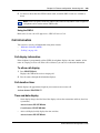
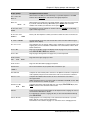
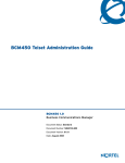
Figure 3 System Identification panel
Table 1 describes each field on this panel.
Table 1 System Identification fields
Attribute
Value
Description
Model
<read-only>
This is the system hardware release currently running on this
device.
System name
<alphanumeric>
It is easier to manage a group of systems if each system is
provided with a unique name or identification number.
Version
<read-only>
The version of software running on the BCM Main Unit.
Country or region
<read-only>
This setting defines internal system settings for default values,
available languages, and hardware and functional availability
for a specific country or region.
Setting Date and Time
How you set the Date and Time feature for your system depends on whether your system receives
this information from a network server.
The following path indicates where to access the date and time settings in Element Manager:
•
Element Manager: Configuration > System > Date and Time
BCM 4.0 Device Configuration Guide
26
Chapter 3 System Software
Click one of the following links to connect with the type of information you want to view:
Panel
Task
“Setting clock control to local system” on page 28
Click the navigation tree heading to access general information about Date and Time management.
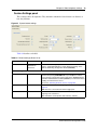
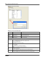
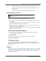
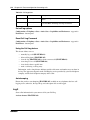
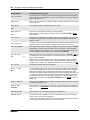
Figure 4 Date and time panel
Table 2 describes each field on the Date and Time panel.
Table 2 Date and Time panel fields (Sheet 1 of 2)
Attribute
Value
Description
Date and Time Source
NTP
Trunk
Manual
Set to NTP (Network Time Protocol) if the system uses a
network server to determine the correct time and date.
Set to Trunk to use time and date settings from a CO through
an analog or ISDN line.
Set to Manual if you want to be able to manually configure the
time and date for your system.
Network Time Protocol Settings
(Settings are active only if Clock Control Type is set to Network Time Protocol.)
NTP server address
N0060600
<IP address>
The IP address of the server that controls the network time and
date.
Chapter 3 System Software
27
Table 2 Date and Time panel fields (Sheet 2 of 2)
Attribute
Value
Description
Synch every (s)
NA (not applicable)
1-XXXX
The number of seconds specified to elapse between contacts
with the NTP server.
NA: Appears if you chose Manually in the Synch with Server
field.
1-XXXX: Number of seconds between contacts with the NTP
server.
NTP security mode
Secured
Unsecured
Select whether the NTP security mode is secured or
unsecured.
Raise Alarm if Clock differs
by at least (s)
<seconds>
The number of discrepancy seconds specified that must occur
before the system notifies you of a time difference from the
NTP server, if the system automatically checks with the NTP
server.
NTP key ID
<1-65,534>
ID for accessing the NTP.
NTP key string
<8 characters>
Control key corresponding to ID for accessing the NTP.
Date and time
<country/
region-specific date
and time format>
The current date and time.
Year
<numeric>
The current year in yyyy format.
Time zone
<drop-down list>
The appropriate time zone for the location of this system. The
Time zone must be set for software updates to be applied.
Daylight Savings Time
<read-only>
The appropriate mode for the Time zone.
Selected: The system automatically updates the time twice a
year.
Cleared: The system never updates the time for Daylight
Savings Time.
Current Date and Time
Note: North American Daylight Savings Time rules change in 2007.
Four time zones have been added to support regions that do not want to
switch to the new time zone rules. The time zones are identified
“pre-2007 DST”.
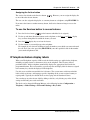
If the system is to synchronize with an NTP Server or trunk, check the following:
1
Set Date and Time Source to NTP or Trunk.
2
In the NTP server address field enter the IP address of the NTP server.
3
Set the number of seconds between synchronizations in normal operations (Synch Every).
BCM 4.0 Device Configuration Guide
28
Chapter 3 System Software
4
In the bottom frame, ensure that the Time zone is correct for the location of the local system.
5
If Trunk was selected in the Date and Time Source drop-down list, enter the year in the Year
field.
Note: Only time and date info are updated when NTP and Trunk
settings are selected. Year information is not updated. You also have full
control over time and date settings using telset admin even if NTP or
Trunk are selected. Any setting applied through telset admin are
over-written by the external source if NTP or Trunk are selected. Time
zones need to be set for software updates to be applied.
Setting clock control to local system
If you want the clock to be controlled locally:
1
Ensure that Clock Control Type is set to local.
2
In the bottom frame:
•
•
•
•
N0060600
In the Time Zone field, select the Time zone the system uses.
In the Date field, enter the month, day and year.
In the Time field, enter the hours and minutes and time of day.
In the Daylight Savings Time field, choose whether the system updates the time twice a
year for daylight savings time.
29
Chapter 4
System schedule settings and services scheduling
Use scheduled services to control how calls are answered in off-hours (Ringing Groups), how calls
are routed at various times of the day, and how restrictions are applied on lines and telephones at
specific times of the day.
The following paths indicate where to access scheduled services in Element Manager and through
Telset Administration:
•
•
Element Manager: Configuration > Telephony > Scheduled Services
Telset interface: **CONFIG > Services
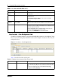
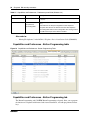
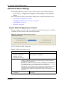
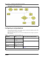
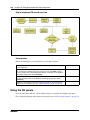
The Scheduled Services - Settings and Schedules panel has three distinct areas for configuration.
•
•
•
The table in the top frame allows you to determine which schedules are active for the system
for routing, restriction, and ringing schedules.
The table in the top frame to the right sets the time periods within each schedule for each day
of the week.
The table in the bottom frame allows you to rename schedules.
Click one of the following links to connect with the type of information you want to view:
Panels
Related panels or tasks
Feature
“Configuring scheduled service”
on page 31
Alternate routes for routing
schedules in the BCM 4.0
Networking Configuration Guide
(N0060606)
“Control telephone” on page 225
“Configuring schedule names and
timers” on page 30
“Ring Groups - Line Settings tab”
on page 97
Restriction filters in the BCM 4.0
Networking Configuration Guide
(N0060606)
“Restrictions (Line and Remote) in
the BCM 4.0 Networking
Configuration Guide (N0060606)
“Restrictions main tab” on page 65
Class of Service table in the
BCM 4.0 Networking Configuration
Guide (N0060606)
Click the navigation tree heading to access general information about Ring Group management.
Schedules are activated and deactivated through control telephones. Refer to “Control telephone”
on page 225.
BCM 4.0 Device Configuration Guide
30
Chapter 4 System schedule settings and services scheduling
Restriction and Routing services require a service control password before users are allowed to
change scheduling on a control telephone. The Service Control Password field on this panel allows
you to delete a current entry, and add a new password. Make a note of the password; the panel
displays only asterisks.
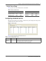
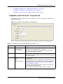
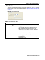
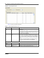
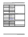
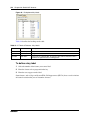
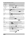
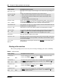
Configuring schedule names and timers
The tables on this panel allow you to change the names of the schedules, and to determine when
the schedules, which are set to automatically execute, are deployed. Any changes to these settings
affect all services that use schedules.
Figure 5 Schedule names and timers
Table 3 describes the fields on the subpanel tables.
Table 3 Schedule common settings
Attribute
Value
Description
<alphanumeric>
Double-click the field, and enter a descriptive name for the schedule.
Schedules
Schedule
Schedule Times
For each schedule, there are timers for the seven days of the week.
Day
<seven days>
Start Time
00:00 to 12:00
a.m.-p.m./24:00
This is the time when the schedule starts, and any previously-running schedules
stop.
Use a 12-hour or 24-hour format. If the entry is less than 12:00, the system
prompts for a day period setting.
00:00 = schedule is off
start and stop are the same = schedule runs for 24 hours
start: 22:00/stop: 06:00 = schedule starts at midnight, runs until 6 a.m., then
starts again at 10 p.m. (22:00).
Stop Time
00:00 to 12:00
a.m.-p.m./24:00
This is the time when the schedule stops.
N0060600
Chapter 4 System schedule settings and services scheduling
31
Default time settings
Table 4 provides a list of the default times for each schedule.
Table 4 Default schedule times
Schedule
Start Time
Stop Time
Schedule
Start Time
Stop Time
Schedule 1: Night
23:00
07:00
Schedule 4:
00:00
00:00
Schedule 2: Evening
17:00
23:00
Schedule 5:
00:00
00:00
Schedule 3: Lunch
12:00
13:00
Schedule 6:
00:00
00:00
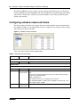
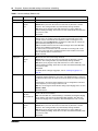
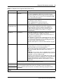
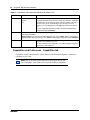
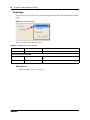
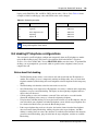
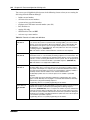
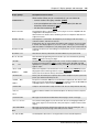
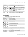
Configuring scheduled service
The table in the top frame lists all schedules available on the system. Configure the settings for the
schedules that you are using for your system.
Figure 6 Services table
Table 5 describes the fields under Scheduled Services.
Table 5 Service settings (Sheet 1 of 2)
Attribute
Value
Service control <alphanumeric>
password
Description
Restriction and Routing schedules require the user to enter a password on the
control telephone before scheduling can be changed.
If you forget the password, enter a new password.
BCM 4.0 Device Configuration Guide
32
Chapter 4 System schedule settings and services scheduling
Table 5 Service settings (Sheet 2 of 2)
Attribute
Value
Description
Schedule
<read-only>
These are the schedules that are available on the system.
Routing Svc
Off
Manual
Auto
Off prevents the service from being activated.
Manual allows you to turn the service on and off at any time from a control
telephone. This setting overrides any automatically-running schedules.
Auto allows you to program a stop and start time for a service under the
Common Settings heading. These times are then automatically executed when
the service is active.
Default: Off
Overflow
<check box>
If all the lines used by a route are busy when a call is made, you can program
Routing service to overflow to the route used for normal mode. If the call is
routed to use the normal mode, the telephone sounds a warning tone and
displays the message Expensive route. The caller then can release the
call to avoid the toll charges or can continue.
Tips: A schedule must be active for overflow routing to be in effect. Overflow
routing is not available in normal mode.
You must create an overflow route to be used with each routing code. In this
way, every route used with a scheduled mode that has overflow service must
have an alternate route in normal service.
Default: Cleared
Ringing Svc
Off
Manual
Auto
Off prevents the service from being activated.
Manual allows you to turn the service on and off at any time from a control
telephone. This setting overrides any automatically-running schedules.
Auto allows you to program a stop and start time for a service under the
Common Settings heading. These times are then executed automatically when
the service is active.
Default: Off
For details about setting up ring groups, refer to “Creating ring groups” on
page 95.
Trunk Answer
<check box>
Trunk answer enables you to answer, from any telephone, an external call that
is ringing at another telephone in your office, if the Ringing Service is active on
that line at the time of the call. If the service is not active, you cannot answer the
call.
Trunk answer is useful if the other telephones are not assigned the same lines
as the telephone you are using to answer the call.
Note: You can change the Trunk Answer setting only if Ringing service is set to
Manual or Auto.
Default: Selected
Extra Dial Set
None
DN <XX>
DN <control set>
The Extra dial set attribute allows you to assign an additional telephone to
receive calls for each schedule.
Note: The extra dial set is activated during a schedule by entering the Ringing
service feature code from the assigned direct dial telephone. This does not
activate the Ringing service, unless the direct dial telephone is also a control
set.
Restriction Svc Off
Manual
Auto
N0060600
Off prevents the service from being activated.
Manual allows you to turn the service on and off at any time from a control
telephone. This setting overrides any automatically-running schedules.
Auto allows you to program a stop and start time for a service under the
Common Settings heading. These times are then executed automatically when
the service is active.
Default: Off
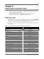
33
Chapter 5
System features and feature codes
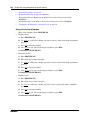
•
•
“BCM feature codes” on page 33 provides a complete list of the feature codes that can be
accessed from digital and IP telephones.
“Button programming features” on page 36 provides a list of the features that are
programmable under the DN record Button Programming heading.
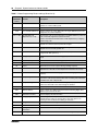
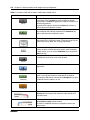
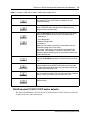
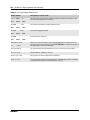
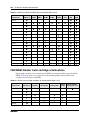
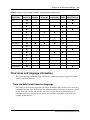
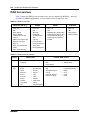
BCM feature codes
The following provides a quick reference for BCM features available by pressing the FEATURE
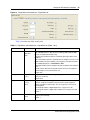
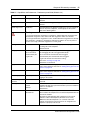
button on M-series telephones, Business Series Terminals (BST series), and IP telephones. Table 6
provides feature names sorted alphabetically, and numerically by feature code.
Refer to the user documentation for the specific product to find out how to use the codes on each
type of telephone.
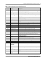
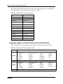
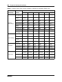
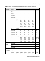
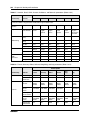
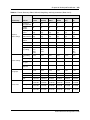
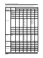
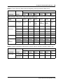
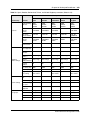
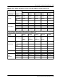
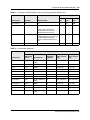
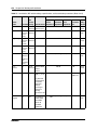
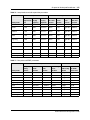
Table 6 Features sorted by feature name and by activation code (Sheet 1 of 4)
Sorted by feature name
Feature name
Sorted by activation code
FEATURE
<code>
FEATURE
<code>
Feature name
Alarm time (room set)
875
0
Speed Dial - Activate
Alarm time - Cancel
#875
*0
Button inquiry
Alarm time (HS admin set)
877
1
Messages - Send
Autodial - External
*1
#1
Messages - Cancel Send
Autodial - Internal
*2
*1
Autodial - External
Auto Hold
73
2
Ring Again
Auto Hold - Cancel
#73
#2
Ring Again - Cancel
Background Music
86
*2
Autodial - Internal
Background Music - Cancel
#86
3
Conference Call
Button inquiry
*0
*3
Memory buttons - Program
Contact Center agent login/log out
904
4
Call Forward
Contact Center agent make busy/ready
908
#4
Call Forward - Cancel
Contact Center queue status
909
*4
Speed Dial - Add, change
Call Charge Indication
818
5
Last Number Redial
Call Duration Timer
77
*501
Language - Primary
Call Forward
4
*502
Language - Alternate
Call Forward - Cancel
#4
*503
Language - Alternate 2
Call Forward to Voice Mail
984
*504
Language - Alternate 3
Call Information
811
*510
Time zone readjust (IP telephones)
BCM 4.0 Device Configuration Guide
34
Chapter 5 System features and feature codes
Table 6 Features sorted by feature name and by activation code (Sheet 2 of 4)
Sorted by feature name
Feature name
Sorted by activation code
FEATURE
<code>
FEATURE
<code>
Feature name
Call Log - Delete items (autobumping)
815
Call Log - Manual
813
Call Log - View information
812
*537
Find oldest SWCA
Call Log options
*84
*538
Find newest SWCA
Call Log password
*85
*550
Silent Monitor
Call Park
74
*6
Ring Type
Call Queuing
801
60
Page
Camp-on
82
61
Page - Internal (telephone speakers)
Class of Service
68
62
Page - External (external speakers)
Conference Call
3
63
Page - Combined (internal and
external)
Contrast adjustment
*7
64
Line Pool
Dialing Mode
*82
65
Messages - View
Directed Pickup
76
66
Voice Call
Display Voice Mail DN, skillset or IVR DN
985
67
Saved Number Redial
Do not Disturb
85
68
Class of Service
Do not Disturb - Cancel
#85
69
Priority Call
Exclusive Hold
79
*7
Contrast adjustment
*521 to *536
System Wide Call Appearance
(SWCA)
Voice Mail Leave Message
980
70
Transfer
Group Listening
802
#70
Transfer - Cancel
Group Listening - Cancel
#802
71
Link
Group Pickup
75
73
Auto Hold
IP Services list
*900
#73
Auto Hold - Cancel
IP Hot desking
*999
74
Call Park
Language - Primary
*501
75
Group Pickup
Language - Alternate
*502
76
Directed Pickup
Language - Alternate 2
*503
77
Call Duration Timer
Language - Alternate 3
*504
78
Pause
Last Number Redial
5
79
Exclusive Hold
Line buttons - Move
*81
*80
Ring Volume
Line Pool
64
*81
Line buttons - Move
Line Redirection
84
82
Camp-on
Line Redirection - Cancel
#84
*82
Dialing Mode
Link
71
83
Privacy (on/off)
Long tones
808
84
Line Redirection
Malicious call identification (MCID)
897
#84
Line Redirection - Cancel
Memory buttons - Program
*3
*84
Call Log options
Messages - Send
1
85
Do not Disturb
N0060600
Chapter 5 System features and feature codes
35
Table 6 Features sorted by feature name and by activation code (Sheet 3 of 4)
Sorted by feature name
Feature name
Sorted by activation code
FEATURE
<code>
FEATURE
<code>
Feature name
Messages - Cancel Send
#1
#85
Do not Disturb - Cancel
Messages - View
65
*85
Call Log password
Name and number blocking
819
86
Background Music
Name and number blocking - Cancel
#819
#86
Background Music - Cancel
Page
60
88
Voice Call Deny
Page - Combined (internal and external)
63
#88
Cancel Voice Call Deny
Page - External (external speakers)
62
800
Trunk Answer
Page - Internal (telephone speakers)
61
801
Call Queuing
Pause
78
802
Group Listening
Priority Call
69
#802
Group Listening - Cancel
Privacy (on/off)
83
803
Time
Record call
989
804
Wait for dial tone
Ring Again
2
805
Test telephone display
Ring Again - Cancel
#2
806
Static Time
Ring Type
*6
#806
Static Time - Cancel
Ring Volume
*80
807
Ringing (Signal) Call
Ringing (Signal) Call
807
808
Long tones
Room condition (Room set)
876
811
Call Information
Room condition (HS admin set)
878
812
Call Log - View information
Room occupancy
879
813
Call Log - Manual
Run/Stop
*9
815
Call Log - Delete items
(autobumping)
Saved Number Redial
67
818
Call Charge Indication
Silent Monitor
*550
819
Name and number blocking
Speed Dial - Add, change
*4
#819
Name and number blocking - Cancel
Speed Dial - Activate
0
870
View active services
Static Time
806
871
Turn Ringing service on
Static Time - Cancel
#806
#871
Turn Ringing service off
System Wide Call Appearance (SWCA)
*521 to
*536
872
Turn Restriction service on
#872
Turn Restriction service off
Find available SWCA
*520
873
Turn Routing service on1
Find oldest SWCA
*537
#873
Turn Routing service off
Find newest SWCA
*538
875
Alarm time
Test telephone display
805
#875
Alarm time - Cancel
Time
803
876
Room condition (Room set)
Time zone adjust (IP telephones)
*510
877
Alarm time (HS admin)
Transfer
70
878
Room condition (HS admin)
Transfer - Cancel
#70
879
Room occupancy
BCM 4.0 Device Configuration Guide
36
Chapter 5 System features and feature codes
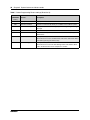
Table 6 Features sorted by feature name and by activation code (Sheet 4 of 4)
Sorted by feature name
Feature name
Sorted by activation code
FEATURE
<code>
FEATURE
<code>
Feature name
Transfer to mailbox
986
897
Malicious call identification (MCID)
Trunk Answer
800
*9
Run/Stop
Turn Restriction service off
#872
*900
IP Services list
Turn Restriction service on
872
904
Contact Center agent login/log out
Turn Ringing service off
#871
908
Contact Center agent make busy/
ready
Turn Ringing service on
871
909
Contact Center queue status
Turn Routing service off
#873
980
Voice Mail Leave Message
Turn Routing service on1
873
981
Voice Mail login
View active services
870
982
Voice Mail Operator settings
Voice Call
66
984
Call Forward to Voice Mail
Voice Call Deny
88
985
Voice Call Deny - Cancel
#88
Display Voice Mail DN, skillset, or
IVR DN
Voice Mail direct
988
986
Transfer to mailbox
Voice Mail Interrupt
987
987
Voice Mail Interrupt
Voice Mail login
981
988
Voice Mail direct
Voice Mail Operator settings
982
989
Record call
Wait for dial tone
804
*999
IP Hot desking
Note
1Contact your System Administrator for the service control password.
Button programming features
The following describes the features available for Button Programming (Configuration >
Telephony > Sets > All DNs > Capabilities and Preferences > Button Programming).
Note that some of these features require other system settings in order to work.
•
N0060600
Some of the buttons are controlled by features under Configuration > Telephony > Sets >
Active Sets > Capabilities. Paging is an example of a feature that requires other settings.
Chapter 5 System features and feature codes
•
37
Some features also require that the service be available on the line from your telephone service
provider. The types of lines provided are also determined by the region chosen for your
system. MCID (malicious call identification) is an example of this type of feature.
Table 7 Button Programming Feature settings (Sheet 1 of 4)
Set command
(FEATURE
Feature
<code>)
Description
None
Indicates a button that is configured for button programming, but nothing
has been entered.
0
Speed dial
Activates the speed dial feature. The telephone prompts the user for a
speed dial code.
1
Send message
Allows the user to send a message to another DN on the system.
#1
Cancel send message
Allows the user to cancel a message that was sent to another set within
the network.
2
Ring again
Turns on the Ring again feature.
3
Conference/Transfer
Initiates a conference between user and two parties.
4
Call forward
Allows the user to enter a number to forward all calls.
Note: Allow redirect must be selected to forward calls outside of the
system.
5
Last number redial
Causes set to redial the last number that was dialed.
*5
Language choice
Allows the user to select the language in which prompts are displayed.
60
Page - general
Initiates a page.
61
Page - Internal
Allows the user to page internal to a specific zone, which is identified
within the Button programming. (For example F611 internal zone 1, F610
page internal all zones.)
62
Page - External
Allows the user to page through the speaker on a specific telephone.
63
Page - speaker and zone Allows the user to page through both the internal sets, and externally
connected paging equipment to a specific zone, which is identified within
Button programming.
64
Line pool
Allows the user to access a line pool. The pool this button accesses is
specified during Button Programming for this feature.
65
Reply message
Allows the user to access messages, and send a reply to the message
sender.
#65
Cancel message waiting
Allows the user to cancel the message waiting indicator.
66
Voice call
Allows the user to make an announcement, or begin a call through the
speaker of another telephone.
67
Saved number redial
Allows the user to redial a number that was saved while on a call.
68
Restriction override
Allows the user to override any restrictions on the set or line with a CoS
password.
69
Priority call
Allows the user to priority call an internal DN that is currently busy.
*7
Contrast
Allows the user to adjust the contrast of the display screen.
70
Transfer
Allows the user to transfer an existing call to another telephone or
external number.
BCM 4.0 Device Configuration Guide
38
Chapter 5 System features and feature codes
Table 7 Button Programming Feature settings (Sheet 2 of 4)
Set command
(FEATURE
Feature
<code>)
Description
71
Link
Activates the Link command, which allows the user to access special
features on a remote PBX system.
74
Call park
Allows the user to park a call.
*520
Find available SWCA key System searches for a free SWCA key among the SWCA keys that are
assigned to the current telephone.
*521 to *536
System Wide Call
Appearance (1 to 16)
Non-intercom calls are associated with an available SWCA key when the
call is answered, originated, or placed on Hold.
Features that interact with this feature: Hold, telephone keys, outgoing
and incoming calls.
*537
Find oldest SWCA call
System searches among the SWCA keys assigned to the telephone, and
unparks the call that has been parked the longest.
*538
Find newest SWCA call
System searches among the SWCA keys assigned to the telephone, and
unparks the most recently parked call.
*550
Silent monitor
Allows the user to monitor hunt group calls. (Telephone must be
assigned with SM supervisor.)
75
Group pickup
Allows the user to answer a call ringing telephone within the Pickup
group.
76
Directed pickup
Allows the user to answer any ringing telephone within the same system.
77
Call timer
Allows the user to see the call duration timer.
78
Pause
Allows the user to insert a pause during a dialing sequence.
79
Exclusive hold
Allows the user to place a call on hold at the current telephone. All
appearances of the call on other telephones indicate the line is busy.
800
Trunk answer
Allows the user to answer a ringing line while in a ringing service. (If
enabled).
801
Call queuing
Allows the user to answer calls in order when several calls arrive in rapid
succession. Calls are presented in this order: incoming calls, timed-out
forwarded calls, then camped calls.
802
Group listening
Activates the speaker on the set to allow a group of people to hear a call.
But the user must talk to the caller through the handset.
803
Time
Briefly displays the current time.
804
Wait for dialtone
Places a pause in a dialing string that holds the following digits until a
dialtone is perceived on the line.
806
Static date and time
First line displays the date and time.
807
Ringing (Signal) call
Directly rings another telephone inside the system when an extension is
entered after the feature is selected. This is the same process as
pressing an intercom button and dialing an extension.
808
Long tones
Allows the user to send long DTMF tones.
811
Call information
Allows the user to view information about a current call.
812
Call log - view
information
Allows the user to view call log information.
813
Call LogIt
Allows the user to add the current call to the call log manually.
N0060600
Chapter 5 System features and feature codes
39
Table 7 Button Programming Feature settings (Sheet 3 of 4)
Set command
(FEATURE
Feature
<code>)
Description
815
Call logs autobumping
Allows the user to select if the system will remove the oldest log item
manually when the log space fills.
818
Call charge indication
Allows the user to view the charges for a call (available on DASS2 and
ETSI Euro trunks only).
819
ONN blocking
Allows the user to block the call information from the telephone for an
outgoing call.
82
Camp-on
Allows the user to transfer and camp an external call on another
telephone in the system.
83
Privacy control
Allows the user to change the line privacy setting on the current call.
84
Line redirection
Allows the user to redirect a line on their telephone to an external
number.
85
Do not disturb
Allows the user to block incoming calls from ringing on the telephone.
86
Background music
Allows the user to play music provided by a background music source
through the speaker on the telephone.
870
Service mode status
Allows the user to view the current service mode being used.
871
Ringing service
Allows the user to change the ringing service mode.
872
Restriction service
Allows the user to change the restriction service mode.
873
Routing Service
Allows the user to change the routing service mode.
88
Voice call deny
Allows the user to deny other users from Voice Calling their set.
897
MCID
(Malicious Call Identification)
Allows the user to query the system for information about a call within 25
seconds after the user hangs up, but before the caller hangs up.
*501
Language choice
Provides a menu that allows you to choose the language for the display
prompts on the telephone.
Contrast
Digital telephones only.
Sets the level of contrast for the telephone display.
904
CC agent login/log out
Allows the user to log in or out of ACD.
905
CC supervise
Allows the CC supervisor to monitor CC agent calls.
906
CC supervisor help
Allows the CC agent to request help from a CC supervisor.
907
CC activity code
Allows the CC agent or supervisor to enter activity codes for reporting.
908
CC agent make Not
ready/ready
Allows the user to indicate ready or Not ready status on ACD.
909
CC skillset status
Allows the user to view the status of queued calls on ACD.
980
Voice mail Leave
Message
Allows the user to log into voice mail box to leave a message.
981
Voice mail login
Opens your mailbox to play your messages and to access mailbox
options.
982
Voice mail operator
settings
Allows the user to set the parameters for the voice mail operator.
984
Call forward to voice mail Forwards all calls to your voicemail.
*7
BCM 4.0 Device Configuration Guide
40
Chapter 5 System features and feature codes
Table 7 Button Programming Feature settings (Sheet 4 of 4)
Set command
(FEATURE
Feature
<code>)
Description
985
Display voice mail DN
Displays the voice mail, skillset, or IVR DN.
986
Transfer to mailbox
Transfers an external call directly to a mailbox on the CallPilot system.
987
Voice mail interrupt
Intercepts a caller who is listening to your mailbox greeting or leaving a
message.
988
Voice mail direct
Dial an internal user via the name in the voice mail directory.
989
Record call
Record the call to your voice mail box. Must be enabled by the system
administrator.
*900
IP services list
IP telephones only.
Allows the user to access a feature menu. This is the same menu that is
accessed by pressing the Services key.
*999
IP Hot desking
IP telephones only.
Allows the user to access the Hot desking feature. This feature allows
calls to be diverted from one IP telephone to another.
N0060600
41
Chapter 6
DN records parameters
The DN record defines the specific function of each telephone within the system.
The following paths indicate where to access DN record parameters in Element Manager and
through Telset Administration:
•
•
Element Manager: Configuration > Telephony > Sets > All DNs
Telset interface: **CONFIG > Terminals and Sets
Other areas of programming that affect how each telephone functions include:
•
•
system settings (“Global telephony settings” on page 71)
telephone model
The DN records panel is a multilayered panel with multiple tabs. Although all panels show up for
all models, not all models require configuration for all panels. Refer to the task and feature
programming links to determine specific configuration. For information on programming a
Doorphone refer to the BST Doorphone documentation.
The panel tabs links provide a general description of each panel and definitions of each panel field.
Click one of the following links to connect with the type of information you want to view:
Panel tabs
Tasks
Features
“Main panel tabs: common fields” on
page 42
“Common procedures: copying and
renumbering DNs” on page 69
“Feature configuration: Answering
calls” on page 193
“Line Access tab” on page 44
“Configuring telephones: Digital
telephones” on page 119
“Feature configuration: Making
calls” on page 213
“Line Access - Line Assignment
tab” on page 46
“Configuring analog telephones and “Hotline telephone” on page 225
devices” on page 115
“Line Access - Line Pool Access
tab” on page 48
“Control telephone” on page 225
“Line Access - Answer DNs tab”
on page 49
“Supervisor telephone for silent
monitoring” on page 227
“Capabilities and Preferences main tab”
on page 50
“Capabilities and Preferences Capabilities tab” on page 52
“Capabilities and Preferences Preferences tab” on page 56
“Features to set up telephone set
features” on page 187
“Auxiliary ringer” on page 190
“Capabilities and Preferences ATA Settings tab” on page 62
“Capabilities and Preferences - IP “Configuring telephones: IP
Terminal Details tab” on page 64 telephones” on page 135
“Global VoIP features” on page 139
BCM 4.0 Device Configuration Guide
42
Chapter 6 DN records parameters
Panel tabs
Tasks
Features
“Capabilities and Preferences Button Programming tab” on
page 58 (includes CAP/KIM
button programming)
“Default memory button
programming for telephones” on
page 149
“Creating an enhanced CAP station”
on page 229
“Capabilities and Preferences User Speed Dial tab” on page 61
“System features and feature
codes” on page 33
“Restrictions main tab” on page 65
“Call security: Restriction filters” in
the BCM 4.0 Networking
Configuration Guide (N0060606)
“Restrictions - Set Restrictions
tab” on page 66
“Configuring remote access
packages” in the BCM 4.0
Networking Configuration Guide
(N0060606)
“Restrictions - Line/Set
Restrictions tab” on page 67
“Restrictions (Line and Remote)” in
the BCM 4.0 Networking
Configuration Guide (N0060606)
Click the navigation tree heading to access general information about DN records.
Main panel tabs: common fields
The Line Access, Capabilities and Preferences, and Restrictions tabs included in the Main panel,
all display the same four columns as shown in Table 8.
N0060600
Chapter 6 DN records parameters
43
Figure 7 Main Panel tabs
Table 8 Common columns for the main panels (Sheet 1 of 2)
Attribute
Value
Description
DN
<numeric>
This number is unique to each telephone record. The number
identifies the telephone to the system. DN start digits and DN length
are configured during system setup.
Digital and analog telephone DNs map one-to-one with ports on
module connections. IP telephone DNs do not map to specific ports;
however, a keycode is required to activate the feature.
Model
Analog
7000
7100
7208
7310/7316
7316E
7324
2004/2050
2002
2001
2007
2033
2050
DMC prtb
1120E, 1140E
Other
This heading appears for telephones in the digital DN range, from
the Start DN (default: 221) up to DN 433. Choose the setting that is
appropriate for the telephone you want to configure.
This field is read-only if the telephone is already attached or
registered to the system.
• 7310/7316: also 7406 cordless digital phone
• 7316E: also for 7316E digital phone with KIMs
(Model 7000 phones are supported in Europe only)
Name
<up to seven alphanumeric
characters>
Use this field to provide a more specific description of the telephone,
such as the last name of the user, the location, or the actual
extension number if it is different than the DN number.
Also refer to “Programming name display (outgoing)” in the BCM 4.0
Networking Configuration Guide (N0060606).
BCM 4.0 Device Configuration Guide
44
Chapter 6 DN records parameters
Table 8 Common columns for the main panels (Sheet 2 of 2)
Attribute
Value
Description
Port
<port number>
This number indicates the port number to which this DN
corresponds.
A group of port numbers relates to a specific station module installed
in your BCM. If you change the DN for a telephone, the port number
remains the same.
If you physically move a telephone with the relocation feature turned
on, the DN transfers to the new port, and the DN for that port
transfers to the vacated location.
Line Access tab
The Line Access tab displays the DNs table. Line access programming is performed using the
four tabs that appear in the details panel when a DN is selected. Refer to Figure 8.
•
•
•
•
Line Access - Properties tab
“Line Access - Line Assignment tab” on page 46
“Line Access - Line Pool Access tab” on page 48
“Line Access - Answer DNs tab” on page 49
Line Access - Properties tab
The administrator can use the properties tab to identify the public and private OLI of the selected
DN. You also identify where, and when, calls are forwarded.
N0060600
Chapter 6 DN records parameters
45
Figure 8 Properties tab
Table 9 describes these fields.
Table 9 Line Access tab fields (Sheet 1 of 2)
Attribute
Value
Description
Pub. OLI
<up to 12 digits>
This setting defaults to the DN of the device. The Public Network
Code concatenates to the beginning of this number to create the
entire public network number. The length of this number is
dependent on the country requirements.
This line identification number (OLI) appears on the telephone called
from this telephone over the public network. Also refer to “Public
network settings” in the BCM 4.0 Networking Configuration Guide
(N0060606).
North America: If the OLI contains the public network code, the
information in the Public Network code field is ignored. Therefore, it
is recommended that OLIs be programmed to the public received
number length, only. This allows a global change if the Public
Network Code is changed.
Also refer to “Configuring CLID on your system” in the BCM 4.0
Networking Configuration Guide (N0060606).
Priv. OLI
<numeric>
Define the originating line identification number (OLI) that appears
on the telephone being called from this telephone over a private
network.
Note: On systems running DID, this field is populated automatically
with the DN.
If the DN length or the Received # length are changed to be different
from each other, this field is cleared.
Also refer to “Configuring CLID on your system” in the BCM 4.0
Networking Configuration Guide (N0060606).
*If your system allows outgoing name and number blocking, the telephone must have a valid OLI.
BCM 4.0 Device Configuration Guide
46
Chapter 6 DN records parameters
Table 9 Line Access tab fields (Sheet 2 of 2)
Attribute
Value
Description
Fwd No
Answer
up to 24 digits
Enter the number to which you want to redirect unanswered
incoming calls.
Fwd Delay
2, 3, 4, 6, 10
Define the number of rings before the system forwards an
unanswered call.
This heading only appears after you enter a Call Forward No
Answer number and press Enter.
Default: 4
Fwd Busy
up to 24 digits
Redirect incoming calls when this telephone is busy with another
call.
Fwd All
up to 24 digits
This setting is the same as using FEATURE 4 at a telephone. When
this feature is active, all calls to this telephone are forwarded to the
destination entered in this field.
If you are forwarding calls to a remote location, ensure that you
include the required destination/access codes.
A user can press FEATURE #4 to cancel this feature.
Line Access - Line Assignment tab
Use the line assignment settings to assign physical trunks and target lines to each telephone. Target
lines are used as incoming only. Other lines can be used to both place and answer calls, if they are
configured to do so.
Figure 9 Line Access - Line Assignment tab
Table 10 describes the fields on this panel.
Table 10 Telephone line assignment fields (Sheet 1 of 3)
Attribute
Values
Description
Line
<read-only>
These are the lines on which this telephone can receive calls. If the
line is a two-way line (DID), the user can also use the line to make
calls.
Also refer to “Configuring Lines” in the BCM 4.0 Networking
Configuration Guide (N0060606).
N0060600
Chapter 6 DN records parameters
47
Table 10 Telephone line assignment fields (Sheet 2 of 3)
Attribute
Values
Description
Appearance Type
Ring only, Appr&Ring,
Appr only
Select how a call on this line appears on the telephone.
If you choose Appr&Ring or Appr only, you can have as many
simultaneous DID calls as there are target line button appearances.
If you choose Ring only, you can have as many simultaneous DID
calls as you have intercom buttons.
Note: The BCM does not support a mixture of Appr only and Ring
only appearances for the same line.
7000 or 7100 digital phones default to Ring only.
(Model 7000 phones are supported in Europe only)
Appearances
(for target lines, only)
<1-255>
Select the number of appearances of a target line.
Note: The number of appearances that can be assigned to a
telephone depends on how many buttons with indicators are
available. Target line appearances cannot overwrite other line
appearances, Answer DNs, Intercom buttons, or assigned
Handsfree button.
Caller ID set
<check box>
This prompt only appears for target lines, and for any analog lines
that provide CLID through an GATM (not all markets).
When enabled, the telephone displays call information when it is
available for a call before answer.
When disabled, no call information is displayed for this line. Choose
this setting if the telephone does not have a display, or if you do not
want call information displayed to the user. Disabling this function
can reduce system resource requirements.
Note: Only 30 telephones can have this field enabled for any given
line.
Vmsg Set
<check box>
Select whether an indicator shows on the telephone for a voice
message waiting on an external voice message system.
The line must appear on the receiving telephone.
Note: The Message Waiting Indicator (MWI) is currently supported
exclusively by Meridian Mail and CallPilot and SL-100, and
DMS-100.
MCDN note: If your system is part of an MCDN network connected
to a Meridian 1 system, and you are using the voice mail system off
the Meridian 1, you must enable this field.
Analog lines connected to legacy analog ASM station modules, and
analog telephones attached to an ATA device, do not provide visible
message waiting indication. Analog telephones connected to a
GASM8 support message indicators, if the telephone is set up to
receive them.
Note: Contact your voice message service provider to find out if your voice message service
works with BCM, or if you have any problems with your service.
Priv. Received #
(Target lines only)
Pub. Received #
(Target lines only)
These fields reflect the settings defined under target lines.
These are the digit strings that the system uses to identify a call for this telephone.
Refer to “Trunk/Line Data, main panel” in the BCM 4.0 Networking Configuration Guide
(N0060606).
Actions
BCM 4.0 Device Configuration Guide
48
Chapter 6 DN records parameters
Table 10 Telephone line assignment fields (Sheet 3 of 3)
Attribute
Values
Description
Add
To add a line to a telephone:
1. On the System DNs table (Line Access tab), choose the DN record where you want to
add lines.
2. Under the Assigned Lines table in the bottom panel, click Add.
3. Enter a line number in the dialog box.
4. Click OK to save the line to the list.
Delete
1. On the System DNs table (Line access tab), choose the DN record where you want to
delete lines.
2. On the Assigned Lines table in the bottom panel, select a line you want to delete.
3. Click Delete.
4. Click OK to confirm the selection.
Line Access - Line Pool Access tab
Use the Line Pool Access tab to add line pools to a telephone record.
Figure 10 Line Access - Line Pool Access tab
These shared pools of lines enables many users to use fewer lines for connections, where dedicated
lines are not practical or not desirable. If all lines in the pool are taken, the user receives a busy
signal.
Some trunks, such as PRI and VoIP, must be put into line pools. For outgoing calls, the line pools
are assigned to the telephones that call out over these trunks.
All lines except PRI and BRI ETSI-QSIG lines are configured in line pools A to O. PRI and BRI
ETSI-QSIG lines can be configured into line pools BLOC-A to BLOC-F.
N0060600
Chapter 6 DN records parameters
49
Table 11 describes the access fields on this panel.
Table 11 Line Pool Access fields
Attribute
Values
Description
Line Pool
<read-only>
This is a list of available line pools. Choose the ones that provide the
outgoing call access you want for the telephone.
Actions
Add
1.
2.
3.
4.
On the Line Access tab, choose the DN record, to which, you want to add line pools.
On the Line Pools Access tab in the bottom panel, click Add.
Enter a line pool in the dialog box.
Click OK on the dialog box to save the line pool to the list.
Delete
1.
2.
3.
4.
On the Line Access tab, choose the DN record, of which, you want to delete line pools.
On the Line Pools Access tab in the bottom panel, select a line pool you want to delete.
Click Delete.
Click Yes.
Line Access - Answer DNs tab
Program a telephone to provide automatic call alerting and call answering for other telephones in
the system. The DNs of the other telephones are referred to as Answer DNs.
Figure 11 Line Access - Answer DNs tab
Table 12 describes the access fields on this panel.
Table 12 Line Pool Access Fields - Answer DNs (Sheet 1 of 2)
Attribute
Values
Description
DN
<DN number>
From the main panel DN list.
BCM 4.0 Device Configuration Guide
50
Chapter 6 DN records parameters
Table 12 Line Pool Access Fields - Answer DNs (Sheet 2 of 2)
Attribute
Values
Description
Appearance Type
Appr&Ring, Appr only,
Ring only
Define how calls to the Answer DN will present on this telephone:
Appr&Ring: Call prompt appears beside the Answer DN button, and
the telephone rings.
Appr only: Call prompt appears beside the Answer DN button.
Ring only: Telephone rings.
Notes:
Every answer DN you assign to a telephone automatically designates an appearance on the answer telephone
beside a button with an indicator, if one is available. Answer DNs overwrite feature assignments to buttons with
indicators. They do not overwrite line, Hunt group, intercom, or handsfree assignments.
If no buttons are available on the telephone, ensure that you program the Answer DN as Ring only. In that case,
when a call comes in to the other telephone, the user receives a ring tone.
Actions
Add
You can add a maximum of eight Answer DNs per telephone.
1. On the Line Access tab, choose the DN record where you want to add Answer DNs.
2. Under the Answer DNs tab, click Add.
3. Enter the appropriate DN in the dialog box.
4. Click OK to save the entry.
5. On the Answer DNs tab, select the Appearance type field beside the Answer DN you just
entered, and choose the appropriate appearance type.
Programming Note: If the telephone has memory buttons with display designators, the
system automatically assigns Answer DNs to buttons starting at the bottom right row of
buttons. If the telephone has Handsfree assigned to a memory button, the Answer DNs start
above that button. If the telephone has no memory buttons with display, ensure that you
choose Ring only as the Appearance type.
Delete
1.
1.
2.
3.
On the Line Access tab, choose the DN record where you want to delete Answer DNs.
On the Answer DNs tab, select the Answer DN line you want to delete.
Click Delete.
Click Yes.
Capabilities and Preferences main tab
Capabilities settings control how the system interacts with individual telephones, and how the
telephones receive calls.
Preferences control how the telephone itself works. These settings also can be set by users at the
telephones using feature codes.
Modify the Capabilities and Preferences for a particular DN by changing the values on the
following subpanels.
•
•
•
•
•
N0060600
“Capabilities and Preferences - Properties tab” on page 51
“Capabilities and Preferences - Capabilities tab” on page 52
“Capabilities and Preferences - SWCA Call Group tab” on page 55
“Capabilities and Preferences - Preferences tab” on page 56
“Capabilities and Preferences - Button Programming table” on page 58
Chapter 6 DN records parameters
•
•
•
51
“Capabilities and Preferences - Button Programming tab” on page 58
“Capabilities and Preferences - ATA Settings tab” on page 62
“Capabilities and Preferences - IP Terminal Details tab” on page 64
Capabilities and Preferences - Properties tab
The Properties settings control how calls are displayed, as well as assignment of control sets to
individual telephones.
Figure 12 Capabilities and Preferences - Properties tab
Table 13 describes the fields shown on the main Capabilities and Preferences tabbed panel.
Table 13 Capabilities and Preferences tabbed panel (Sheet 1 of 2)
Attribute
Values
Description
Prime Line
None, Pool (A to O),
I/C (intercom),
Line: <line number>
Choose the first line that the telephone selects when a call is made. PRI
Bloc pools are not valid selections for a Prime line.
When you assign a line pool as a prime line, the system searches
automatically for an idle line in the pool.
Intercom Keys
0 to 8
Assign the number of intercom buttons to a telephone.
Intercom buttons provide a telephone with access to internal and external
lines, and to line pools.
Control Set
DN: <any telephone
DN>
None
DN:221<start DN>*
The Control telephone attribute allows you to define a DN that acts as a
control telephone.
A control telephone is used to enable/disable Scheduled Services, such
as Restriction Services, for the telephones to which it is assigned. For
more information about services, see “System schedule settings and
services scheduling” on page 29.
You can assign several control sets for your system, but you can only
assign one control telephone per DN.
* If you change the Start DN, this number reflects that change.
BCM 4.0 Device Configuration Guide
52
Chapter 6 DN records parameters
Table 13 Capabilities and Preferences tabbed panel (Sheet 2 of 2)
Attribute
Values
Description
First Display
Name
Number
Line
Determine the call display information that appears first.
This feature depends on the services to which you subscribe. Call Display
information can contain the name of the caller, the number of the caller,
the name of the line in your BCM where the call enters. For each
telephone, you can determine the call display information that appears
first.
See also “Programming incoming CLID” in the BCM 4.0 Networking
Configuration Guide (N0060606).
Tips: The Call Information feature displays and toggles between the name and line number for
Call Display information.
Alpha tagging: If you are using the alpha tagging feature, choose Name. Refer to “Using alpha
tagging for name display (incoming)” in the BCM 4.0 Networking Configuration Guide (N0060606).
Auto Called ID
<check box>
Select whether you want to see on your display the extension number
and name of the telephone you call.
The Auto Called ID set for target lines is the same telephone that has an
appearance on that target line.
Capabilities and Preferences - Capabilities tab
Capabilities settings control how the system interacts with individual telephones, and how the
telephones receive calls.
Note: Not all the fields shown below necessarily appear for any one
type of telephone. Some fields relate to specific models of telephones.
N0060600
Chapter 6 DN records parameters
53
Figure 13 Capabilities and Preferences - Capabilities tab
Table 14 describes the fields on this panel.
Table 14 Capabilities and Preferences - Capabilities tab (Sheet 1 of 3)
Attribute
Values
Description
Handsfree
None
Standard
Auto
None: The handsfree feature is not available on all telephone models (7000
and 7100 digital phones, 2001 IP phones, DMC portables).(Model 7000
phones are supported in Europe only)
Standard: The handsfree feature is activated by pressing a button on the
telephone.
Auto: The handsfree feature is activated when the telephone receives a call.
Note: Handsfree must be enabled on any telephone that allows headsets.
For 7316E digital phones, set Handsfree to Auto.
7406 digital cordless phone: Handsfree must be enabled for this handset to
work.
Speaker volume: Note that the speaker volume returns to the telephone
default setting for each new handsfree call.
Default: Auto
Pickup group
None
1 to 9
Assigns this telephone to a pickup group (a group where all telephones ring
until one is answered).
Default: None
Page zone
Page zone
(1 to 6)
None
Assigns this telephone to a page zone.
A zone is any group of telephones that you want to group together for
paging, regardless of their location. You can assign one of six zones to
each telephone.
The maximum number of digital telephones in a page zone is 50.
The maximum number of digital and IP telephones in a page zone is 60.
Default: 1
Direct dial
Set 1 to Set 5
None
Defines whether you can call the direct dial telephone from this telephone
using the direct dial digit.
Default: 1
BCM 4.0 Device Configuration Guide
54
Chapter 6 DN records parameters
Table 14 Capabilities and Preferences - Capabilities tab (Sheet 2 of 3)
Attribute
Values
Description
Intrusion protection
level
None
Low
Med
High
If the break-in feature is allowed on any private network MCDN lines (PRI
SL-1) assigned to the telephone, you must define the level of intrusion for
each telephone. This determines if the user can use the feature, and to
what degree.
None: feature is turned off, user cannot break in on any calls
Low: user can only break into calls on other telephones with low level
protection
Med: user can break into calls on other telephones with low and
medium-level protection
High: user can break into calls on all other telephones with this feature
Default: None
HF answerback
<check box>
Defines whether you can answer automatically a voice call without lifting the
receiver, or pressing the Handsfree button.
Note: The feature is not available on models 2001, 7000 and 7100
telephones. (Model 7000 phones are supported in Europe only)
Speaker volume: Note that the speaker volume on the telephone returns to
the default volume setting determined by the telephone for each new
handsfree call.
Default: Selected
DND on Busy
<check box>
Defines whether an incoming call rings if you are already on another call.
Default: Cleared
Paging
<check box>
Defines whether you can make paging announcements from this telephone.
Default: Selected
Auto hold for incoming <check box>
page
Not selected - If the telephone is active when a page comes in, the page
does not come through the telephone set.
Selected - If the telephone is active when a page comes in, the call is
placed automatically on hold and the page continues.
Note - 7XXX digital phones:
• Condition - When this setting is enabled, an active call is on mute when
the page comes in.
• Results after page - The call is taken off hold, but is no longer muted.
Default: Cleared
Priority call
<check box>
Defines whether this telephone can interrupt calls or override Do Not
Disturb at another telephone.
Default: Cleared
Auto hold
<check box>
This setting determines if the system automatically places an active call on
hold if you answer or initiate another call.
If you do not select this box, the system drops the active call, unless you
press the HOLD button first, when you answer a call or initiate another call.
The user can change the Auto hold setting at their telephones by pressing
FEATURE 73.
SWCA note: Ensure this setting is selected for any telephones with
configured System Wide Call Appearance (SWCA) keys. Refer to “Sharing
calls by parking on SWCA buttons” on page 207
Default: Selected
N0060600
Chapter 6 DN records parameters
55
Table 14 Capabilities and Preferences - Capabilities tab (Sheet 3 of 3)
Attribute
Values
Description
Allow redirect
<check box>
Define whether this telephone allows assigned lines to be redirected.
This must be selected to allow call forwarding outside the network (external
call forward), including calls to a centralized voice mail system over a
private network.
Default: Cleared
Redirect ring
<check box>
Define whether the telephone rings briefly when a call on one of its lines is
redirected by the Line Redirection feature (FEATURE 84).
Also refer to “Trunk/Line Data, main panel” in the BCM 4.0 Networking
Configuration Guide (N0060606).
Default: Selected
Receive short tones
<check box>
Analog equipment, which is connected to the system with an internal or
external analog terminal adapter (ATA2), responds only to tone dialing
signals.
Select this setting only if you have analog equipment connected to a station
port.
Default: Cleared
Silent monitor
supervisor
<check box>
On two-line display telephones only, you can choose whether the telephone
can be used to allow the Silent Monitor feature. Select the check box to
allow this feature on this telephone.“Silent Monitor” on page 81“Monitoring
Hunt Groups” on page 107.
Default: Cleared
Capabilities and Preferences - SWCA Call Group tab
Although System-wide Call Appearance (SWCA) assignments are meant to be assigned to buttons
with indicators, you can assign SWCA assignments to a telephone without assigning them to
buttons using the fields on this panel. This is useful if you want to use the full range of SWCA
assignments.
Use the SWCA Call Group tabbed panel to enable or disable Call 1 to Call 16 assignments for
each sets. The administrator can configure the 16 SWCA feature codes on all the sets through
administration.
Users can park or retrieve calls on any SWCA assignment, even if the call is not directly assigned
to their telephone. However, the SWCA support codes (FEATURE *520, FEATURE *537 and
FEATURE *538) only search for SWCA assignments that are assigned to the telephone where the
feature is invoked. These codes are required for users who do not have buttons with indicators.
BCM 4.0 Device Configuration Guide
56
Chapter 6 DN records parameters
Figure 14 Capabilities and Preferences - SWCA Call Group tab
Capabilities and Preferences - Preferences tab
The Preferences headings allow you to program the same settings that users can perform at their
telephones, and the settings for configuring a telephone as a hotline. The telset admin options are
available only to digital telephones and IP telephones.
Figure 15 Capabilities and Preferences - Preferences tab panel
Table 15 describes the headings on the Preferences panel.
Table 15 Capabilities and Preferences - Preferences panel fields (Sheet 1 of 3)
Setting
Values
Language
Languages displayed Choose the language for the telephone display prompts.
are based on
telephone capabilities
and system software.
Dialing options
Standard dial
Automatic dial
Pre-dial
N0060600
Description
Determine how the telephone handles dialed information.
Standard: Lift the receiver and dial.
Automatic dial: Use for devices, such as fax machines where you
want the number to dial out without external cues.
Pre-dial: Dial the numbers, then lift the handset to allow the
telephone to dial the number.
Note: Not all devices show all three options.
Default: Standard dial
Chapter 6 DN records parameters
57
Table 15 Capabilities and Preferences - Preferences panel fields (Sheet 2 of 3)
Setting
Values
Description
Contrast
1 through 9
Adjust the contrast of the display.
Default: 4
Ring type
1, 2, 3, or 4
Select a distinctive ring pattern type for the telephone.
Default: 1
Distinct rings in use
<read-only>
This field indicates the distinct ring patterns, if any, are currently in
effect on any lines, telephones, or Hunt groups on the system.
Refer to the Warning below.
Warning:
If you assign a distinctive ring pattern to a telephone, and that distinctive ring pattern has
already been assigned to a line, all lines with that ring pattern will be reset to None.
If you assign a distinctive ring pattern to a line, and that distinctive ring pattern has already
been assigned to a telephone, all telephones with that ring pattern are reset to pattern 1.
You also can assign a distinctive ring pattern to a Hunt group.
Aux. ringer
<check box>
Determine whether an auxiliary ringer (if installed) rings for
incoming calls at this telephone.
Default: Cleared
Call log options
No autologging
No one answered
Unanswered by me
Log all calls
Select how you want the telephone to handle logging calls.
No autologging: No calls are logged automatically.
No one answered: Unanswered calls are logged.
Unanswered by me: Unanswered calls are logged.
Log all calls: All calls are noted in the call log.
Also refer to “Call log” on page 210.
Default: No one answered
Log space
<numeric>
Allocate a number of Call log spaces from a system-wide pool of
spaces to the telephone. Also refer to “Setting call log space for the
system” on page 210.
Log space
<numeric>
Allocate a number of Call log spaces form a system-wide pool or
spaces to the telephone. Also refer to “Setting call log space for the
system” on page 210.
Available log space
<read-only>
This setting indicates the total amount of space available for call
logging on the system.
Reset Call Log
Password
<button>
This button resets the password for the call log if users forget their
password.
Hotline type
None
Internal
External
This feature allows you to define a telephone number that
automatically dials when you lift the handset or press the Handsfree
button, on a telephone.
Default: None
•
DN:*
Direct dial set
Define the internal telephone you want to access.
DN:* The DN of the telephone that is automatically dialed when the
user lifts the handset.
Direct dial set: Automatically dials a telephone on the system
defined as a direct dial telephone (direct dial access code).
Note: If the direct dial telephone is on a remote node of the
network, ensure that the correct line pools are assigned to the
telephone to properly route the call.
Internal
BCM 4.0 Device Configuration Guide
58
Chapter 6 DN records parameters
Table 15 Capabilities and Preferences - Preferences panel fields (Sheet 3 of 3)
Setting
Values
Description
•
External number
Enter the complete call number for the external telephone you want
to access.
Pool:A
Use prime line
Use routing table
Enter the line you want the call to use. (This cannot be a target
line.)
Pool:A Refer to the line pool assignment for this telephone.
Use prime line: Refer to the General record for this telephone.
Use routing table: Refer to the routing tables. The routing code for
that table must be part of the External number.
External
Also refer to:
•
“Moving IP telephones” in the BCM 4.0 Telephony Device Installation Guide (N0060609).
Capabilities and Preferences - Button Programming table
Figure 16 Capabilities and Preferences - Button Programming Table
Capabilities and Preferences - Button Programming tab
The Button Programming and CAP/KIM Button Programming tab panels allow you to program
the buttons on a telephone with internal and external autodialers, and with programmed feature
keys.
N0060600
Chapter 6 DN records parameters
59
You also can use these panels to remove programming from a button, making it blank.
Figure 17 Button Programming and CAP/KIM Button Programming tabbed panels
Assigned lines, Hunt group designators, Answer DNs buttons, Intercom buttons, and Handsfree
buttons cannot be changed through these panels. They appear in read-only format.
BCM 4.0 Device Configuration Guide
60
Chapter 6 DN records parameters
Table 16 describes the possible settings for telephone buttons.
Table 16 Button programming fields (Sheet 1 of 2)
Setting
Values
Description
Model
7100
7208
7310/7316
7316E
7324
2004/2050
2001
2002
2007
2033
DMC prtb
1120E, 1140E
2210
2211
2212
If you have not yet connected a telephone, choose the model
of the telephone. This creates a number of defaults based on
the telephone capabilities.
This setting reflects whatever you set on the main table.
This field is read-only if the telephone is already attached or
registered to the system.
• 7310 also refers to the cordless 7406 cordless digital
phones.
• 7316E indicates both a stand-alone 7316E digital phone
and a 7316E digital phone connected to one or more Key
Indicator Modules (KIMs)
• 2002, 2004, IP phones connect to the Key Expansion
Module (KEM)
ISDN
These telephones have their own set of DN records.
• ISDN refers to any ISDN equipment
Other
This heading is used for the following types of devices:
• analog telephones
• Intl set (European only) is used for other types of
compatible telephones used in specific non-North
American markets, such as the 7000 digital phone.
Button Number (1-24)
<1-XX>
Use the telephone buttons to choose the features you want to
program.
Blank means that nothing is programmed on the button.
Example: New KIM modules have all blank buttons when they
are first installed.
Function
Blank
Feature
Internal autodial
External autodial
Choose the type of feature that you want to program on the
telephone buttons.
Blank means that nothing is programmed on the button.
Example: New KIM modules have all blank buttons when they
are first installed.
Feature
<feature code>
Use the arrow to choose the feature you want to program on
the button.
Internal autodial
<Internal DN>
Enter the DN number for the internal telephone you want the
telephone to dial by pressing this button.
Feature
<feature digits>
Includes digits for such features as system speed dial codes.
External autodial
<dialing codes plus dialout
string>
Enter the complete dial sequence for the external call. This
sequence depends on what you chose for the route in the
Value field.
Value
Digits
N0060600
Chapter 6 DN records parameters
61
Table 16 Button programming fields (Sheet 2 of 2)
Setting
Values
Description
Feature
<feature options>
Includes settings such as page zone.
External autodial
facility
Use prime line
Pool
Use routing table
Use line
Choose the route through which the telephone dials.
Prime line: the prime line assigned to the telephone.
Pool X: one of the pools assigned to the telephone.
Routing table: enter the routing code with the external
telephone number.
Use line X: one of the lines assigned to the telephone.
Option
Capabilities and Preferences - User Speed Dial tab
The speed dial numbers enables users to dial a number with fewer button presses than dialing the
entire dial string.
Note: User speed dials are only available from that users DN number.
Figure 18 Capabilities and Preferences - User Speed Dial tab
Table 17 describes the fields on this panel.
Table 17 Capabilities and Preferences - User Speed Dial panel fields (Sheet 1 of 2)
Setting
Values
Description
Speed Dial
Number
<71-94>
The number the user enters to dial the number entered in the External #
field. To increase the number of speed dials refer to “Configuring system
speed dial numbers” on page 85.
External
Number
<external telephone
number>
Enter the number the telephone automatically dials when the user speed
dial code is entered.
Note: Include the access codes for the route you choose.
BCM 4.0 Device Configuration Guide
62
Chapter 6 DN records parameters
Table 17 Capabilities and Preferences - User Speed Dial panel fields (Sheet 2 of 2)
Setting
Values
Description
Facility
Use prime line
Use routing table
Select the route you want the dialed number to take out of your system.
Note: Any line numbers or line pool codes that you specify must be
assigned to the telephone where the code is entered.
If you choose prime line, a prime line must be assigned to the telephone
where the code is entered.
Refer to “Line Access - Line Assignment tab” on page 46.
Actions
Add
1. On the Capabilities and Preferences tab, choose the DN record where you want to add User
Speed dials.
2. Under the User Speed Dial Numbers table, click Add.
3. Enter the appropriate speed dial number.
4. Click OK.
5. On the User Speed Dial, click the External Number field beside the number you entered.
6. Enter an external number to dial.
7. Click the Facility field beside the number you entered.
8. Enter how the number must be routed out of the system.
Delete
1. On the Capabilities and Preferences tab, choose the DN record where you want to delete User
Speed dial entries.
2. On the User Speed Dial Numbers table, click the user speed dial code or codes that you want to
delete.
3. Click Delete.
4. Click Yes.
Capabilities and Preferences - ATA Settings tab
Analog telephones have some settings that are specific to the analog connection. An analog
telephone can be connected to the system directly through an analog station port, either on the
Main Unit (in countries that support Main Unit Analog Stations) or through Analog Station Media
Bay Modules. These settings apply only when the DN record Model field is set to analog.
Analog telephones can also be connected by using an Analog Terminal Adapter (ATA2). The
digital station port can be on the main unit, or on a Digital Station Media Bay Module.
N0060600
Chapter 6 DN records parameters
63
Figure 19 Capabilities and Preferences - ATA Settings panel fields
Use the information in Table 18 to configure ATA settings.
Table 18 ATA settings
Attribute
Values
Description
ATA answer
timer
3, 5, 7, 10
Select the length of delay between the time you dial the last digit and when the
analog device is ready to receive DTMF tone.
Default: 7
ATA tones
<check box>
Not selected: No tones occur when a message is received (use for data equipment).
Selected: Tones occur when a message is received (use for analog telephones).
Default: Cleared
ATA use
On site
Off site
Select the location of the ATA2.
Note: Set the field to On site for all installations, except devices on a long loop. Set
the field to Off site to increase the audio level to devices that are remote to the
ATA2. This field has no effect for ASM and ASM8+ devices.
Note: OPX connections are not supported.
Default: On site
Msg indicate
None
Tone
Lamp
Select Tone to send a Message Tone through the telephone receiver when you
receive a message.
Select Lamp to turn on the Message Lamp when you receive a message.
Default: None
ATA device
Modem
Telephon
Devices connected to the system through an ATA can have connectivity issues over
BRI/PRI lines. To alleviate this, you can specify the type of device attached to the
analog line.
Modem supports 3.1 kHz audio, which requires a higher quality of service on the
ISDN trunks that modems and FAX machines require for reliable information
transfer. If the trunks cannot provide the higher level of service, the call fails.
Telephon supports speech paths, which require less quality on the trunk; if used for
FAX and/or modem, information transfer is unreliable.
Default: Modem
Disconnect
supervision
<check box>
If you have a modem or fax machine that does not disconnect automatically when
the caller disconnects, you can select this feature; the system then disconnects the
line from the device when it receives the disconnect signal from the far end. This
feature is supported only by ASM8+ modules.
Note: The line must be configured as supervised/guarded. Refer to “Properties” in
the BCM 4.0 Networking Configuration Guide (N0060606).
Default: Cleared
BCM 4.0 Device Configuration Guide
64
Chapter 6 DN records parameters
Capabilities and Preferences - IP Terminal Details tab
This is a single-terminal display of the terminal information that is also shown in the Telephony
Resources IP Terminal panel. Refer to “IP telephone set details” in the BCM 4.0 Networking
Configuration Guide (N0060606) for a detailed description of the fields and buttons on this panel.
Figure 20 Capabilities and Preferences - IP Terminal Details panel
The field is described in Table 19.
Table 19 Capabilities and Preferences - IP Terminal Details
Keep DN alive
N0060600
<check box>
This feature is relevant only to the Nortel IP telephones.
When selected, the system retains the IP telephone DN record, even if the IP
telephone becomes disconnected. Retention occurs as long as the IP
telephone has completed the bootup process. It allows DN-specific features,
such as Call Forward No Answer and Call Forward on Busy, to continue to
function even if the telephone is disconnected.
WARNING: If the system is reset, and the IP telephone is disconnected, the
feature remains inactive until the telephone is reconnected.
Note: A delay of about 40 seconds occurs between the time when the IP
telephone is disconnected and when Keep DN alive becomes active. During
this period, incoming calls receive a ring back tone, or are rerouted to the
prime set, depending on system programming. The delay also occurs when
the IP telephone is reconnected to the system.
If Keep DN alive is not selected, and the IP telephone is disconnected, the
DN record becomes inactive. In this case, a Not in Service prompt is
produced when special features, such as Call Forward, are invoked.
Default: Cleared
Chapter 6 DN records parameters
65
Restrictions main tab
Use the Restrictions settings to control callouts of certain number combinations. These restriction
filters are then assigned to lines and DN records, as required to prevent callers from making certain
kinds of calls from a specific telephone, or from lines available at the telephone.
Modify the restrictions settings by changing the values in the following subpanels:
•
•
•
Restrictions - Properties
“Restrictions - Set Restrictions tab” on page 66
“Restrictions - Line/Set Restrictions tab” on page 67
Restrictions - Properties
You can assign restrictions to individual DNs. Select the permission level of the DN user to
modify features.
Figure 21 Restrictions - Properties
Table 20 describes the fields on this panel.
Table 20 Restriction - Set Restrictions tab (Sheet 1 of 2)
Setting
Values
Description
Set Lock
None
Partial
Full
Choose the option that sets the amount of programming and customizing the
user can do with this telephone.
None allows access to all features.
Partial prevents:
• programming autodial buttons
• programming user speed dial
numbers
• programming feature buttons
• moving line buttons
• changing the display language
• changing dialing modes
(Automatic, Pre-, and Standard
Dial)
• using Voice Call Deny
• saving a number with Saved
Number Redial
Allow Last Number
<check box>
Full restricts all the Partial settings,
plus:
• changing background music
• changing Privacy
• changing Do Not Disturb
• using Ring Again
• using Call Forward all calls
• using Send Message
• using Trunk Answer
• activating Services
Allow or disallow access to the Last Number Redial feature.
BCM 4.0 Device Configuration Guide
66
Chapter 6 DN records parameters
Table 20 Restriction - Set Restrictions tab (Sheet 2 of 2)
Setting
Values
Description
Allow Saved
Number
<check box>
Select to allow access to the Saved Number Redial feature.
Allow Link
<check box>
Select to allow access to the Link feature, which is a host signaling option.
Restrictions - Set Restrictions tab
You can assign restrictions that apply to a specific telephone record. You also can assign a
different restriction filter for Normal service, and for one or more of six other schedules that
enables the user to have different access at different times of the day. See “System schedule
settings and services scheduling” on page 29 for more information about schedules.
Figure 22 Restrictions - Set Restrictions tab
Table 21 describes the fields on this panel.
Table 21 Restrictions - Set Restrictions tab fields
Setting
Values
Description
Schedule
Normal
<Sched 1-6>
The Normal schedule runs when no other schedules are active.
If schedules are being used, select the relevant schedule, and enter the
required filter.
Use Filter
<XX>
Enter the restriction filter you want to be active for each schedule that you
use.
N0060600
Chapter 6 DN records parameters
67
Table 22 provides a list of default restriction filters.
Table 22 Schedule filter defaults
Schedule
Restriction filter (defaults)
Schedule
Restriction filter (defaults)
Normal
02
Schedule 4
00
Schedule 1 (Night)
11
Schedule 5
00
Schedule 2 (Evening) 12
Schedule 6
00
Schedule 3 (Lunch)
13
Restrictions - Line/Set Restrictions tab
Use the Line/Set Restrictions settings to assign a restriction filter to a specific line for outgoing
calls at a specific telephone. This type of filter replaces any line or set restriction filters that can
otherwise apply. Line/Set restrictions restrict the numbers the user can dial on a line, but only from
that telephone. The same line on another telephone can have different restrictions.
You can apply a different line restriction for normal service, and for each of the six schedules.
Figure 23 Restrictions - Line/Set Restrictions panel
Table 23 describes the fields on this panel.
Table 23 Restrictions - Line/Set Restrictions fields (Sheet 1 of 2)
Setting
Values
Description
Line
<XXX>
A list of lines assigned to this telephone. Define a restriction filter for each line
under the schedules that you intend to use.
Restriction filters are defined under Call Security. Refer to “Defining restriction
filters” in the BCM 4.0 Networking Configuration Guide (N0060606).
BCM 4.0 Device Configuration Guide
68
Chapter 6 DN records parameters
Table 23 Restrictions - Line/Set Restrictions fields (Sheet 2 of 2)
Setting
Values
Description
Schedule
Normal
Night
Evening
Lunch
Sched 4
Sched 5
Sched 6
Always configure a Normal filter, as this schedule runs if there are no other
schedules running.
If your system is using schedules (for example, if you require different
restrictions on lines at different times of the day), choose an alternate
schedule that coordinates with the other programmed schedules on your
system.
Use Filter
<XX>
Enter the restriction filter you want activated for this set on this line for each
schedule that you use.
N0060600
69
Chapter 7
Common procedures: copying and renumbering DNs
Task: Understanding common tasks
• “Copying settings to other DNs” on page 69
• “Renumbering DNs” on page 70
Copying settings to other DNs
The Copy command allows you to duplicate programming for a telephone, and apply it to another
telephone, a range of telephones, or to all the telephones on the system. If information is copied to
a record with an assigned telephone, the copy information replaces the existing settings.
Note: Unique configurations, such as the Name, do not copy over.
To copy telephone configurations
1
Select Configuration > Telephony > Sets > All DNs.
2
Click the DN number for the record that has the settings you want to copy.
3
Click Copy.
4
Select the DN to which you want to apply the selected settings.
Note: Select multiple DNs by holding down the control or shift key, and
clicking multiple records.
5
Click Paste. The following panel appears:
BCM 4.0 Device Configuration Guide
70
Chapter 7 Common procedures: copying and renumbering DNs
Figure 24 Paste Set Data dialog box
6
Select the check boxes for the properties that you want to copy to the new DN.
7
Click OK.
Renumbering DNs
Your system auto-assigns DNs based on the hardware for digital telephones. In the case of IP
telephones, you can choose to auto-assign DNs when the telephones register to the system.
When you change a DN, the DN record retains the same port number, because the telephone is not
being moved physically. The original DN then assigns to the port vacated by the DN that you
assign as the new DN. If you fill the DN/Port record in the Programming Records, remember to
change the entries.
Change telephone DNs using the Element Manager
There are two panels in Element Manager from which you can change the DN setting:
•
•
Element Manager: Configuration > Telephony > Sets > Active Sets
Element Manager: Configuration > Telephony > Dialing Plan
The procedure is the same in both panels.
To change telephone DNs
1
Double-click the DN you want to change.
2
Type the number of the DN you want to assign to the set.
3
Press Tab, or click in another field, to apply the selection.
N0060600
71
Chapter 8
Global telephony settings
There are a number of settings that define telephony operation for the entire system. These have
been gathered on one panel, separated into sections.
The following paths indicate where to access global telephony settings in Element Manager and
through Telset Administration:
•
•
Element Manager: Configuration > Telephony > Global Settings > Feature Settings
Telset interface: **CONFIG > System Prgrming
Click one of the following links to connect with the type of information you want to view:
Panels and Details Panels
Configure Features
“Feature Settings” on page 72
“Programming Business name display
(outgoing)” in the BCM 4.0 Networking
Configuration Guide (N0060606)
“Feature Settings panel” on page 73
“Selecting the music source” on page 282
“Call Park” on page 206
“Directed Pickup” on page 194
“Holding calls” on page 200
“Transfer (unanswered) calls” on page 202
“Paging” on page 215
“Receiver volume” on page 189
“Answer DNs” on page 196
“Timers” on page 76
“Camp-on” on page 205
“External call codes” on page 223
“Call Park” on page 206
“Callback” on page 207
“Configuring an analog telephone” on page 116
“Advanced Feature Settings” on page 78
“Sharing calls by parking on SWCA buttons” on
page 207
“ONN Blocking (North American systems)” on
page 80
“Blocking outgoing name display at the
telephone” in the BCM 4.0 Networking
Configuration Guide (N0060606)
“Silent Monitor” on page 81
“Capabilities and Preferences - Capabilities tab”
on page 52 (Supervisor sets)
“Monitoring external hunt group calls” on
page 107
“Reset logs” on page 82
“Capabilities and Preferences main tab” on
page 50 (Set log space)
“Call log” on page 210
Click the navigation tree heading to access general information about user management.
BCM 4.0 Device Configuration Guide
72
Chapter 8 Global telephony settings
The global telephony settings affect a number of different telephony features.
•
•
•
•
Business Name: This is part of the CLID feature. It displays the business name on outgoing
calls for all system telephones, on which CLID is allowed and activated.
Feature settings: These affect different aspects of how various features act, or if they are
allowed on the system.
Timers provides timeout parameters for different types of telephony features.
System wide call appearance (SWCA) fields determine how the telephones will relate calls to
SWCA assignments.
Feature Settings
Refer to the following for a description of the fields in each segment of this panel.
•
•
•
•
N0060600
“Feature Settings panel” on page 73
“Timers” on page 76
“System Wide Call Appearances Control” on page 78
“ONN Blocking (North American systems)” on page 80
Chapter 8 Global telephony settings
73
Feature Settings panel
These settings affect all telephones. They determine whether the listed features are allowed, or
how they function.
Figure 25 System feature settings
Table 24 describes each field.
Table 24 Feature settings (Sheet 1 of 3)
Attribute
Value
Description
Business Name
<Maximum of 8
alphanumeric
characters>
Enter a maximum of eight alphanumeric characters.
Refer to “Programming Business name display (outgoing)” in the
BCM 4.0 Networking Configuration Guide (N0060606).
Background music
<check box>
Select to enable the caller to listen to music through your telephone
speaker after pressing FEATURE 86 on your telephone. A music
source must be connected to system. Refer to the BCM200/400 4.0
Installation and Maintenance Guide (N0060612) for information about
installing an external music source.
Also refer to “Selecting the music source” on page 282.
Page tone
<check box>
Select to sound a tone before a page begins. Also refer to “Paging” on
page 215.
Note: This tone is not heard over external page ports.
*Conference Tone
<check box>
Select to enable a conference tone that is heard by participants at the
beginning of the conference.
*Only available in certain profiles, UK, Germany, and Italy.
Feature Settings
BCM 4.0 Device Configuration Guide
74
Chapter 8 Global telephony settings
Table 24 Feature settings (Sheet 2 of 3)
Attribute
Value
Description
Message reply
enhancement
<check box>
Select to enable users to automatically deactivate the message
waiting indicator on analog telephones connected to an analog
station media bay module (ASM), if the reply call from the analog
telephone to the direct dial telephone is answered. Any telephone can
answer the call.
This feature also functions if the user invokes the Call pickup feature
to answer the reply call from the analog telephone. However, it does
not work with the Retrieve parked call feature.
Note: ASM (analog station modules) are not supported in all
countries.
Tips: Only direct dial telephones can send messages (using F1) to
analog telephones connected to an
ASM/GASM. The direct dial set must be the designated direct dial
telephone for the analog telephone receiving a message.
Force auto/spd dial
over ic/conf
<check box>
Determine if autodial and speed dial codes can be transmitted during
an active call. This feature works during either a one-to-one call, or
during a conference call.
If selected: When the user presses a programmed autodial or speed
dial key, the system dials out the number while maintaining the
current call.
If not selected: When the user presses a memory key for a speed
dial, the current call is automatically placed on Hold, and the second
call is dialed.
Note: This feature cannot be used for an ad hoc multi-party
conference.
On hold
Silence
Tones
Music
Select what a caller hears on an external line when the line is put on
hold.
Silence provides no audio feedback.
Tones provides a periodic tone.
Music provides any signal from a source such as a radio connected
to BCM or streaming audio. See “Selecting the music source” on
page 282.
Held line reminder
Immediate
After 30 seconds
After 60 seconds
After 90 seconds
After 120 seconds
After 150 seconds
After 180 seconds
Off
Reminds you that an external call at your telephone is still on Hold.
You periodically hear two tones from your telephone until you take
the call off Hold.
Note: These tones can be heard by the caller.
Delayed ring transfer
Off
After 1 ring
After 2 rings
After 3 rings
After 4 rings
After 6 rings
After 10 rings
Defines whether unanswered external calls are forwarded
automatically to a prime telephone after this timer expires.
You must assign a prime telephone for this feature to operate. Refer
to the BCM 4.0 Networking Configuration Guide (N0060606) for
information on how to assign a prime telephone.
Default: After 4 rings
N0060600
Chapter 8 Global telephony settings
75
Table 24 Feature settings (Sheet 3 of 3)
Attribute
Value
Description
Park mode
Lowest
Cycle
Determine how the system assigns a retrieval code to parked calls.
Lowest, the system chooses the lowest code that is available when
the call is parked.
Cycle, the system chooses the codes in a sequence, from lowest to
highest, until all the codes have been used, then start at the lowest
code again.
Also refer to “Common dialing plan settings” in the BCM 4.0
Networking Configuration Guide (N0060606) (Call Park access code)
and “Timers” on page 76 (Park timeout).
Default: Lowest
Maximum CLI per line
30 (read-only)
This setting indicates the maximum number of telephones that
displays CLID simultaneously for an incoming call.
Answer keys
Basic
Enhanced
Extended
The Answer keys setting allows you to determine what types of calls
alert at a telephone that has answer DNs assigned. Answer key
changes do not apply to portables.
Warning: Do not change the default setting (Basic) if you have
Contact Center active on your system.
Refer to “Answer DN answer key levels” on page 76 for attributes of
each setting.
Also refer to “Line Access - Answer DNs tab” on page 49.
Default: Basic
Receiver volume
Use sys volume
Use set volume
Specify if the volume level of a receiver or headset returns to the
system default level when a call ends or is put on hold, or if it remains
at the volume level set at the individual telephone.
Default: Use sys volume
Directed pickup
<check box>
If selected: allows anyone to answer any calls by specifying the
internal number (DN) where the call is ringing.
Directed pickup is useful when not all the telephones have the same
lines, but you want to allow co-workers to answer a call on any
external line.
Note: Do not confuse Directed pickup with the Group pickup feature.
Group pickup allows you to answer a call at any telephone within a
specific group, without specifying the internal number (DN) of the
ringing telephone.
Default: Selected
Set relocation
<check box>
If selected: Set relocation, after you perform the telephone installation
and programming, for more flexibility in testing equipment. You can
move any digital telephone to a new location without losing the
directory number, autodial settings, personal speed dial codes, and
any programming for that telephone.
Not selected: Set relocation while moving a telephone, the internal
number and programming data remain with the physical port on BCM.
When you connect the telephone somewhere else, it does not receive
the original programming. A telephone that is plugged into the original
jack downloads the programming. If the new telephone is a different
model, it downloads the part of the programming that is the same for
both models.
Default: Cleared
Alarm set
DN: <number>
Assign a device on which alarm messages appear when a problem is
detected in the system.
BCM 4.0 Device Configuration Guide
76
Chapter 8 Global telephony settings
Answer DN answer key levels
You can determine what type of calls alert at an assigned Answer DN key. This is a system setting,
so all Answer DNs behave the same.
There are three answer key levels: Basic, Enhanced, and Extended. If your system supports
overflow routing of calls (for example, Hunt groups), the setting is Enhanced or Extended.
Alternatively, if Contact Center telephones are assigned Answer DNs, this setting must be Basic.
Do not change this setting unless you understand the impact on the other telephone groups in your
system.
In Table 25, the X indicates the type of calls that are handled at Answer DNs for each answer key
level.
Table 25 DN answer key levels
Answer DN call response for:
Basic
Enhanced
Prime set call capture
Extended
X
Overflow call routing calls
X
X
Call forwarded calls
X
Ringing service calls
X
Callbacks
X
Blind transferred calls
X
X
Other answer key calls
Priority calls
Voice calls
All other calls
X
X
Also refer to:
•
•
“Line Access - Answer DNs tab” on page 49
“Telephony features” on page 187
Timers
Various system features require timeout parameters to close the feature.
N0060600
X
Chapter 8 Global telephony settings
77
Figure 26 System Timers
Table 26 describes the timers.
Table 26 Timer values
Attribute
Values
Description
Camp timeout 30, 45, 60, 90, 120, 150, Assign the number of seconds before an unanswered camped call returns
or 180
to the telephone that camped the call. Also refer to “Camp-on” on
page 205.
Default: 45 seconds
Park timeout
30, 45, 60, 90, 120, 150, Assign the number of seconds before a parked call on an external line
180, 300, or 600
returns to the telephone which parked the call. This interval is used for
SWCA lines as well. Also refer to “Call Park codes” in the BCM 4.0
Networking Configuration Guide (N0060606).
Default: 45 seconds
Page timeout
15, 30, 60, 120, 180,
300, 600, or 2700
Define the period of time after which the paging feature automatically
disconnects. Also refer to “Paging” on page 215.
Default: 180 seconds
Transfer
callback
timeout
After 3 rings
After 4 rings
After 5 rings
After 6 rings
After 12 rings
Off
Specify the number of rings before a callback occurs on a transferred call.
You can estimate the delay in seconds, if you multiply the number of rings
by six.
Note: This setting can affect transferred calls from voicemail and must be
configured accordingly.
Also refer to “Line Access tab” on page 44 (Call forward).
Default: After 4 rings
*Network
Callback
<XX seconds>
Determine the timeout value when a transfer attempt stops and then
attempt a retry of the transfer.
*Not available in all region profiles.
Host delay
200, 400, 600, 800,
Assign the delay between the moment an outgoing line is selected to
1000, 1200, 1400, 1600, make an external call (for example, by lifting the receiver) and the moment
1800 or 2000
that BCM sends dialed digits or codes on the line.This ensures that a dial
tone is present before the dialing sequence is sent. Minimizing this delay
provides faster access to the requested features.
Default: 1000 milliseconds
Link time
100, 200, 300, 400, 500, Specify the duration of a signal required to access a feature through a
600, 700, 800, 900, or
remote system.
1000 milliseconds
Link time depends on the requirements of the host switching system. For
example, to program external dialing through a Centrex system, a Link
time of 400 ms is required.
Note: Link is another name for recall or flash.
Default: 600 milliseconds
BCM 4.0 Device Configuration Guide
78
Chapter 8 Global telephony settings
Advanced Feature Settings
The following path indicates where to access advanced feature settings in Element Manager:
•
Element Manager: Configuration > Telephony > Global Settings > Advanced Feature
Settings
The Advanced Feature Settings panel enables administrators to modify the following features:
•
•
•
•
System Wide Call Appearances Control
“ONN Blocking (North American systems)” on page 80
“Silent Monitor” on page 81
“Reset logs” on page 82
System Wide Call Appearances Control
There are a number of ways that calls can be parked on System Wide Call Appearance (SWCA)
assignments. Use this panel to set the system feature function.
Figure 27 System Wide Call Appearances controls
Table 27 describes the fields on this panel.
Table 27 SWCA controls (Sheet 1 of 2)
Attribute/Value
Description
Auto-associate SWCA key to call
Manually - while parked
Manually - life of call
Automatically - life of call
Select how a call is parked on a SWCA key.
Default: Manually - while parked.
Manually - while parked: The user either presses a free SWCA key on the
telephone, or dials the feature code for a free key. Once the call is retrieved, it is
unassigned from the SWCA key.
Manually - life of call: The user either presses a free SWCA key on the telephone, or
dials the feature code for a free key. When the call is retrieved, it remains assigned
to the SWCA key. The key is freed only after the call is terminated.
Automatically - life of call: When a call is answered, it is automatically assigned to a
free SWCA key, starting with the lowest available number. When the call is
retrieved, it remains assigned to the SWCA key. The key is freed when the call is
terminated.
Include I/C calls when auto-associating
<check box>
N0060600
Decide if you want intercom calls to automatically park on
SWCA keys.
Chapter 8 Global telephony settings
79
Table 27 SWCA controls (Sheet 2 of 2)
Attribute/Value
Description
If you select the check box...
Auto-associate SWCA key to call must be set to Automatically - Life of call
for this feature to work.
When the user makes a call using the intercom button, the call automatically
associates with a free SWCA key, and remains assigned for the duration of the
call.
If you do not select the check box...
The user must assign manually an intercom call to a SWCA key.
The call will behaves otherwise by the rules of the choice made for Associate
SWCA key to call.
Invoke SWCA parking by Hold
<check box>
Choose whether calls that are placed on hold are assign
automatically to a SWCA key.
If you select the check box...
When the user presses Hold, the system attempts to repark the call on the
current SWCA key assigned to the call, or on a free SWCA key programmed on
the telephone.
If no SWCA is currently associated with the call (Automatically - life of call is not
turned on), and there is no free SWCA key to assign to the call, the call remains
on Hold on the line on which it enters.
Note: In this case, the call is not available to other telephones in the group until
it can be assigned to a SWCA key, or unless they have the same line
appearance as the held call.
If you do not select the check box...
There is no interaction with SWCA keys. The call remains on Hold on the line on
which it enters, and is not available to other telephones in the SWCA group,
unless the user manually assigns the call to a SWCA key, or unless those
telephones have the same line appearance as the held call.
Include I/C calls when invoking by Hold
<check box>
Choose whether intercom calls put on Hold are assigned
automatically to a SWCA key.
If you select the check box...
Invoke SWCA parking by Hold must be checked to activate this feature.
When the user makes an intercom call, and puts it on Hold, the call works in the
same manner as described in Invoke SWCA parking by Hold, selected.
If you do not select the check box...
Intercom calls are held on the local line, regardless of whether you select the
Invoke SWCA parking by Hold.
If the intercom call is assigned to a SWCA key automatically, you can press the
SWCA key to repark the call, and make it available to other telephones in the
group.
If you manually assign the intercom call to a SWCA key, the call is parked
automatically, and it becomes available to the rest of the group.
Also refer to:
•
•
“Common dialing plan settings” in the BCM 4.0 Networking Configuration Guide
(N0060606)(Call Park codes)
“Timers” on page 76 (Park timeout)
BCM 4.0 Device Configuration Guide
80
Chapter 8 Global telephony settings
•
•
“Sharing calls by parking on SWCA buttons” on page 207
System Wide Call Appearance (SWCA) Features Card
ONN Blocking (North American systems)
The outgoing name and number blocking codes for Analog and BRI lines can vary between
service providers. This panel allows you to enter the code provided, so this feature works correctly
over the network.
Figure 28 ONN Blocking codes for Tone, Pulse and BRI trunks
Table 28 describes these trunks.
Table 28 ONN Blocking values
Attribute
Values
Description
Tone
<feature digits>
Specify a code that allows users to block outgoing name and number
display over an analog tone line.
Pulse
<feature digits>
Specify a code that allows users to block outgoing name and number
display over an analog pulse line.
BRI
<feature digits>
Specify a code that allows users to block outgoing name and number
display over a BRI trunk.
Also refer to:
•
N0060600
“Protecting outgoing call privacy” on page 213.
Chapter 8 Global telephony settings
81
Silent Monitor
The features in this dialog box provide the parameters that determine how you can use supervisor
terminals on your system to monitor Hunt group members (“Monitoring external hunt group calls”
on page 107).
Figure 29 Silent Monitor settings
Table 29 describes the fields in this dialog box.
Table 29 Silent Monitor system settings
Field
Values
Description
Monitoring mode
Non silent
Silent
Choose Non silent if you want the hunt group member and the
caller to hear a conference tone when a supervisor breaks into a
hunt group conversation.
Choose Silent if you want supervisors to be able to break into a hunt
group conversation without giving an indicator of their presence.
Note: Initial monitoring is muted at the supervisor set. If the
supervisor wants to speak within the conversation, a display key on
the two-line display becomes available, once the connection is
established.
The default changes based on country profile.
Number of SM sets
<1 to 30>
Indicate the number of two-line telephones in your system that you
will allow to be used as supervisory telephones. Default: 5
SM password
XXXXXX
Enter a six-digit password that must be entered after the supervisor
presses FEATURE *550. To maintain system security, change this
password frequently.
Default: 745368 (SILENT)
BCM 4.0 Device Configuration Guide
82
Chapter 8 Global telephony settings
Reset logs
You can reset the log cache on the system by using the button on the Advanced Features Settings
panel.
Figure 30 System log reset
Table 30 describes the fields in this box.
Table 30 Silent Monitor system settings
Field
Values
Description
Reset Logs
button
Opens Reset Call Log Space dialog box.
Reset Call Log Space dialog box
Space per log
<Space=number of calls>
Enter amount of space each telephone that supports logs
has.
# of sets with logs
<digits>
Indicate the number of telephones that will create call logging.
Also refer to:
•
N0060600
“Monitoring Hunt Groups” on page 107
83
Chapter 9
Telephony system and device programming
The following list provides links to the telephone and telephony system programming areas of the
system.
Within the context of the network, system telephones act as call end points or call initiation
devices.
•
To make or receive calls, telephones must be set up with the correct line assignments.
•
To make calls, users must know the correct destination codes and dial strings to reach other
internal or external devices.
Refer to the BCM 4.0 Networking Configuration Guide (N0060606) for connections to the
sections that describe line setup and numbering plans.
How telephones handle incoming and outgoing call traffic is determined by telephone features.
Some telephone features are set up for the entire system, while other parameters are configured on
a per-device basis.
System-wide telephony feature configuration
The system telephony settings must be set correctly to ensure that telephones can be
programmed correctly.
•
“Global telephony settings” on page 71
Telephone record configuration
When the system features are determined, the telephone DN records allow you to refine how
each telephone interacts with the system. DN record configuration can depend on what
features you want to allow users to access, or what features the type of telephone can support.
•
•
•
•
•
•
•
“DN records parameters” on page 41
“Common procedures: copying and renumbering DNs” on page 69
“Configuring telephones: Digital telephones” on page 119
“Configuring analog telephones and devices” on page 115
“DN records: ISDN devices” in the BCM 4.0 Networking Configuration Guide (N0060606)
“Configuring telephones: IP telephones” on page 135
“Download firmware to a Nortel IP telephone” on page 147
Optional system features:
There are also several optional telephony system features that you can use to enhance the
telephone system.
— “Configuring system speed dial numbers” on page 85
— “Creating ring groups” on page 95
BCM 4.0 Device Configuration Guide
84
Chapter 9 Telephony system and device programming
—
—
—
—
“System schedule settings and services scheduling” on page 29
“Configuring Hunt Groups” on page 99
“Configuring Hospitality services” on page 109
Voice mail, if applicable
Also refer to:
•
N0060600
“Telephony features” on page 187
85
Chapter 10
Configuring system speed dial numbers
System speed dial codes are assigned to external numbers. You can use then the two- or three-digit
code to dial the number, or assign the code to a memory button, instead of dialing the entire string.
These assignments are the same for all users in the system.
The following paths indicate where to access system speed dial programming in Element Manager
and through Telset Administration:
•
•
Element Manager: Configuration > Telephony > Global Settings > System Speed Dial
Telset interface: **CONFIG > System Speed dials
Panels/Subpanels
Configuring features and tasks
“System Speed Dial panel” on page 85
“Using alpha tagging for name display (incoming)” in the
BCM 4.0 Networking Configuration Guide (N0060606)
“Capabilities and Preferences - Button Programming tab” on
page 58
“Programming memory buttons” on page 222
“Speed dialing” on page 221
Click the navigation tree heading to access general information about Hospitality services.
System Speed Dial panel
This panel allows you to determine the number of speed dial codes on the system, and what each
code dials.
BCM 4.0 Device Configuration Guide
86
Chapter 10 Configuring system speed dial numbers
Figure 31 System Speed Dial table
Table 31 describes each field on this panel.
Table 31 System Speed Dial (Sheet 1 of 2)
Attribute
Values
Description
Number of speed
dials
70
255
Choose the number of speed dial codes you want available to your
system users.
If you are using alpha tagging, you can choose the larger list to
accommodate your incoming call requirements. Also refer to “Using
alpha tagging for name display (incoming)” BCM 4.0 Networking
Configuration Guide (N0060606).
CLID match length <3-8>
None
Indicate the number of digits, starting from the right of the dial
string, that the system needs to match between an incoming call
and a system speed dial listing to prompt the alpha tagging display.
When a match is made, the system provides a name or number
display for any calls coming in over analog lines that allow number
CLID.
Also refer to “Using alpha tagging for name display (incoming)”
BCM 4.0 Networking Configuration Guide (N0060606).
Default: 8
System Speed Dials table
Speed Dial
Number
<001-070 or 001-255>
Displays dial codes for the System Speed Dial list.
External Number
<dial string (max. 24
digits)>
Displays the number the system dials when the code is entered.
Remember to include required destination codes.
N0060600
Chapter 10 Configuring system speed dial numbers
87
Table 31 System Speed Dial (Sheet 2 of 2)
Facility
Use prime line
Use line
Pool code
Use routing table
Select the route you want the dialed number to remove from your
system.
Note: Any lines or pool codes that you specify must be assigned to
the telephone where the code is entered.
If you choose prime line, a prime line must be assigned to the
telephone where the code is entered.
Refer to “Line Access tab” on page 44.
Display
Digits, Name
Digits = the speed dial number displays
Name = the first 16 characters of the name defined for the speed
dial displays
Name
<alphanumeric>
Enter a descriptive name for the owner or business code dials.
Note: For alpha tagging, this is the name that the system displays if
there is a number match with an incoming call.
Bypass restrictions <check box>
Disabled = the dialed number uses the line and set restrictions
Enabled = the dialed number bypasses any line and set restrictions
Notes about the System Speed Dial list
The following provides general notes about using the System Speed Dial panel.
Choose the size of the speed dial list
•
•
The default list consists of 70 speed dial codes from 01 to 70.
If you set Number of speed dials to 255, the codes are 001 to 255.
If you want to use alpha tagging (see “Using alpha tagging for name display (incoming)” in
the BCM 4.0 Networking Configuration Guide (N0060606)), you can increase the number of
codes to allow for more matching possibilities for incoming calls.
Note: If the number of speed dial numbers is increased from 70 to 255,
the system speed dial codes are three digits. For example speed dial
numbers 01-40 become, 001-040. The user speed dial numbers remain
two digits.
Programming System speed dials
System speed dials are programmed under Configuration > Telephony > Global Settings >
System Speed Dial, where you specify the internal or external dialed number, a name, and
whether you want the system to ignore dialing restrictions.
System Speed Dials:
•
Provide a list of codes and numbers to your users.
BCM 4.0 Device Configuration Guide
88
Chapter 10 Configuring system speed dial numbers
Working with speed dial list entries
To add, change, or delete System Speed Dial records, click the field you want to alter, and type in
the change required.
Caution: Resource issue
Entering a large number of system speed dials at one time can impact system performance.
Therefore, it is best to perform this activity during low-user periods, whenever possible.
Next steps
Speed dial codes can be programmed onto memory keys by the installer during button
programming. Refer to “Capabilities and Preferences - Button Programming tab” on page 58.
Also, each user can assign speed dial codes directly to memory buttons on the telephone. Refer to
the “Programming memory buttons” on page 222 for instructions on using memory keys.
For information on using speed dials, and for programming speed dial codes at the telephone, refer
to “Speed dialing” on page 221.
Ensure that you publish a list of system speed dial codes for the users. The Programming Records
( **session save selected data) allow you to keep a record of these codes.
Also refer to:
•
N0060600
“User speed dials” on page 132
89
Chapter 11
DMC Feature List
The Digital Mobility Controller (DMC) Feature list enables you to arrange the order of the features
that appear as soft keys on a Digital Mobility 7420/7430/7440 handset. This is a system-wide
feature that enables users to access frequently used features.
The following paths indicate where to access the DMC Feature List in Element Manager and in
telset administration:
•
•
Element Manager: Configuration > Telephony > Global Settings > DMC Feature List
Telset Admin: **CONFIG > System Programming > DMC Feat List
The following features are available in the following default positions:
•
•
•
•
•
Position 1: PARK (Call Park, F74)
Position 2: PAGE (General Page, F60)
Position 3: VM (Voicemail login, F981)
Position 4: CFAC (Call Forward, F4)
Position 5: PKUP (Group Pickup, F75)
BCM 4.0 Device Configuration Guide
90
Chapter 11 DMC Feature List
Arranging the DMC Feature list using Element Manager
Figure 32 DMC Feature List panel
To arrange the DMC Feature list using Element Manager
1
Click Configuration > Telephony > Global Settings > DMC Feature List.
The Digital Mobility Controller Feature List panel appears.
2
In the Position 1 field, select the feature from the list.
Note: The feature currently in that position swaps positions with the
selected feature.
3
Select the order of the features in Positions 2 through 5.
Note: If you do not want to program all five features, None is also an
option.
N0060600
91
Chapter 12
Setting up central answering positions
A CAP (Central Answering Position) station acts as a central answering and monitoring point for a
group or a business.
The following paths indicate where to set up a CAP in Element Manager and through Telset
Administration:
•
•
Element Manager: Configuration > Telephony > Global Settings > CAP Assignment
Telset interface: **CONFIG > System prgrming > CAP/KIM assignment
Click one of the following links to connect with the type of information you want to view:
Panels
Tasks
“Configuring CAP assignments (eCAPs)” on page 92
“Programming CAP/KIM buttons” on page 93
“Managing lines on a KIM” on page 94
“DN records parameters” on page 41
“Moving line buttons” on page 189
“Hunt Group members and lines” on page 103
See also:
Click the navigation tree heading to access general information about user management.
CAPs become enhanced CAPs (eCAPs) when you identify the telephone DN under the CAP/KIM
assignment. You can configure a maximum of 12 CAPs as eCAPs on the system.
All CAPs can be programmed with quick dial numbers that allow the person at this station to
monitor and answer call traffic into the group. If you program the CAP to be an eCAP, lines, hunt
group appearances, and line appearances can also be moved to the module.
Also refer to the following topics:
•
•
•
“Configuring CAP assignments (eCAPs)” on page 92
“Managing lines on a KIM” on page 94
“Programming CAP/KIM buttons” on page 93
BCM 4.0 Device Configuration Guide
92
Chapter 12 Setting up central answering positions
Figure 33 7316E with KIM
7316E digital phone
with one KIM
Configuring CAP assignments (eCAPs)
Use the CAP Assignment panel to designate 7316E+KIM units as eCAPs. The following
procedures describe how to use the fields on the CAP Assignment panel.
Figure 34 CAP Assignment panel
N0060600
Chapter 12 Setting up central answering positions
93
To create CAP stations
1
Ensure that the telephone you want to use is configured and working on the system.
Note: CAPs are available only on T7316E and M7324 digital sets and
2002, 2004, and 2007 IP sets.
2
Ensure that the KIM is installed on the appropriate telephone.
Refer to the installation user card that came with the module, if necessary.
3
On the CAP Assignment table, click the line for the CAP you want to configure as an eCAP.
4
Select the Set DN field and type the DN for the telephone.
CAP notes
•
•
•
•
•
If CAPs are not designated as eCAPs, the system can support as many CAPs as the system
resources can support. The modules on these caps are referred to as ordinary KIMs (OKIMs),
and the buttons on the module support only memory button programming.
A Station Auxiliary Power Supply (SAPS) is not required for 7316E digital phones attached to
four or fewer KIMs. If the KIMs are designated as eKIMs, you can only attach a maximum of
four modules to a 7316E. If the KIMs are designated as OKIMs, you can attach up to nine
modules to the 7316E. You must add a SAPS if more than four KIMs are added to the 7316E.
Note also that the line loop to the CAP cannot be greater than 304.8 m (1000 feet).
If a KIM module is relocated with the telephone, the settings are retained on the module.
Replacing CAPs: If you replace a legacy eCAP (7324+CAP) with a 7316E+eKIM, the line
assignments are copied to the new telephone, but not to the eKIM. The telephone
programming reverts to the default settings for other buttons. Also, if you move an eKIM from
one 7316E to another, programming does not follow.
If you move an OKIM from one 7316E to another, the KIM retains memory button
programming.
Legacy equipment notes: A SAPS is required for 7324 digital phones that have one or more
CAP modules attached.
Programming CAP/KIM buttons
Designating features or autodial numbers to the eKIM buttons can be performed using the
CAP/KIM Button Programming panel.
To program module buttons
1
Click Configuration > Telephony > Sets > Active Sets:
2
Click the Capabilities and Preferences tab.
3
Select the DN for the CAP you want to configure.
BCM 4.0 Device Configuration Guide
94
Chapter 12 Setting up central answering positions
4
In the lower panel, click the CAP/KIM Button Programming tab.
5
Select the line for the button number that you want to program.
6
Configure the feature or autodial on the button.
For a detailed description of each field, refer to “Capabilities and Preferences - Button
Programming tab” on page 58.
Note: You cannot assign lines, target lines, or Hunt group indicators using button
programming. These must be performed through assigning lines to the telephone (“Line
Access - Line Assignment tab” on page 46), and, for hunt groups, configuring the
telephone as a Hunt group member (“Hunt Group members and lines” on page 103). These
lines are either moved to the modules, or overflow to the module, if the telephone buttons
cannot accommodate the new settings.
You cannot assign Hunt group DNs as an autodial button on the KIM modules.
Managing lines on a KIM
If the 7316E+KIM is configured as an eCAP, you can move lines onto the module using
FEATURE *81 on the telephone. You can also reassign Hunt group designators to the KIM
module by using the same feature.
You can also force lines onto the KIM by assigning more lines than the telephone buttons can
support. Extra lines automatically flow over to the module; however they flow sequentially,
starting on the top left at button 01. Also, they overwrite any existing programming on the KIM,
except existing line or hunt group (KIM) assignments.
Any of the buttons, without assigned lines, can be programmed to dial internal or external numbers
automatically, or to access a feature. Refer to “Programming CAP/KIM buttons” on page 93.
N0060600
95
Chapter 13
Creating ring groups
Assigning telephones to ringing groups provides a way to ensure that all calls can be answered,
regardless of the time of day, or day of the week. The most common use of this feature is when a
security desk telephone rings for incoming lines after 5:00 p.m., a practice often called night
service.
The following paths indicate where to configure ring groups in Element Manager and through
Telset Administration:
•
•
Element Manager: Configuration > Telephony > Ring Groups
Telset interface: **CONFIG > Services > Ringing service > Ringing Groups
Click one of the following links to connect with the type of information you want to view:
Panels
Configure Tasks or Features
“Ring Groups - Members” on page 96
“Configuring scheduled service” on page 31
“Ring Groups - Line Settings tab” on page 97
Click the navigation tree heading to access general information about Ring Group management.
Each non-auto-answer line and target line can be assigned a ringing group for each schedule. If no
schedule is set for ringing services, lines ring at any telephones with the lines assigned.
Note: VoIP trunking lines and PRI lines are set automatically to auto-answer
and, therefore, require target lines. BRI lines set to auto-answer also ring at
target lines. Therefore, by specifying target lines in a ring group, all
auto-answer lines can be forwarded to the telephones indicated.
BCM 4.0 Device Configuration Guide
96
Chapter 13 Creating ring groups
Ring Groups - Members
The Ring Groups table on the Group Membership tab in the top frame of this panel is a read-only
list of the 100 ring groups available to the system.
When you click a ring group in the table, the Members table appears in the bottom panel.
The Group Membership panel allows you to define which telephones belong to each ring group.
A DN can be associated with multiple ring groups.
Figure 35 Adding members to ring groups
Table 32 describes the fields on this panel.
Table 32 Ring groups panel (Sheet 1 of 2)
Attribute
Value
Description
<read-only>
This is a list of the available ring groups for the system.
<DN digits>
These are the DNs for the telephones that are part of the ringing group selected
in the table in the top frame.
Ring Groups
Ring Group
Members
DN
N0060600
Chapter 13 Creating ring groups
97
Table 32 Ring groups panel (Sheet 2 of 2)
Attribute
Value
Description
Actions
Add
1. In the top panel, click the ring group where you want to add telephones.
2. In the bottom panel, click Add.
The Add Member dialog box appears.
3. Enter a DN that you want to associate with the ring group.
4. Click OK to save the new members setting.
Delete
1.
2.
3.
4.
In the top panel, click the ring group where you want to delete telephones.
On the Members table, click one or more DNs that you want to delete from the group.
Click Delete.
Click Yes.
Ring Groups - Line Settings tab
The Line Settings tab allows you to schedule where calls coming in on a specific line, or target
line, ring during a scheduled period.
The following paths indicate where to configure line settings for ring groups in Element Manager
and through Telset Administration:
•
•
Element Manager: Configuration > Telephony > Ring Groups
Telset interface: **CONFIG > Lines
There are two frames on this panel:
•
•
The top panel displays all lines that are available for programming as part of the ring group.
This does not include VoIP trunks and PRI lines. For both these types of lines, you would use
target lines.
When you select a line on the top panel, the Lines Settings panel appears in the bottom of the
panel. Use this table to specify schedule settings for each line.
BCM 4.0 Device Configuration Guide
98
Chapter 13 Creating ring groups
Figure 36 Ring Group lines
Table 33 describes the headings on both these panels.
Table 33 Ringing group schedule line values
Attribute
Value
Description
Lines Settings tab:
Line
XXX
This list includes all analog and digital lines plus the target lines (PRI and
VoIP lines). Program only those that are active on the system.
Line Settings panel:
Schedules
<read-only>
You only need to configure the schedules that you use for your system.
Ring Group
Ring Group <XXX>
Type in a ring group number (001-100).
Only one ring group can be assigned to a line for each schedule. To combine
groups of ringing sets, you must create a new Ring Group that contains all the
sets you want to ring, and assign it to the line.
Aux. Ringer
<check box>
This variable indicates whether the auxiliary ringer (if installed) also rings
when Ringing service is on.
Tips:
• The default ringing telephone is 221 (Start DN). This means that all lines
ring at telephone 221 when Ringing service is on.
• If you have an auxiliary ringer programmed to ring for calls on an external
line, and you transfer a call on that line without announcing the transfer,
the auxiliary ringer rings for the call transfer.
Also refer to:
•
N0060600
“Configuring scheduled service” on page 31
99
Chapter 14
Configuring Hunt Groups
The Hunt Groups panel allows you to set up call groups that are assigned a common hunt group
DN for incoming calls. The calls then are distributed to the member telephones.
The following paths indicate where to configure hunt groups in Element Manager and through
Telset Administration:
•
•
Element Manager: Configuration > Telephony > Hunt Groups
Telset interface: **CONFIG > System prgrming > Hunt Groups
Click one of the following links to connect with the type of information you want to view:
Panel tabs
Tasks
“Hunt Groups system setup” on page 100
“Configuring the Hunt Group general settings” on page 103
“Hunt Group members and lines” on page 103
“Monitoring Hunt Groups” on page 107
Also refer to:
“Programming name display (outgoing)” in the BCM 4.0
Networking Configuration Guide (N0060606)
“Silent Monitor” on page 81
Click the navigation tree heading to access general information about user management.
BCM 4.0 Device Configuration Guide
100
Chapter 14 Configuring Hunt Groups
Hunt Groups system setup
The main panel shown in Figure 37 lists the Hunt Groups and the parameters that define Hunt
Group features.
Figure 37 Hunt Groups
Table 34 describes the fields found on the Hunt Groups main panel. Refer to “Configuring the
Hunt Group general settings” on page 103 for notes about working with this table.
Table 34 Hunt Group settings (Sheet 1 of 3)
Field
Values
Description
HG
<01-30>
This number identifies the hunt group to the system. This is also
the number assigned to the telephone, when you add the
telephone as a Hunt Group member.
Name
<alphanumeric>
Enter a logical name that describes the group function. This name
also acts as calling line display for incoming calls.
DN
Read-only (625-654)
Hunt Group DNs begin at 625 by default.
The DN value can be changed under Configuration >
Telephony > Dialing Plan > DNs. The DN number can be
assigned to memory buttons on telephones that are not part of
the hunt group.
N0060600
Chapter 14 Configuring Hunt Groups
101
Table 34 Hunt Group settings (Sheet 2 of 3)
Field
Values
Description
Mode
Broadcast
Sequential
Rotary
Select how you want the line to present to the group.
Broadcast — simultaneously rings at each non-busy telephone
in the hunt group. All telephones receiving the call also display
the calling line identification from the line, if the telephone or line
is configured to offer that service. Any of the alerted telephones
can access the call.
Only one call is presented to a hunt group at a time. Other calls
are queued until the first call is answered. Then the next call rings
on the remaining non-busy telephones. This feature allows the
call load to be continuously spread across the entire member
group.
Default: Broadcast
Sequential — rings the first telephone in the hunt group list. If
that telephone is busy, the system continues down the hunt group
priority list until a non-busy telephone accepts the call. In this
case, all incoming calls are processed simultaneously, and are
delivered based on the priority list.
With this feature, you can program your top salesperson to be the
first member of the Hunt group to receive incoming calls.
Rotary — the call starts at the member telephone that appears
on the list after the telephone that answered the last call. If that
telephone is busy, the system proceeds down the priority list until
a non-busy telephone is reached. As many incoming calls can be
processed as there are available telephones to accept the call,
each call being presented in the described round-robin fashion.
Hunt Delay
<1-10>
If Mode is either Sequential or Rotary, Hunt Delay specifies how
much time to delay offering a Queued call to a member telephone
when that telephone becomes available.
This is to provide a break period for the users between calls.
Default: 4 seconds
If Busy
Busy tone
Queue
Select how you want the system to respond if all lines appear as
busy.
Busy tone: If all lines are busy, the user receives a busy tone.
Queue: If all lines are busy, the user hears ring back until an
agent is available.
Default: Busy tone
Queue timeout
15, 30, 45, 60, 120, or 180
(seconds)
Select the time for a call to remain in the Hunt Group.
This value defines the maximum time a call remains queued, and
the maximum time to offer a call before sending it to overflow if it
is not answered.
If the queue times out before the call connects to a member
telephone, the call is terminated.
If the call has been offered to a member telephone, but is not
answered when the queue times out, the call is rerouted to the
overflow DN.
Default: 60
BCM 4.0 Device Configuration Guide
102
Chapter 14 Configuring Hunt Groups
Table 34 Hunt Group settings (Sheet 3 of 3)
Field
Values
Description
Overflow
<any system DN> (including
a Hunt Group DN)
This setting determines where unanswered calls are routed after
the Queue timeout occurs.
If a call overflows back to the same Hunt Group, the call goes to
the bottom of the queue, and is treated as a new call.
Answer DNs: A linear hunt group that has defined an overflow
telephone does not support having the overflow telephone
assigned as an Answer DN to any hunt group member. If this
occurs, the Answer DN does ring at the hunt group telephone
when an overflow condition occurs. Answer DNs are set up under
the Line Access heading for each DN. Refer to “Answer DNs” on
page 196. Answer key must be set to Extended for overflow to
work correctly. Refer to “Answer DN answer key levels” on
page 76.
Default: Hunt Group DN
Aux. Ringer
<check box>
If selected, defines whether an auxiliary ringer (if installed) rings
for incoming calls to a hunt group.
If cleared, the control of the auxiliary ringer falls back to the
control defined on a per telephone or per line basis.
Distinct ring
None
Pattern 2, 3 or 4
Select a ring pattern for the hunt group.
Default: None
Warning:
If you assign a distinctive ring pattern for a Hunt Group, all calls offered to telephones in the
group will use the assigned ring pattern. If no pattern is assigned, or if the ring pattern is lower in
status than the ring pattern of the line or the telephone setting, the call uses the ring pattern with
the highest status setting.
Refer to the sections that describe configuring Lines (“Trunk/Line Data, main panel” in the
BCM 4.0 Networking Configuration Guide (N0060606)) and DNs (“Line Access tab” on page 44)
for information about assigning distinctive ring patterns to lines and telephones.
N0060600
Chapter 14 Configuring Hunt Groups
103
Configuring the Hunt Group general settings
When you first set up a Hunt Group, you must identify how calls are handled among the group.
The following paths indicate where to modify hunt group general settings in Element Manager and
through Telset Administration:
•
•
Element Manager: Configuration > Telephony > Hunt groups
Telset interface: **CONFIG > System prgrming > Hunt groups
To configure hunt groups
1
On the Hunt Groups table, select the hunt group you want to configure.
2
Fill out the columns across the table as required. Refer to the table in the previous section for
details about each field.
Programming note: A linear hunt group DN assigned as the overflow telephone does not
support having the hunt group DN assigned as an Answer DN to any hunt group member. If
this occurs, the Answer DN does not ring at the hunt group telephone when an overflow
condition occurs. If the hunt group DN overflow telephone whether assigned as an Answer
DN to a non-group member, ensure that the Answer key for your system is set to Extended.
•
•
Aux. Ringer: If an external ringer is installed, indicate if the hunt group calls use it (select
check box).
Distinct Ring: Define if incoming hunt calls have a different ring than other calls received
by the member.
Programming note: If you assign a distinctive ring pattern for a Hunt Group, all calls
offered to telephones in the group use the assigned ring pattern. If no pattern is assigned,
or if the ring pattern is lower in status than the ring pattern of the line or the telephone
setting, the call uses the ring pattern with the highest status setting.
Refer to the sections that describe configuring Lines and DNs for information about
assigning distinctive ring patterns to lines and telephones.
Hunt Group members and lines
The lower frame of the Hunt Group panel shows a list of DNs that are assigned as members of the
group, and the lines assigned to the hunt group.
BCM 4.0 Device Configuration Guide
104
Chapter 14 Configuring Hunt Groups
Figure 38 Hunt Group Members and Line Assignment tables
Table 35 describes the fields found on the Details for Hunt Groups tables.
Table 35 Hunt Group tables (Sheet 1 of 2)
Field
Values
Description
Hunt Group Members subpanel
Seq. No.
<read-only>
This is the position of the telephone on the list. This is particularly
important for linear calls, which start at the top of the list, and
move sequentially through the list.
DN
<DN>
This is the DN of the telephone assigned to this hunt group.
Appearance Type Ring only
Appr&Ring
Appr only
Select the setting that suits the telephone and the environment.
Ring only: Telephone rings when a call comes in. (7000 and
7100 digital phones and telephones that have no available
programmable memory buttons with indicators)
(model 7000 phones are supported in Europe only.)
Appr&Ring: Appears on a button with indicator, which flashes
when a call comes in, and it also rings.
Appr only: Appears on a button with indicator, which flashes
when a call comes in.
Action
Add
1.
2.
3.
4.
On the Hunt Groups panel, select the group where you want to add members.
In the Members subpanel in the lower frame, click Add.
Enter the DN for the telephone you want to add as a member.
Select an Appearance Type from the drop-down list.
Delete
1.
2.
3.
4.
On the Hunt Groups panel, select the hunt group where you want to delete members.
In the Members subpanel in the lower frame, click the DN row to be removed.
Click Delete located under the Hunt Group Members subpanel.
Click Yes.
Up
Member order within a Hunt group is important. The member order determines how a call routes
through a Hunt group when the group is set to either linear or rotary mode.
1. Click a member from the member list.
2. Click either the Up or the Down button. The system automatically reorders the list.
Down
N0060600
Chapter 14 Configuring Hunt Groups
105
Table 35 Hunt Group tables (Sheet 2 of 2)
Field
Values
Description
<line #>
These are the lines/target lines that are assigned to the hunt
group. Ensure that they also are not assigned to any of the
member telephones.
Line Assignment
Lines
Action
Add
Multiple lines can be assigned to Hunt groups. However, a line can only exist in one Hunt group.
Programming note: Lines assigned to line buttons on individual telephones take precedence
over the lines assigned to Hunt group buttons. Therefore, Nortel recommends that you do not
assign lines to individual telephone DN records for telephones that are part of a Hunt group.
1. On the Hunt Groups Members subpanel, select the hunt group where you want to add lines.
2. In the Line Assignment subpanel in the lower frame, click Add.
3. Enter line numbers.
4. Click OK.
Delete
1. On the Hunt Groups Members subpanel, select the hunt group where you want to delete
lines.
2. In the Line Assignment subpanel in the lower frame, click Delete.
3. Click Yes.
BCM 4.0 Device Configuration Guide
106
Chapter 14 Configuring Hunt Groups
N0060600
107
Chapter 15
Monitoring Hunt Groups
Task:
• Monitor external Hunt group calls (“Monitoring external hunt group calls” on page 107).
Monitoring external hunt group calls
Use the Silent Monitor feature to monitor external hunt group calls within a hunt group. Any
two-line display telephone can be assigned as a supervisor telephone to allow this feature.
There are two places in the Element Manager where the feature configured:
•
•
Silent Monitor settings are configured on the Global Settings panel. Refer to “Silent Monitor”
on page 81.
Supervisor terminals are configured on the System DNs record. Refer to “Capabilities and
Preferences - Capabilities tab” on page 52.
On the Telset, there are three places to set up this feature:
•
•
•
SM supervisor
SM password
DN records, capabilities
To use a silent monitor
Perform the following using a two-line display telephone designated as a supervisor telephone.
1
Enter FEATURE *550.
2
Enter the Silent Monitor password. (Default: SILENT (745368))
3
Enter the DN for the Hunt group member you want to monitor.
If there is an active external Hunt group call at that telephone, you are connected to the call.
Once the session is established, a number of display key prompts allows the supervisor to
silently monitor the call, or to break into the call to provide support or instruction. Refer to
“Common display prompts” on page 233.
4
The display commands under the prompts allow you to use the display keys to break into the
call or exit and move to another DN.
Note: Some countries require that all monitoring is preceded by a tone
before monitoring begins.
BCM 4.0 Device Configuration Guide
108
Chapter 15 Monitoring Hunt Groups
Note: If an agent is on conference call, you cannot monitor the hunt
group call.
Monitoring with IP telephones: On calls over an VoIP trunk, where both the Hunt group call and
the monitoring call are from IP telephones (full IP domain calls), the agent hears a click when the
supervisor starts and ends a monitor session.
Note: For information on reporting Hunt Group metrics, refer to the
BCM 4.0 Call Detail Recording Guide (N0027926).
Also refer to:
•
•
N0060600
“Configuring Hunt Groups” on page 99
“Monitoring external hunt group calls” on page 107
109
Chapter 16
Configuring Hospitality services
The following information describes how to set up the Hospitality services feature.
The following paths indicate where to configure hospitality services in Element Manager and
through Telset Administration:
•
•
Element Manager: Configuration > Telephony > Hospitality
Telset interface: **CONFIG > System prgrming
These records allow facilities such as hotels, motels, and hospitals to control telephone access to
external lines, to provide alarm clock services on internal telephones, and to monitor room
serviced status:
Panels
Tasks
“Hospitality - General” on page 109
“Hospitality - Rooms” on page 111
“Setting up your hospitality system” on page 112
Click the navigation tree heading to access general information about Hospitality services.
Hospitality - General
The Hospitality - General panel contains the administration programming for the Hospitality
Services feature. The panel is shown in Figure 39.
BCM 4.0 Device Configuration Guide
110
Chapter 16 Configuring Hospitality services
Figure 39 Hospitality panel, General tab
The Administration heading provides fields that allow you to:
•
•
•
enter the time when occupied rooms change state from Service done to Service required
enter the password that needs to be entered before hospitality features can be changed
(optional) enter a password that the room service people need to enter to allow them to
indicate when the room is ready.
!
Security Note: Change the desk and room condition passwords regularly.
Table 36 explains the possible settings for the hospitality record.
Table 36 Hospitality main settings (Sheet 1 of 2)
Field
Values
Description
Service change time
<24-hour digital time>
Identify when the occupied rooms change
from service done to service required.
Format: HHMM, i.e. 1400 = 2 p.m. where
HH = 0 to 23; MM = 0 to 59
Desk password
<up to six digits>
Enter the password required to access all the
Hospitality administrative features.
Default password: 4677 (HOSP)
Administration
N0060600
Chapter 16 Configuring Hospitality services
111
Table 36 Hospitality main settings (Sheet 2 of 2)
Field
Values
Description
Room condition password
<up to six digits>
Set the password that allows access to the
Room condition feature (FEATURE 876).
Default password: None
!
Nortel strongly recommends that you change the default password, and
frequently change the desk password to prevent unauthorized entry.
Call Restrictions
Vacant filter
<two-digit filter #>
Enter a code that indicates which calls are
allowed when a room is empty (for
example, 911).
Basic filter
<two-digit filter #>
Enter a code that indicates which calls are
allowed for a basic room telephone. (for
example 911, and internal calls only)
Mid filter
<two-digit code>
Enter a code that indicates which calls are
allowed for a telephone with mid service. (for
example 911, internal calls, and 1-800
numbers only)
Full filter
<two-digit code>
Enter a code that indicates which calls are
allowed for a telephone with full service. (i.e.
no restrictions)
Attempts
<1-5>
Select the number of times the Alarm time
feature attempts to alert the occupant before
cancelling.
Default: 3
Retry interval
2, 4, 6, 8 (minutes)
Select the interval between each attempt to
send the alarm.
Default: 4
Alarm duration (sec.)
10, 15, 20, 25, 30, 35, 40, 45,
50 (seconds)
Select the period that a telephone rings for
each alarm attempt.
Default: 15
Wake-Up Call Settings
Expired Wake-Up Call Settings
Notify DN
None/DN: <telephone DN>
Enter a telephone DN if you want to notify a
specific telephone when an alarm expires.
Use tone
<check box>
Select if you want the user to hear a tone
when the alarm expires.
Hospitality - Rooms
The Hospitality - Rooms panel allows you to assign telephones to a room. You can assign a
maximum of five telephone DNs to a room.
BCM 4.0 Device Configuration Guide
112
Chapter 16 Configuring Hospitality services
Figure 40 Hospitality - Rooms tab panel
Table 37 describes the fields in the list on this panel.
Table 37 Room settings
Field
Values
Description
DN
<Read-only>
DN of a telephone assigned to a room.
Name
<Read-only>
Name assigned to a DN.
Model
<Read-only>
Model name from the DN record.
Room Number
<any digit from 1 to 32767>
Enter the room that contains the telephone with
this DN.
Requires Desk
Password
<check box>
If selected, the telephone requires a password to
access administrative-level hospitality features
(FEATURE 877, FEATURE 878, or
FEATURE 879).
If cleared, the telephone does not require any
passwords to access the features.
Desk passwords are created using the main
Hospitality command.
Setting up your hospitality system
Use the Hospitality panels to set up room telephones, and determine how they function. Once the
system is set up, you can change settings through the telephone using the Desk password. Service
personnel change the service state of the room using the Room condition password (optional).
To set up hospitality service
1
Determine a time each day when the telephones switch to indicate that the rooms require
servicing.
2
In the Services change time field, enter a 24:00 time designator for the service time.
N0060600
Chapter 16 Configuring Hospitality services
113
3
In the Requires Desk Password field, change the default password to a one- to six-digit
number. Keep this password in a secure place. Change the password frequently.
4
If you want service personnel to enter a password when they dial in to indicate a room has
been serviced, enter a one- to six-digit password into the Room condition password field. This
field can be left blank also.
To set up call restrictions
1
Determine what type of calls you want to allow from telephones using the fields in the call
restrictions box.
2
Click Configuration > Telephony > Call Security > Restriction Filters, create four new
restriction filters that reflect the levels of service you want to allow. For instance, if a room is
vacant, you can allow only emergency calls, whereas, in a suite, you can allow a full range of
call services.
3
Make a note of the restrictions that you create.
4
On the Hospitality - General panel, in the Call Restrictions subpanel, enter the appropriate
filter numbers beside each field.
To set up wake-up services
You can set up the room telephones to ring at preset times to act as an automatic wake-up call.
In the Wake-Up Call Settings and Expired Wake-Up Call Settings boxes, determine the
following:
1
In the Attempts field, select the number of times the alerter sounds, without the telephone
handset being lifted, before the alarm service automatically cancels.
2
In the Retry interval field, select a time period (in minutes) that the system waits between
repeating the wake-up alerter.
3
In the Alarm duration field, select the length of time the alert sounds each time it repeats.
4
In the Notify DN field, enter the DN of an administration telephone, such as the front desk
telephone. When a wake-up call expires at any of the room telephones, an indication appears
on the display of the telephone.
5
If you also want a tone to sound when a wake-up call expires, select the Use tone check box.
To assign a room to a telephone
The Rooms context panel displays all telephones currently connected or registered to the system.
1
Select the telephone DN you want to assign to a room.
2
Click in the Room Number column, and enter the room number.
BCM 4.0 Device Configuration Guide
114
Chapter 16 Configuring Hospitality services
3
Select or clear the Requires Desk Password check box, as required.
Note: If you select the Requires Desk Password check box, ensure that
a valid desk password exists.
To delete a room assignment from a telephone
To delete a room assignment, simply click the Room Number column, and delete the number.
Next step: Using the features
Refer to the BCM 4.0 Hospitality Features Card.
N0060600
115
Chapter 17
Configuring analog telephones and devices
Refer to the following information for attributes that are specific to analog telephones and devices.
Refer to “Configuring an analog telephone” on page 116.
Task: Setting up each analog device attached to your system
Determine the programming for individual telephones and devices attached to analog station
modules or to digital station modules through an analog terminal adapter (ATA) module.
•
“Configuring an analog telephone” on page 116
Analog telephones and devices have a limited feature set. They do not have programmable
buttons, access to remote voice mail systems, or user preferences. These telephones also do not
support Answer DNs.
As well, specific ATA settings are required. These settings depend on how the telephone is
connected to the system (ASM, ASM8+, or ATA).
Prerequisite programming:
The following programming must be completed prior to performing this configuration:
•
•
•
Numbering plan
Lines programming
Analog or digital module installation, configuration and wiring to the devices (ATA module, if
required).
BCM 4.0 Device Configuration Guide
116
Chapter 17 Configuring analog telephones and devices
Analog device DN record overview
Configuring an analog telephone
On each panel on the DNs list, add or modify settings to customize the telephone operations. The
following headings correspond to each panel.
Refer to the Programming notes in each section for configurations that are unique or specific for
ISDN telephones.
Table 38 Analog telephone customization (Sheet 1 of 2)
Affected field
Setting
Panel name and link to common procedures
Model
Other
“System DNs - Line Access tab” on page 121
Name
Unique to each device or
device loop
Appearance Type
Ring only
Caller ID Set
Select check box (connected
to ASM8+ modules or target
lines)
Answer DNs
Ring only
Intercom keys
Two: not configurable
“Line Assignment and Line Pools” on page 124
“Configuring Capabilities and Preferences” on
page 125.
The following settings are the only capability settings that are valid for analog devices.
N0060600
Chapter 17 Configuring analog telephones and devices
117
Table 38 Analog telephone customization (Sheet 2 of 2)
Affected field
Setting
Panel name and link to common procedures
ATA answer timer
Keep short for modems and
fax machines
“Configuring telephone capabilities” on page 126.
ATA tones
check box
ATA use
On site
Off site works for devices
connected to ATA modules
only
Msg indicate
ATA device
modem/telephone
Disconnect supervision
Select for auto-answer
modems and fax machines
Do not select for telephones
The following settings are common settings that are specific to analog telephones.
Handsfree/HF Answerback
Do not select
Page settings
Select check box
Can send pages but cannot
receive pages
Receive short tones
Select check box (analog
telephones only)
Hotline
“Assigning a pause for
external dialing for data
devices” on page 118
“Configuring telephone capabilities” on page 126
The following settings are not valid (N/V) or are limited on analog devices.
Keep DN Alive
N/V
“Configuring telephone capabilities” on page 126
SM Supervision
Do not select
DND on Busy
Do not select
Priority Calls
Do not select
Auto hold for incoming page
Do not select
Set Link
Select check box (telephones “Outgoing call restrictions” on page 132
only)
All other settings are variable, based on your system requirements.
BCM 4.0 Device Configuration Guide
118
Chapter 17 Configuring analog telephones and devices
Assigning a pause for external dialing for data devices
The external Hotline feature provides automatic access to a line when an analog device goes
off-hook.
To assign a pause for external dialing
1
Click Configuration > Telephony > Sets > Active Sets.
2
Select the Capabilities and Preferences tab.
3
In the bottom panel, select the Preferences tab.
4
In the Hotline type drop-down list, select External.
5
Set the Facility field to Use prime line.
6
Enter F78 in the External number field. This feature code inserts a 1.5-second pause before the
device dials out.
Next step:
•
N0060600
Test telephones.
119
Chapter 18
Configuring telephones: Digital telephones
Digital telephones support the most comprehensive use of the DN records panels. For detailed
panel descriptions, refer to “DN records parameters” on page 41.
The following paths indicate where to configure digital telephones in Element Manager and
through Telset Administration:
•
•
Element Manager: Configuration > Telephony > Sets > All DNs
Telset interface: **CONFIG > Terminals and Sets
The list of procedures below are the common DN record configuration procedures.
Task: Setting up digital telephones wired to system station ports
Determine the programming for individual telephones and devices attached directly to digital
media bay modules, or the fixed digital ports on the main chassis.
“Digital telephone DN record overview” on page 120
“System DNs - Line Access tab” on page 121
“Line Assignment and Line Pools” on page 124
“Configuring Capabilities and Preferences” on page 125
“Configuring telephone capabilities” on page 126
“Configuring Preferences” on page 129
“Telephone memory button programming” on page 131
“User speed dials” on page 132
“Outgoing call restrictions” on page 132
There are a number of different models of digital telephones. The Norstar legacy telephones are
supported by the BCM. The current models of digital telephones include the 7000, 7100, 7208,
7316, 7316E, and 7316E+KIMs digital phones, and the 74XX cordless digital phones.
BCM 4.0 Device Configuration Guide
120
Chapter 18 Configuring telephones: Digital telephones
Digital telephone DN record overview
Prerequisites
Ensure the following has occurred before you start this procedure:
Modules are installed, and you understand which ports and DNs can be assigned
to your telephones.
Lines and routes programming are created for dialing the local PSTN. Target lines
are created where required by the type of trunks you are using. Note: The line
must be configured as supervised/guarded. Refer to “Properties” in the BCM 4.0
Networking Configuration Guide (N0060606).
Appropriate restriction filters are created to allow or disallow out-dialed calls. (“Call
Security: Restriction filters” in the BCM 4.0 Networking Configuration Guide
(N0060606))
Telephony system features have been programmed, and you understand which
features are not available to all users. (“Global telephony settings” on page 71)
Using the DN panels
On each panel on the DNs list, add or modify settings to customize the telephone operations.
For a detailed description of the fields on each panel, refer to “DN records parameters” on page 41.
N0060600
Chapter 18 Configuring telephones: Digital telephones
121
System DNs - Line Access tab
References: “Job aid: Notes about assigning lines to telephones” on page 121.
To assign a line to a telephone
1
Click Configuration > Telephony > Sets > Active Sets.
2
Select the line listing the appropriate DN for the telephone.
3
Select the field that you want to modify.
4
Name: Enter a name that identifies the user or the location (maximum of seven digits).
Under the Properties tab:
5
Pub. OLI: Enter or confirm the number that displays at the far end for calls going out over the
public network (only on digital and VoIP trunks).
6
Priv. OLI: Enter or confirm the number that displays at the far end for calls going over the
private network. This number is usually the same as the DN (only on digital and VoIP trunks).
7
Fwd No Answer: Enter the number of the device that receives calls when this telephone does
not answer. The device can be another telephone or a voice mail service.
8
Fwd Delay: Confirm or change the number of rings you want to occur at the telephone before
a call is forwarded. (Default: 4).
9
Fwd Busy: Enter the number of the device you want to receive calls when this telephone is
busy. This can be another telephone or a voice mail service.
10 Fwd All: Enter the number of the device where all calls to this telephone are forwarded.
11 Next step: “Line Assignment and Line Pools” on page 124.
Job aid: Notes about assigning lines to telephones
Read these notes for more information about assigning lines to telephones.
•
•
•
•
Nortel recommends a maximum of four line buttons per telephone. You can program more
than four line buttons on a telephone by programming less than four on other sets. For
example, you might program 20 line buttons on a receptionist telephone equipped as a CAP
station, and only two lines on all other telephones.
You can program a maximum of 93 telephones with a line appearance for a specific line,
including VoIP and target lines. Above this maximum, you can configure more than one
appearance per telephone of a target line.
Do not assign auto-answer loop start trunks, auto-answer T1 E&M trunks, and T1 DID trunks
to telephones. These trunks are used to monitor incoming call usage, or to place outgoing calls
(auto-answer loop start and T1 E&M trunks).
A line that is configured as private cannot be assigned to another telephone.
BCM 4.0 Device Configuration Guide
122
Chapter 18 Configuring telephones: Digital telephones
•
•
Each line assigned to a telephone must appear to a button with an indicator. The maximum
number of available buttons is 8 for the 7208 digital telephones, 10 for the model 7310, 10 for
7316 digital telephones, 16 for the 7316E digital telephone, and 24 for the model 7324 digital
telephones.
In addition to lines, buttons have other uses, for example, intercom or handsfree operation.
Line programming does not overwrite assigned Intercom, Answer DN, Handsfree, or Hunt
group buttons. Refer to Figure 41. However, intercom buttons overwrite anything. (Figure 42).
Note: You need at least two intercom buttons to use the conference
feature.
•
Answer DNs also overwrite line programming, but not Intercom buttons. Answer DN buttons
appear above Intercom buttons; if an Intercom button is added after Answer DN buttons are
assigned, the Intercom button pushes the Answer DNs up. The top Answer DN overwrites
whatever is above it. (Figure 43)
Figure 41 7316E digital telephone display button assignment protocol
Lines and hunt
group appearances
assign to first
available button
from top, left#
Answer DNs assign starting above the assigned
intercom buttons (maximum of 8). Answer DNs
overwrite line programming.
Line
Line
HG XX
Line
Line
Answer DN
Answer DN
Intercom
#Different
models of
telephones may start at
other buttons
Intercom buttons assign starting from the bottom,
right* (maximum of 8). Intercom buttons overwrite
line programming, and push up Answer DNs.
Intercom
* Other types of telephones may have a Handsfree key assigned
to the lowest key. In that case, intercom buttons start above that
key.
Figure 42 Adding an intercom button
If you add an intercom button, the
Answer DNs move up.
In this case, giving you one less line
button.
Line
Line
Line
Line
HG XX
Line
Line
Line
Line
Line
HG XX
Line
Line
Line
Line
Answer DN
Line
Answer DN
Line
Answer DN
Line
Answer DN
Line
Intercom
Line
Intercom
Line
Intercom
Line
Intercom
Line
Intercom
N0060600
Chapter 18 Configuring telephones: Digital telephones
123
Figure 43 Adding an Answer DN
Line
Line
Line
Line
HG XX
Line
If you add an Answer DN, the system
overwrites the button above the last
assigned Answer DN. In this case, giving
you one less line button.
Line
Line
Line
Line
Line
HG XX
Line
Line
Line
Answer DN
Line
Answer DN
Line
Answer DN
Line
Answer DN
Line
Answer DN
Line
Intercom
Line
Intercom
Line
Intercom
Line
Intercom
•
•
If you set a line to Ring only, incoming calls appear on an intercom button.
The 7000, 7100 digital telephones, are exceptions, they have no line buttons; therefore, you
can assign any number of lines, but only two lines can be answered at any one time. Assign the
lines on these telephones to ring; otherwise, you cannot detect incoming calls on the lines.
An enhanced central answering position (eCAP), with one or more modules, provides extra
line button support, if the number of lines to assign exceeds the number of available buttons
with indicators. The remaining lines assign to buttons on the module. The eKIM also supports
hunt group designators, and multiple appearances of the same target line, which flow to the
module if there are no available buttons with indicators on the 7316E digital phone.
Warning: eCAP programming issue on cold start reboot.
If you do a Backup/Cold Start/Restore sequence on your BCM, button programming on an
enhanced CAP (eCAP) module is lost, and the lines assigned to those buttons are assigned
to the buttons on the telephone. These assignments displace any programming on the
telephone buttons, except Answer DN buttons, intercom buttons, handsfree buttons, or
Hunt group appearances. In the case where there are more reassigned lines than buttons,
the system still assigns the lines to the telephone, and the telephone rings when a call
comes in on that line (given that Appr&Ring is configured on the line).
To resolve this situation, access the DN records for the telephone and the CAP/KIM
button programming. Enter the required programming.
•
By using FEATURE *81 at the telephone, lines can be moved to other buttons on the
telephone, except intercom, Answer DN, or handsfree positions, or the lines can be moved to
buttons on the modules on an eCAP. On telephones, the feature or line, assigned to the button
where the line is moved, moves to the original line button position. On eCAP modules, moved
lines overwrite feature programming.
BCM 4.0 Device Configuration Guide
124
Chapter 18 Configuring telephones: Digital telephones
Line Assignment and Line Pools
Programming references: “Job aid: Answer DN notes” on page 124
To add line assignments
1
Click Configuration > Telephony > Sets > Active Sets.
2
Select the Line Access tab.
3
Select the Line Assignment tab in the bottom panel.
4
Click Add to add line assignments for the telephone.
5
Determine how the line behaves at the telephone.
Note: Not all of these fields apply to all types of lines.
•
•
•
•
•
Appearance Type/Appearances (target lines)
Caller ID Set (target lines)
Vmsg Set
Priv. Received #
Pub. Received #
6
Click the Line Pool Access tab.
7
Click Add to add line pools for the telephone.
8
Click the Answer DNs tab.
9
Click Add to add a maximum of eight Answer DNs to the telephone.
Programming note:
•
•
If the telephone does not have any buttons with indicators available to provide an Answer
DN appearance, ensure that Appearance Type is set to Ring only.
Answer DNs, which are assigned to buttons, can also be used to autodial that telephone.
Job aid: Answer DN notes
You can assign a maximum of eight Answer DNs to a telephone. You can also determine the types
of calls alert at the telephone where the answer DNs are assigned. Refer to “Answer DN answer
key levels” on page 76.
Note: You cannot assign Answer DNs to 7000 or 7100 telephones,
because they do not have memory buttons. (Model 7000 phones are
supported in Europe only)
N0060600
Chapter 18 Configuring telephones: Digital telephones
125
Warning: Contact Center restrictions: If you assign Answer DNs, ensure that the Answer
keys field (Configuration > Telephony > Global Settings > Feature Settings) is set to
Basic.
Mobility sets: On 7406 cordless digital telephones, you can twin desk sets with the portable sets
by assigning one or more handset DNs to a desk set Answer DN.
Hunt group note: A linear Hunt group, which has an overflow telephone defined, does not
support the overflow telephone being assigned as an Answer DN for any hunt group member. If an
overflow situation occurs, the Answer DN does not ring a hunt group telephone.
Autodial function: Answer DNs can also act as an internal autodial link to the assigned telephone.
The Answer DN must be idle for this feature to work; that is, there must be no active indicator
showing beside the button.
The system still interprets the key as an Answer DN, and any key press still interacts with other
features. Therefore, even though you are making an internal call, other autodial actions do not
occur. As well, none of the autodial visual prompts occur. The button only prompts if a call is
alerting at the other telephone, based on the answer key level assigned to the system. Refer to
“Answer DN answer key levels” on page 76.
You can program both an Answer DN and an autodial key for the same DN on the same telephone.
Configuring Capabilities and Preferences
The following paths indicate where to configure capabilities and preferences in Element Manager
and through Telset Administration:
•
•
Element Manager: Configuration >Telephony > Sets > All DNs
Telset interface: **CONFIG > Terminals and Sets
Programming reference:
•
•
“Capabilities and Preferences main tab” on page 50
“Job aid: Assigning intercom (I/C) buttons (keys)” on page 126
To configure capabilities and preferences
1
Click Configuration > Telephony > Sets > Active Sets > Capabilities and Preferences tab.
2
Select the DN that you want to modify.
Properties tab:
3
Prime Line: Enter the facility that you want the telephone to use if no line, line access code, or
routing code is dialed before an outgoing dial string.
4
Intercom Keys: Confirm or change how many intercom keys you want the telephone to have.
The default is 2.
BCM 4.0 Device Configuration Guide
126
Chapter 18 Configuring telephones: Digital telephones
Programming note: At least one intercom key must be defined to allow internal calls. Two
intercom keys are recommended for conference calling. Model 7000 and 7100 telephones are
automatically assigned two intercom keys, so users can alternate between two active calls.
5
Control Set: If the telephone uses any schedules other than the Normal schedule, ensure that a
DN for a control set is entered.
6
First Display: Choose Name if you want the caller’s name to be the first information
displayed. Set this field to Number to display the caller’s telephone number first, or to Line,
to display the calling line number first.
7
Auto Called ID: Select the check box if you want the user to see the name and number display
of the telephone they call.
8
Next Step: “Capabilities and Preferences - Capabilities tab” on page 52
Job aid: Assigning intercom (I/C) buttons (keys)
The Intercom keys attribute assigns the number of intercom buttons on a telephone. Intercom
buttons provide access to a maximum of eight internal or external lines and line pools. The user
presses the intercom key to answer internal calls, or to select a line or line pool to place a call.
Lines configured for Ring only also appear on intercom buttons.
•
•
•
•
•
•
If you assign a prime line to an intercom key, you are immediately connected to a line when
you press the button or lift the handset. A line indicator appears beside the intercom button.
When you assign an intercom button during programming, the assignment automatically
appears on the telephone. Assignment starts at the lower-right button, or one button above if
the handsfree feature is available. Any feature or line programming that existed previously on
that button is overwritten, except for Answer DNs that are pushed up one button.
A telephone requires two intercom buttons to establish a conference call with two other BCM
telephones.
You require only one intercom button if the button is used to place and receive internal calls,
and to access line pools.
You require two intercom buttons for a telephone with several lines assigned to Ring only.
Model 7000 and 7100 telephones and analog telephones are automatically assigned two
intercom buttons. This allows users to toggle between two active calls using the Hold button.
Caution: PRI and VoIP Lines
Users cannot access PRI and VoIP lines directly through line appearances.
PRI and VoIP lines must be part of a line pool.
If you change a digital trunk module (DTM) to PRI, the system automatically removes all
existing line appearances for that module.
Configuring telephone capabilities
Programming reference:
N0060600
Chapter 18 Configuring telephones: Digital telephones
•
•
127
“Capabilities and Preferences - Capabilities tab” on page 52
“Job aid: Line redirection notes” on page 128
To configure telephone capabilities
1
Click Configuration > Telephony > Sets > Active Sets > Capabilities and Preferences tab.
1
In the bottom frame, on the Capabilities tab, confirm or change how the telephone functions
with system features.
2
Handsfree settings:
•
•
3
Handsfree
Select the setting that is appropriate for the type of telephone.
HF answerback
Select the check box only if the telephone allows handsfree, and is in an environment
where speakers do not cause disruption.
Page settings:
•
•
Page zone
If you have various areas that receive different page announcements, place the telephone
in the appropriate zone.
Paging
Select the check box if the telephone can send or receive page messages.
Programming note: Telephones without speakers, such as models 7000 and 7100, allow
page messages to be sent, but not to be received.
4
Interrupting calls:
•
•
•
DND on Busy
Select the check box if you want the caller to receive a Do Not Disturb message when the
telephone is busy. Ensure this feature is selected, when the Fwd Busy field has a value.
Priority call
Select the check box if you want the user to be able to forward calls that alert at the
telephone where the call was forwarded, even when that telephone is busy.
Intrusion protection level
Select an intrusion level if you want the user to be able to break into calls on other
telephones. The intrusion level must be the same or higher than the telephone being
interrupted.
5
Auto hold
Select the check box if you want calls coming into the telephone to be placed on hold
automatically when the user answers another call, or dials out while an incoming call is active.
6
Redirect settings:
•
Allow redirect
Select the check box if you want the user to be able to redirect active lines to other
telephones.
BCM 4.0 Device Configuration Guide
128
Chapter 18 Configuring telephones: Digital telephones
•
Redirect ring
Select the check box if you want calls coming into a redirected line to give a short alert.
7
Receive short tones
Do not select this for digital telephones.
8
Administrative capabilities:
•
•
•
9
Pickup group
If you want to allow this telephone to be answered by other telephones in a defined group,
choose the appropriate group. Otherwise, leave the field blank.
Direct dial
Select the direct dial telephone assignment that you want this telephone to be able to dial
with one digit (direct dial access code).
Silent monitor supervisor
Select this check box to enable the telephone to monitor hunt group calls.
Next step: “Configuring Preferences” on page 129.
Job aid: Line redirection notes
This feature enables you to send your external calls to a telephone outside the office. You can
decide to redirect all, or just some, of your external lines.
Warning: Be careful about redirection loops. For example, if you redirect your
lines to your branch office, and your branch office redirects its lines to you, you
can create a redirection loop. If these calls are long distance, significant toll
charges can result.
Warning: While programming Line Redirection, there is no indication of calls to
that telephone, except a call that rings the telephone.
You can redirect only lines that appear as line buttons on your telephone. Since 7000 and 7100
telephones do not have line buttons, they do not support line redirection. Also, line redirection is
not supported on telephones connected to an ATA2 or ASM/GASM (analog station modules).
You can answer the telephone if it rings while you are programming line redirection. However,
call handling features are not available until the programming wait period times out. If you need to
use a feature to process the call, quit line redirection programming by pressing FEATURE. If you
press RELEASE, the call is disconnected.
In some conditions, callers can experience lower volume levels when you redirect calls to an
external location.
DPNSS notes (UK only)
DPNSS lines connected to an Embark switch, perform call redirection using the Call Forward
feature. The feature creates a tandem link back to the switch.
N0060600
Chapter 18 Configuring telephones: Digital telephones
129
Before you program Call Forwarding on lines on an Embark switch line, ensure that:
•
•
•
•
The DTM is configured to DPNSS, and the Host Node switch connection is set to Embark.
Both real channels and virtual channels are provisioned.
Routing code or line pool code are programmed for the DPNSS to Embark link.
Allow redirect check box must be selected. This field is also located under the Capabilities
tab.
During telephone programming for Fwd No Answer and Fwd Busy, when you enter the Forward
to digits, the system performs a validation check with the designated switch. If the validation does
not succeed, the system displays one of the messages shown in Table 39.
Table 39 Embark validation error messages
Message
Description
The number is invalid or the destination has The destination telephone has DND programmed, or it is in a
been rejected.
programming session.
There are no free virtual channels available Either there are not enough channels set up, or no more
for validation.
channels are available.
Destination may be out of service; no
response received.
The system cannot connect to the remote system.
Configuring Preferences
The following paths indicate where to configure preferences in Element Manager, and through
Telset Administration:
•
•
Element Manager: Telephony > Sets > Active Sets > Top panel Capabilities and
Preferences tab > Bottom panel - Preferences tab
Telset interface: **CONFIG > Terminals and Sets
Programming reference:
•
•
“Capabilities and Preferences - Preferences tab” on page 56
“Job aid: Call log notes” on page 130
Use this panel to specify operational attributes. These attributes can also be set at the telephone.
Settings at the telephone override Element Manager settings.
To configure preferences for a telephone
1
Click Configuration > Telephony > Sets > Active DNs > Capabilities and Preferences tab.
2
Click the Preferences tab in the bottom panel.
3
Call log options: Determine when calls are logged.
4
Dialing options: Determine how the user dials numbers.
Programming note: Some telephones do not allow all dialing options.
5
Contrast: Adjust the contrast level of the display.
BCM 4.0 Device Configuration Guide
130
Chapter 18 Configuring telephones: Digital telephones
6
Ring type: If you want incoming calls to produce a specific type of ring (for example, to
differentiate between two telephones that are in close proximity), select one of the four ring
types. If you select None, the default ring is used.
7
Next step: “Capabilities and Preferences - Button Programming tab” on page 58
Job aid: Call log notes
If your system has the appropriate equipment, and you subscribe to the call information feature
supplied by your service provider, you can record information about calls received from an
external line. ISDN service packages that come with calling line identification (CLID) can supply
the same feature.
Call Log creates a record of incoming external calls to a telephone, even if the telephone does not
have that line assigned. For each call, the log can contain:
•
•
•
•
•
•
•
sequence number in the Call Log
name and number of the caller
indication if the call is long distance
indication if the call was answered and by whom
time and date of the call
number of repeated calls from the same source
name of the line carrying the call
Call Log can help to:
•
•
•
•
keep track of discarded calls, or calls not answered
track patterns for your callers (for example, volume of calls and geographic area of calls)
record caller information quickly and accurately
build a personal telephone directory from log items
Information, such as long distance indicator and the caller name and number, may not show in the
log. The appearance depends on the Call Display services provided by your local telephone
company, and the local telephone company at the caller end.
Call logging limitations:
•
•
•
•
•
•
N0060600
A total of 600 log spaces are shared by all telephones assigned with call log space. To ensure
that this list does not fill up and start rejecting logs, ensure that autobumping is enabled
(FEATURE 815).
If you answer the call and then forward it, the call logs only at the forwarding telephone.
If call forward is set, calls log at both the forwarding telephone and the target telephone,
providing the target telephone answered the call.
If the call is released by the telephone to which the call is forwarded, only the forwarding
telephone logs the call.
Hunt group calls are logged only when a call is answered.
If a call is redirected to and answered at the prime telephone, then the call is logged at both the
redirecting telephone and the prime telephone. If the call is answered by the intended
telephone, then the call is logged only at that telephone.
Chapter 18 Configuring telephones: Digital telephones
•
•
131
If the telephone experiences a warm-reset, all log entries are flushed.
If a line has been redirected, calls are not logged.
Telephone memory button programming
Use this panel to assign features to available buttons on the telephone.
Programming reference:
•
•
“Capabilities and Preferences - Button Programming tab” on page 58
“Job aid: Notes about button programming” on page 131
To program telephone buttons
1
Click Configuration > Telephony > Sets > Active DNs > Capabilities and Preferences tab.
2
Click the Button Programming tab in the bottom panel.
3
The model shown in the model field determines the number of available buttons.
Programming note: Assigned lines, answer DNs, hunt group designators, and intercom keys
cannot be overridden using this template.
4
Select the field beside the button you want to configure or change.
5
Select the feature, internal or external autodial you want to assign.
6
Select from a list of available values to choose from.
Next step: “User speed dials” on page 132.
Job aid: Notes about button programming
•
•
•
•
The number of available button positions depends on the model of telephone that you are
programming.
New button programming overwrites memory button programming performed at the
telephone. Conversely, changes to memory button programming, performed at the telephone,
overwrites memory keys programmed under Button programming or CAP/KIM button
programming. The panels reflect changes made at the telephone.
The 7316 telephone has disjointed button numbering; it is because patterned after the legacy
7310, but has fewer buttons than the 7310. However, Button programming shows the 7310
button array. Refer to the default button programming section to ensure that you program the
correct button numbers.
IP telephones have three (2001), nine (2002), and twelve (2004) programmable memory keys,
as well as a display feature list that can contain up to ten items. The 2033 phone has three
physical soft keys; however, the UTPS programs the soft keys as though four keys existed.
Refer to “IP feature list” on page 139 for information about setting up this list. The 2001 IP
telephone has an additional five non-visible buttons that can be programmed with Answer DNs
or SWCA controls.
BCM 4.0 Device Configuration Guide
132
Chapter 18 Configuring telephones: Digital telephones
Button labeling
T-series telephones have a paper strip of labels that can be customized and printed using the
Desktop Assistant or Desktop Assistant Pro application. These applications are located under the
Client Applications button on the first Element Manager web page. Desktop Assistant Pro requires
a LAN CTE keycode before it can be used.
IP telephones also have soft display labels. Refer to “IP feature list” on page 139.
User speed dials
Use this tab to assign telephone numbers to speed dial codes. These codes are available to all
telephones in the system. The number of available codes is determined under system feature
programming.
Programming references:
•
“Capabilities and Preferences - User Speed Dial tab” on page 61
To program user speed dials
1
Click Add to enter the external number to dial and the facility to use when the selected speed
code is entered.
2
Enter a unique name for each speed dial. This name displays for incoming calls that match the
external number.
3
Program the speed dial code onto telephone buttons, and label the buttons.
Next step: “Outgoing call restrictions” on page 132
Outgoing call restrictions
Restriction filters determine what dialing strings are allowed or blocked from the user. You can
specify restriction filters specific to the telephone, as well as filters that are specific to a line
assigned to the telephone.
Programming reference:
•
•
•
•
“Restrictions main tab” on page 65
restriction filters
line restrictions
CoS passwords
To program outgoing call restrictions
1
Under the Restrictions tab in the top panel, select the DN that you want to modify.
Under the Properties tab:
N0060600
Chapter 18 Configuring telephones: Digital telephones
2
133
Set Lock: Determine how much programming the user is able to perform at their telephone.
(None, Partial, Full)
Refer to “Restrictions main tab” on page 65 for a description of what is allowed for each level.
3
Allow Last Number: Select the check box if you want to allow Last-number redial for numbers
dialed from the telephone.
4
Allow Saved Number: Select the check box if you want to allow redialing a saved number.
5
Allow Link: Select this check box only for analog telephones.
Set restrictions
Assign restriction filters for the schedules that will affect this telephone.
Programming reference:
•
•
“Restrictions - Set Restrictions tab” on page 66
Restriction filters
To set restrictions
1
Select the field you want to change.
2
Enter the restriction filter appropriate for the schedule. You will always need a filter specified
for the Normal schedule.
3
Repeat for each schedule.
Line/Set restrictions
Assign restriction filters for the schedules that will affect the lines assigned to this telephone.
Programming reference:
•
•
“Restrictions - Line/Set Restrictions tab” on page 67
Restriction filters
To set line/set restrictions
1
Select the line you want to modify.
2
Select the field you want to modify on that line.
3
Enter the restriction filter appropriate for the schedule. You always need a filter specified for
the Normal schedule.
4
Repeat for each line.
BCM 4.0 Device Configuration Guide
134
Chapter 18 Configuring telephones: Digital telephones
N0060600
135
Chapter 19
Configuring telephones: IP telephones
IP telephones have a very similar DN configuration to digital telephones. Refer to “Configuring
telephones: Digital telephones” on page 119 for detailed procedures.
There are several models of i-series telephones, and each telephone has a different number of
programmable buttons. Refer to the Nortel i-series telephone user cards for details.
Task: Setting up IP telephones
Determine the programming for individual IP telephones. Refer to “Configuring an IP telephone” on
page 136.
Register each IP telephone to the system. Refer to “Registering Nortel 20XX and 11XX IP telephones” in
the BCM 4.0 Telephony Device Installation Guide (N0060609).
Prerequisite programming
The following programming must be completed prior to performing this configuration:
•
•
•
•
Numbering plan
Lines programming
Telephony system feature programming
IP telephony network setup and prerequisites checklist
Note: IP sets that do not have integrated switches must be connected to
the LAN through an Ethernet switch.
BCM 4.0 Device Configuration Guide
136
Chapter 19 Configuring telephones: IP telephones
IP telephone DN record overview
Configuring an IP telephone
On each panel on the DNs list, add or modify settings to customize the telephone operations.
Table 40 lists the fields and settings for IP telephones.
Table 40 Line Configuration
Affected field
Setting
Panel name and link to common procedures
Model
2004, 2002, 2001, 2007,
2033, 1120E, 1140E
“Line Access tab” on page 44
Name
Unique to each handset
Line appearances
Ring only (if not assigned to a “Line Assignment and Line Pools” on page 124
button)
Caller ID set
Selected (connected to target
lines)
Answer DNs
Ring only (if not assigned to a
button)
Intercom keys
At least one
“Configuring Capabilities and Preferences” on
page 125
Handsfree
Auto
“Configuring telephone capabilities” on page 126
Dialing Options
Auto
“Configuring Preferences” on page 129
All other settings are variable, based on your system requirements.
N0060600
Chapter 19 Configuring telephones: IP telephones
137
PVQM - Proactive Voice Quality Monitoring
PVQM monitors and reports on call quality in process, not just after the end of the call. This
enables more timely and accurate resolution of potential call quality problems, especially on more
lengthy calls. A call quality threshold is set so that an exception is reported if the quality drops
below a configurable value.
PVQM is fully supported on Phase 2 IP sets. Phase 1 IP sets support only the following PVQM
metrics: packet loss, inter arrival jitter, and round trip delay.
The following path indicates where to set PVQM thresholds in Element Manager:
•
Element Manager: Administration > Telephony Metrics > PVQM > Threshold Settings
Panel
The following is a description of the metrics:
•
•
•
•
Packet Loss: Packet loss can be viewed as an extreme case of delay. There are a number of
reasons that a packet could be lost in transit. If a network failure occurs, packets may be lost
during the time that traffic is rerouted through alternate facilities.
Inter Arrival Jitter: Packet jitter refers to a variable delay on a packet –to –packet basic as it
traverses a network. For data applications it has a minor impact but voice is quite different. It
is a synchronous service and an exact relationship must be maintained between source and
recipient of the information.
RTCP Round Trip Delay: Round trip delay is an important measurement of network
performance.
Listening R Factor: A direct measure of the call quality or transmission quality, and
incorporates the effects of CODEC type, packet loss, discard, burstiness, delay etc. This metric
describes the segment of the call that is carried over this RTP session.
There are two thresholds for PVQM metrics: Warning, and Unacceptable. A violation of the
Warning threshold indicates that the voice quality is reduced but is still within an acceptable range.
A violation of the Unacceptable threshold indicates a severe degradation in voice quality.
If an alarm is generated to report a threshold violation, additional information will be included in
the alarm to tag the source of the alarm and provide other information that may be helpful in
monitoring voice quality on the system and across the network.
For an explanation of the Metrics tab and the default PVQM threshold settings refer to the
BCM 4.0 Administration Guide (N0060598).
BCM 4.0 Device Configuration Guide
138
Chapter 19 Configuring telephones: IP telephones
Figure 44 PVQM threshold settings
N0060600
139
Chapter 20
Global VoIP features
The two global IP feature panels provide a quick access feature menu and customized display
labels for IP telephone memory buttons.
Click one of the following links to connect with the type of information you want to view:
Panels
Tasks/Features
“IP feature list” on page 139
“Assigning the list to a button” on page 141
“To use the Services button to access features” on page 141
“IP telephone feature display
labels” on page 141
“To define a key label” on page 142
Other IP global features:
“Hot desking IP telephone configurations” on page 143
“Configuring a new time zone on a remote IP telephone” on
page 146
“Download firmware to a Nortel IP telephone” on page 147
Click the navigation tree heading to access general information about Ring Group management.
IP feature list
You can add and modify the features that display on the IP telephone feature list, which is
accessed through the Services button or by using FEATURE *900. To view and modify these
features in Element Manager, navigate to Configuration > Telephony > Global Settings > IP
Terminal Settings > Feature List tab.
Table 41 describes the fields on the two records on this panel.
BCM 4.0 Device Configuration Guide
140
Chapter 20 Global VoIP features
Figure 45 Feature List tab fields
Table 41 Feature List field description
Attribute
Value
Description
Seq #
<read-only>
List number only.
Feature
Name
<alphanumeric>
Label for the feature code.
Feature Code <alphanumeric>
Code for the feature.
Actions
Add
1.
2.
3.
4.
Delete
1. Select one or more feature lines.
2. Click Delete.
3. Click Yes on the confirmation dialog box.
Note: This only deletes the feature from the list.
Up
1. Select a feature line.
2. Click the Up button until the line moves up to the desired location.
Down
1. Select a feature line.
2. Click the Down button until the line moves down to the desired location.
N0060600
Click Add.
In the Add Feature dialog box enter a feature name.
Enter the feature code.
Click OK to save the new setting.
Chapter 20 Global VoIP features
141
Assigning the list to a button
The services list defaults to the Services button
to one of the other feature buttons.
. However, you can assign the display list
The user can also assign the display list as a memory button at a telephone, using FEATURE *3.
If you move the feature to another memory button, the Services button no longer accesses the
menu.
To use the Services button to access features
1
Press the Services button
2
Use the up and down directional buttons on the telephone, or the Page + and Page - display
keys, to move through the list to find the feature you want.
3
Press the Select display key to activate the feature.
4
Use the feature as you would on any other telephone.
(or the button to which the list is assigned).
For example, if you selected Call Forward, enter the number you to which you want to forward
the call. Or, if you select speed dial (FEATURE 0), enter the speed dial code for the number
you want the telephone to dial.
IP telephone feature display labels
When your IP telephone acquires a DN record, the default settings are applied to the telephone,
including assigning features to the memory keys on the telephone. These features all have
predefined labels, and the telephone automatically displays the appropriate labels beside the
programmed buttons. This screen enables you to change the soft display label for features assigned
to the memory keys beside the displays for IP telephones.
Use this screen to define custom labels for 24 features. The system comes with sixteen default
labels, which are feature- and language-specific, depending on the system-assigned country or
region profile. Typically, the default labels are messaging and call attendant features.
You can change any other feature label by adding to this list, or by deleting any of the default
settings and inserting new codes and labels.
The labels can be changed in Element Manager at the following location: Configuration >
Telephony > Global Settings > IP Terminal Settings > Key Labels.
BCM 4.0 Device Configuration Guide
142
Chapter 20 Global VoIP features
Figure 46 IP telephone Key Labels
Table 42 describes the headings on the table.
Table 42 IP Terminal Features - Key Labels
Attribute
Value
Description
No.
<read-only>
System number; identifies a label.
Feature Code
<Feature code>
Assignable feature code.
Key Label
<text label>
Each code has a default label. To change a label, click the field, then enter a
maximum of eight characters, including spaces.
To define a key label
1
Select the number of the feature you want to label.
2
Enter the feature code to program for that key.
3
Enter the text to appear on the label.
Some features, such as Page and System Wide Call Appearances (SWCA), have several variations
of feature invocation that you can customize for users.
N0060600
Chapter 20 Global VoIP features
143
Paging can be F60, F61x, F62, and F63x. SWCA has 16 codes (*521 to *536). Table 43 shows
examples of labels to which page codes and SWCA codes can be changed.
Table 43 Relabeling examples
Feature code
New label
Feature code
New label
60
Gen Page
*521
SW Call 1
610
Pg Every
*522
SW Call 2
61
Zone <digit from 1-9>
*523
SW Call 3
62
Speak Pg
*524
SW Call 4
630
Speak, All
*525
SW Call 5
Note: Line names are defined when you configure the line, and can be
changed through the Lines menus.
Hot desking IP telephone configurations
You can transfer your IP telephony configuration temporarily from one IP telephone to another
using the Hot desking feature. This feature is described in detail in the BCM 4.0 Telephone
Features User Guide (N0027160). You use FEATURE *999 to enter the feature. To perform Hot
desking, you are prompted for a password, which is specified at the telephone, before you can
complete the task.
Notes about Hot desking
•
•
•
•
•
•
The Hot Desking feature allows a user to divert calls and signals from one IP telephone to
another. For example, if a user is temporarily working in another office, they can retain their
telephone number by Hot desking their usual telephone to the IP telephone in their temporary
office.
The Hot desking code defaults to the first item on the services list.
Once Hot desking occurs between two IP telephones, no activity is allowed on the originating
telephone, except to cancel Hot desking. The display on the originating telephone indicates
where it has been diverted.
Call forwarding to voice mail continues as normal. Voice mail can be accessed from the
diverted IP telephone in the same way as from the originating telephone.
Using headsets with Hot desking: If you use the headset feature on your IP telephone, and you
want to hot desk your telephone to another IP telephone, ensure that the target telephone also
has a headset installed, before you enter the Hot desking feature.
If the target telephone does not have a headset, the headset feature from the first telephone
does not transfer during Hot desking. Adding a headset to the target telephone, after Hot
desking is enabled, does not correct the situation. To enable headset function in this situation,
you must cancel Hot desking, plug a headset into the target telephone, and then re-establish
Hot desking.
BCM 4.0 Device Configuration Guide
144
Chapter 20 Global VoIP features
•
If the target telephone has a headset, but the originating telephone does not, when Hot desking
is activated, the headset on the target telephone no longer works. To correct this situation, you
must cancel Hot desking, plug a headset into the originating telephone, then re-establish Hot
desking at the target telephone.
Originating telephone
Target telephone
Head set feature active on target set after
Hot desking?
Yes
No
No
Using the Hot desking feature
Hot desking requires that you set up a password and permission on the originating telephone, and
activate Hot desking from a target telephone.
Setting up a password and allowing Hot desking
Set up the password on the originating telephone. This process also allows you to determine if you
want the telephone to be able to be diverted.
To set up a password and allow Hot desking
1
Enter FEATURE *999.
2
Press ADMIN.
3
Enter a new password, or change an existing password, and press OK.
N0060600
Chapter 20 Global VoIP features
4
Confirm the password, and press OK.
5
Press CHANGE to toggle between allowing or disallowing Hot desking.
6
Press QUIT to exit.
145
Resetting the Hot desking password
Reset the Hot desking password through system programming. This enables users who forget their
passwords to re-enter Hot desking and to reset their password.
Note: This process also cancels Hot desking for the telephone, if the
application is currently active.
Also refer to “Notes about Hot desking” on page 143.
To reset the Hot Desking password field for a specific IP
telephone
1
You can access the reset button from two locations:
•
Configuration > Resources > Telephony Resources > IP & App Sets module >IP
Terminal Details tab
Configuration > Telephony > Sets > Active Sets > Capabilities and Preferences > IP
Terminal Details tab
•
2
Select an IP telephone from the list.
3
Click Reset Hot Desking Password.
4
Click OK on the dialog box to reset the password.
The password resets to Null. The user can enter Hot desking again to enter a new password.
Using the Hot desking feature to divert an IP telephone configuration
You perform this procedure on the target telephone at which the diverted calls are to be answered.
To use the Hot desking feature to divert an IP telephone
configuration
1
Ensure both telephones are on-hook before attempting to activate this feature.
2
Enter FEATURE *999.
3
Press DIVERT.
BCM 4.0 Device Configuration Guide
146
Chapter 20 Global VoIP features
4
Enter the DN of the telephone you want to divert to this telephone.
Note: If the originating telephone does not allow Hot desking, a Not
allowed prompt displays. This prompt also occurs if the originating
telephone is on a call when the diversion command is issued.
5
Enter the password of the diverted telephone.
The buttons on your telephone mimic the buttons configured on the diverted set. The diverted
telephone indicates that it is diverted, and it cannot be used until Hot desking is cancelled.
Cancelling Hot desking
You can cancel Hot desking from the originating or target telephone.
To cancel Hot desking
1
Ensure that both telephones are on-hook before cancelling Hot desking.
Note: There can be up to a ten-second delay after the call ends before
the system allows you to cancel Hot desking. This period can vary,
depending on the call type.
2
Cancel the feature:
Diverted telephone: Press the display key under the CANCEL prompt.
Live telephone:
a
Access FEATURE *999.
b
Enter the password.
c
Press CANCEL.
Configuring a new time zone on a remote IP telephone
If the IP telephone connects to the system from a different time zone than the system, you can reset
the telephone to display the correct local time.
To configure a new time zone on a remote IP telephone
1
At the telephone, enter FEATURE *510.
2
Press CHANGE.
3
Press * to toggle between + (plus) and - (minus). Use + if local time is ahead of system time;
typically, you use + when the system is west of the local site.
4
Enter the number of hours difference.
N0060600
Chapter 20 Global VoIP features
5
147
Press OK.
Offset time zones: For areas, such as Newfoundland, Canada, where the time zone is offset from a
full hour, press the # key to add 0.5 to the number of hours, then press OK.
Note: The telephone is still configured to change when Daylight
Savings Time occurs, if the host system is programmed to change.
Therefore, if the telephone is in an area that stays on Standard Time year
round (for example, Saskatchewan, Canada), you must readjust the time
on your IP telephone at each time change. You must also readjust the
time if the IP telephone is in a time zone that changes, and the system is
not (for example, if the telephone is in Alberta, Canada, and the system
is located in Saskatchewan).
Download firmware to a Nortel IP telephone
Firmware is the software stored in the telephone. When the system is upgraded with a new IP
telephone firmware load, this firmware load automatically downloads into the IP telephones when
the telephones next connect to the system.
The IP Terminal Details subpanel has a Force firmware download button that enables you to
initiate an immediate download to a telephone. You force a download in situations where
troubleshooting suggests that a particular telephone has corrupted firmware. Refer to
“IP telephone set details” in the BCM 4.0 Networking Configuration Guide (N0060606) for
details.
To force a firmware download to a Nortel IP telephone
1
You can access the reset button from two locations:
•
•
Configuration > Resources > Telephony Resources > Terminal Details
Configuration > Telephony > Sets > Active Sets > Capabilities and Preferences > IP
Terminal Details
2
Select an IP telephone from the list.
3
Click Force firmware download.
The system drops any active call on that telephone, and downloads a new firmware load into the
selected telephones. The telephone is unusable until the download is complete, and the telephone
has reset.
Note: In order not to saturate the IP network with download packets, the
system only downloads to a maximum of five IP telephones at any given
time. Telephones requiring download show an Element Manager status
of Download Pending. The UNISTIM Terminal Proxy Server (UTPS)
initiates download as resources become available.
BCM 4.0 Device Configuration Guide
148
Chapter 20 Global VoIP features
N0060600
149
Chapter 21
Default memory button programming for telephones
Button programming allows you to program the buttons on a telephone with internal and external
autodialers, and with programmed feature keys. Assigned line, Hunt group designator, answer
DNs buttons, intercom buttons, and handsfree buttons cannot be changed through button
programming. These latter features appear in read-only format on the Button Programming table.
During startup, the installer chooses one of the available telephony template (PBX or DID). Each
profile has a default features set that assigns automatically to the programmable buttons on
telephones plugged into the system, unless you configure different settings in the DN record. The
default features are listed by telephone model in the following sections:
•
“Rules of default button assignment” on page 149
•
“7316E digital phone button defaults” on page 150
•
“7316 digital phone button defaults” on page 152
•
“7406 digital phone button defaults” on page 155
•
“7208 digital phone button defaults” on page 153
•
“7100 digital phone button defaults” on page 154
•
“7000 digital phone button defaults” on page 154
•
“IP telephone 2004 and 2050 Software Phone button defaults” on page 155
•
“IP telephone 2002 button defaults” on page 157
•
“IP telephone 2001 button defaults” on page 157
•
“IP telephone 2007 button defaults” on page 158
•
“IP audio conference phone 2033 button defaults” on page 162
•
“IP Phone 1120E and IP Phone 1140E” on page 166
•
“WLAN handset 2210/2211/2212 button defaults” on page 171
•
“DMC Portables (413X/414X) (Europe only)” on page 174
Rules of default button assignment
•
Line and intercom buttons assigned by default templates can be changed in programming.
Handsfree and Answer DN buttons are not assigned by default. When these features are
programmed, however, they are automatically assigned to specific buttons.
BCM 4.0 Device Configuration Guide
150
Chapter 21 Default memory button programming for telephones
•
Telephones can have a maximum of eight intercom buttons. When Answer DNs are assigned,
they appear above the handsfree button, if there is one, at the bottom right-hand corner on the
telephone. The model 7000 and 7100 digital phones and analog telephones are automatically
assigned two intercom lines.
•
Default line button assignment starts on or near the top of the left column, and descends.
Default button programming does not necessarily provide default line assignments.
•
Line assignments can be moved by the user to more convenient buttons.
7316E digital phone button defaults
The default button assignments for the 7316E depend on the template applied. Refer to your
Programming Records to identify the current button programming for each telephone or group of
telephones.
•
This telephone has individual handsfree, mute and headset buttons, located under the dialpad.
Handsfree must be set to Auto for these buttons to work.
•
The current incoming call on this telephone defaults to the voice path last used. For example, if
you answered the previous call using your headset, the next call comes in over your headset.
•
Line numbering starts on button 09.
Note: The 7316E digital phone buttons are mapped differently than the 7316 digital
phone buttons. Therefore, if you replace a 7316 digital phone with a 7316E digital phone,
the button programming reverts to the default settings for the 7316E, losing any keys
programmed by the user at the telephone. Also, settings copied from one telephone to the
other can be in a different location on the 7316E. This is consistent with how the system
behaves if you switch any telephone model for a different model on the same connector.
Table 44 7316E digital phone upper button defaults
7316E digital phone upper button defaults
Btn #
Btn #
Contrast
01
05
Blank
Show time
02
06
(DID only) Sys Park
Blank
03
07
Send Message
Blank
04
08
Speed dial
N0060600
Chapter 21 Default memory button programming for telephones
151
Figure 47 7316E digital phone lower button mapping
09
17
10
18
11
19
Btn # PBX
12
20
09
13
21
10
14
22
15
16
Table 45 7316E digital phone lower button defaults
7316E lower button defaults
DID
Sys Park Target
line
Btn # PBX/DID
17
Call Timer
Saved No.
18
Ring Again
11
Call Fwd
19
DND
12
Pick-up
20
Transfer
23
13
Page
21
Last No.
24
14
Transfer
22
Voice call
15
Time/Date
23
Intercom
16
Receive Msg.
24
Intercom
BCM 4.0 Device Configuration Guide
152
Chapter 21 Default memory button programming for telephones
7316 digital phone button defaults
Button mapping for the 7316 digital phone is unique. Although the button programming follows
the 7310 digital phone button mapping, the 7316 does not have a second level on its upper button
group. Because of this, the numbering for the 7316 is not consecutive. As well, the top three
buttons on each column of the bottom button group refer to the 7310 upper button programming.
This means that line assignment starts on the fourth button down on the left column, rather than on
the top button, as with all other 7XXX digital phones. Refer to the diagrams below.
Internal autodial numbers are assigned to buttons 11, 13, 15, 17, 19, and 21 on the main button
group. Programmed external line buttons descend down the lower left buttons, starting with
button 01. When more than five external lines are programmed, assignment continues on the
lower right buttons, starting at button 06.
Note: The 7316E telephone buttons are mapped differently than the 7316 telephone.
Therefore, if you replace a 7316 telephone with a 7316E telephone, the button
programming reverts to the default settings for the 7316E.
Figure 48 shows the default button number assignments on the 7316 telephone.
Figure 48 7316 digital phone upper button defaults
7316 upper buttons (PBX and DID) default button settings
Btn #
Btn #
Autodial to 227
23
31
Autodial to 231
Autodial to 228
25
33
Autodial to 232
Autodial to 229
27
24
Autodial to 239
Autodial to 230
29
26
Autodial to 240
N0060600
Chapter 21 Default memory button programming for telephones
153
Figure 49 7316 digital phone button assignment
11
17
13
19
Table 46 7316 digital phone lower button defaults
7316 lower button defaults
15
21
01
06
02
07
03
08
04
09
05
10
Btn
#
PBX
DID
Btn # PBX
DID
11
Autodial 221
17
Autodial to 224
13
Autodial 222
19
Autodial to 225
15
Autodial 223
21
Autodial to 226
01
DND
06
Conference
02
Transfer
07
Last No.Redial
03
Call Forward
08
Intercom
04
Pick-Up
09
Intercom
05
Page-General
10
Handsfree
Target line
7208 digital phone button defaults
The default button assignments for the 7208 digital phones differ for the PBX and DID telephony
templates. Refer to Figure 50.
Figure 50 7208 digital phone button mapping
01
Table 47 7208 digital phone button defaults
02
03
04
05
06
07
08
7208 default button mapping
PBX
Btn #
DID
Pick-Up
01
Target line
Transfer
02
Transfer
Last No. Redial
03
Last No. Redial
Page-General
04
Page-General
Conference
05
Conference
Intercom
06
Intercom
Intercom
07
Intercom
Handsfree
08
Handsfree
BCM 4.0 Device Configuration Guide
154
Chapter 21 Default memory button programming for telephones
7100 digital phone button defaults
The 7100 digital phone is a basic-function digital telephone with a single-line display. For all
templates assigned to 7100 digital phones, the one programmable button defaults to Last Number
Redial.
This telephone cannot use features that require a speaker, such as Page.
Note: The default Page feature activates the External Page option
(FEATURE 62).
7000 digital phone button defaults
Note: The 7000 phone is available only in limited markets.
Figure 51 7000 digital phone button mapping
This digital basic-function telephone has four
programmable memory keys that default to the
features shown in Table 48. This telephone has no
display, and does not support features that require a
speaker or a display.
01
02
03
04
N0060600
Table 48 7000 digital phone button defaults
7000 button defaults
PBX
DID Btn #
Last Number Redial
1
Call Forward
2
Transfer
3
Conference/Transfer
4
Chapter 21 Default memory button programming for telephones
155
7406 digital phone button defaults
Note: The 7406 phone is available only in limited markets.
Figure 52 7406 digital phone button defaults
The 7406 cordless handset is based on the 7316
digital phone button numbering. However, the
7406 handset has only six memory buttons. These
buttons map to specific 7316 button numbers: 01,
02, 03, 07, 08, 09.
01
02
03
07
08
09
Ensure that when you fill out the DN record, which
shows 24 buttons for the 7316 digital phone, that
you program only these buttons. The handset can
access any system features, except for features that
require a speaker, such as handsfree.
Table 49 7406 digital phone button defaults
7406 lower button defaults
Btn
#
PBX
DID
Btn
#
PBX/DID
01
DND
Target line
07
Last No.
Redial
02
Transfer
08
Intercom
03
Call Forward
09
Intercom
IP telephone button defaults
The IP telephone 20XX models have fewer programmable buttons than the 7316 or 7316E;
however, they have access to a feature menu through the Services key (FEATURE *900) that
expands quick access to call features. Additionally, IP telephones support the Hot Desking feature,
which allows the user to transfer telephone settings from one IP telephone to another, allowing
mobility without relocating the physical telephone.
IP telephone 2004 and 2050 Software Phone button defaults
The 2004 and the 2050 telephones have six memory buttons beside a display that provides soft
labels for the buttons. These telephones also have six other buttons that can be programmed as
memory buttons without display.
BCM 4.0 Device Configuration Guide
156
Chapter 21 Default memory button programming for telephones
Figure 53 2004/2050 default button programming
01
02
03
04
05
06
Table 50 2004 button defaults
2004 default button assignment
Btn #
01
11
07
N0060600
12
08
09
10
PBX
DID
Call Forward
Line XXX
02
Conference/Transfer
03
Last # Redial
04
Page - General
05
Intercom
06
Intercom
07
Blank
08
Voice mail login
09
Express Messaging
10
Service menu
11
Blank
12
Blank
Chapter 21 Default memory button programming for telephones
157
IP telephone 2002 button defaults
The 2002 has four memory buttons beside a display that provides soft labels for the buttons. This
telephone also has five other programmable buttons with no display.
Figure 54 2002 default button assignment
01
02
Table 51 2002 button defaults
03
04
2002 default button mapping
Btn #
06
07
08
PBX
01
Call Forward
XXX
DID
Line
02
Conference/Transfer
05
03
Intercom
09
04
Intercom
05
Blank
06
Voice mail login
07
Express Messaging
08
Service menu
09
Blank
IP telephone 2001 button defaults
Figure 55 2001 default button formatting
Feature
Display menu
commands
Directional
02
03
Services
(programmable)
Mail box in
(programmable)
Goodbye (Release)
Hold
01
Ringing call
(programmable)
The 2001 is a simple version of the IP telephone.
None of the programmable buttons have indicator
displays, so all incoming calls must be set to Ring
only. Figure 55 shows the positions of the three
programmable buttons, and which button number
corresponds to each of the three buttons.
Although two intercom lines are assigned to the
telephone, there is no visible indicator of the lines.
However, a light at the top of the telephone blinks.
The user presses the Hold key to toggle between two
active calls, or to put one call on hold to make a
second call.
Handsfree and mute are not available, since this
telephone does not have an external speaker. It also
does not support a headset. The only indicator on the telephone is the message waiting indicator
(MWI) lamp.
BCM 4.0 Device Configuration Guide
158
Chapter 21 Default memory button programming for telephones
Model 2001 feature buttons:
•
Four display buttons appear under the telephone display screen. The first button defaults to act
as the Feature button (green button). The other buttons provide access to menu commands that
appear on the display, as with the other types of telephones on the system.
•
The IP telephone Features list is accessible through the button that defaults to Services
(FEATURE *900). This button can be programmed to another feature.
•
One of the buttons defaults to the voice mail login (FEATURE 981). This program can be
programmed to another feature, such as the dial string for a remote voice mail system.
•
The Hold and Goodbye (release) features are automatically programmed above the Ringing
call button, which is also programmable. The Ringing call button (FEATURE 807) provides
call send and receive access, allows users to toggle between two calls using the Hold key, and
is required if the Conference feature is allowed on the telephone.
•
The telephone has an additional five hidden button assignments that can be programmed with
Answer DNs or SWCA assignments. All assignments on the virtual buttons are Ring only.
SWCA calls are accessed by using the feature code for each assigned button.
2001 default button mapping
Btn #
PBX
DID
Hidden button assignments:
Btn #
PBX
DID
01
Ringing Call (F807)
04*
Blank
02
IP Services List (F*900)
05*
Blank
03
Voice message access (F981)
06*
Blank
07*
Blank
08*
Blank
* These buttons only support
Answer DNs or SWCA controls.
•
There are only two directional buttons (Up and Down) on this telephone. Use these buttons to
scroll through the Features list, which is accessed through the Services button, or by entering
FEATURE *900.
IP telephone 2007 button defaults
The Nortel IP Phone 2007 brings voice and data to the desktop by connecting directly to a Local
Area Network (LAN) through an Ethernet connection.
The IP Phone 2007 provides all the functionality of the IP Phone 2004, using a graphical user
interface (GUI). In addition, advanced text and graphic-based web-centric applications are
supported.
Not all features are available on all telephones. Consult your system administrator to verify which
features are available for your use.
N0060600
Chapter 21 Default memory button programming for telephones
159
The IP Phone 2007 supports the following features:
12 programmable feature soft keys
Shared LAN access with a PC
Four soft keys (self-labeled) providing
access to a maximum of ten features
Headset jack with On/Off key
Automatic network configuration
Your IP Phone 2007 might not be
configured to support soft key functionality.
Consult your system administrator.
Speaker for on-hook dialing or on-hook
listening
Hearing-aid compatibility
Volume control bar for adjusting ringer,
speaker, handset, and headset volume
Large, color touch panel display screen
Four call processing fixed keys:
• Hold
• Goodbye
• Handsfree
• Mute
Web-based applications support
Remote firmware download
USB mouse and keyboard support
The IP Phone 2007 provides a color touch panel display (see Figure 57) that supports color XML
and HTML content through an external application server.
BCM 4.0 Device Configuration Guide
160
Chapter 21 Default memory button programming for telephones
Figure 56 IP Phone 2007
Use the Volume control bar to adjust the
volume of the ringer, handset, headset,
speaker, and the Handsfree feature. Press
the right side of the rocker bar to increase
volume; press the left side to decrease
volume.
Use the Goodbye key to terminate an active
call.
Press the Hold key to put an active call on
hold. Tap the flashing line (DN) soft key to
return to the caller on hold.
Use the Navigation keys to scroll through
menus and lists appearing on the LCD
display screen. The key rocks for up, down,
left, and right movements.
Press the Headset key to answer a call
using the headset or to switch a call from the
handset or handsfree to the headset.
Press the Speaker key to activate
handsfree. The speaker LED indicator lights
to indicate when handsfree is active.
N0060600
Chapter 21 Default memory button programming for telephones
161
Press the Mute key to listen to the receiving
party without transmitting. Press the Mute
key again to return to two-way conversation.
The Mute key applies to handsfree, handset,
and headset microphones. The Mute LED
indicator flashes when the Mute option is in
use.
When a message is left for the user, the
Message waiting indicator flashes. Also,
this indicator flashes when the set ringer is
ON.
The two keys on either side of the navigation
key are context-sensitive soft keys, with
labels on the LCD.
IP Phone 2007 display screen
The IP Phone 2007 features two programmable areas:
•
Application area
•
Tools/Navigation area
Figure 57 2007 display screen button formatting
The Application area provides:
•line and feature soft key status
•information items such as caller
number, caller name, feature prompt
strings, user-entered digits, date and
time information, and set information
•feature soft keys
•soft keys
The Tools/Navigation area provides:
•controls for navigating between
features and selecting tools.
•area is visible and functional at all
times.
BCM 4.0 Device Configuration Guide
162
Chapter 21 Default memory button programming for telephones
In the Feature area within the Applications interface, the soft keys can show either text or icons.
The text labels are displayed by default and are changed using the Tools menu.
Table 52 Feature Key text and icon displays
Text display
Icon display
The Tools/Navigation area has five main elements presented as touchable soft keys.
Table 53 Tools/Navigation area buttons
Tap this icon to determine which external
applications are registered (for example,
My Call Pilot), and launch them by tapping
on the appropriate icon.
Tap this icon to access the Telephone
screen.
Tap this icon to go to the primary external
application. The icon of the application is
displayed.
Tap this icon to access the tools used on
the IP Phone 2007.
Tap this icon to display a virtual keyboard
(pop-up keyboard) for text entry.
IP audio conference phone 2033 button defaults
The IP Audio Conference Phone 2033 brings voice and data to the tabletop audio conference
environment by connecting directly to a Local Area Network (LAN) through an Ethernet
connection.
N0060600
Chapter 21 Default memory button programming for telephones
163
The IP Audio Conference Phone 2033 has the following features:
•
three soft keys (self-labeled) that, when required, map to four soft keys (the >> soft key is used
to navigate between the first two and last two soft keys)
•
multifield LCD display screen
•
up to two extension microphones to provide microphone coverage in large rooms
•
volume control buttons for adjusting ringer and speaker volume
•
two specialized fixed keys:
— Services
— Messages
•
three call processing fixed keys:
— Line
— Hold
— Release
•
automatic network configuration
BCM 4.0 Device Configuration Guide
164
Chapter 21 Default memory button programming for telephones
Figure 58 IP audio conference phone 2033 default button formatting
Table 54 IP audio conference phone 2033 default button formatting
Use the Volume control buttons to adjust
the volume of the ringer and speaker.
Press the Mute button on the main unit or
any extension speaker to mute the ringer
and speaker.
Press the Mute key on the extension
microphone to toggles the mute state of the
entire telephone, not just that microphone.
Press the Line (DN) key to access the
single line and activate on-hook dialing. No
status icon or LED is provided.
Press the Release key to terminate an
active call.
Press the Hold key to put an active call
on hold. Press the Line (DN) key to return
to the caller on hold.
N0060600
Chapter 21 Default memory button programming for telephones
165
Table 54 IP audio conference phone 2033 default button formatting
Press the Messages key to access the
callers list.
Use the Navigation keys to scroll through
menus and lists appearing on the LCD
display screen.
A small arrow appears on the right side of
the display when there is additional text or
prompts to be displayed.
Press the Services key to access the main
Menu. You can also use this key to access
the following features, if they are available
on your telephone:
• Call Transfer
• Call Park
• Call Forward
• 3-way and 6-way Conference Call
Soft keys (self-labeled) are located below
the LCD screen display. The LCD screen
display above the key changes, based on
the active feature.
Press the >> soft key to toggle between the
first and second row of soft keys.
LCD screen display
The IP Audio Conference Phone 2033 has two display areas:
•
The upper display area contains single-line information for items such as the caller number,
caller name, feature prompt strings, digits entered by the user, date and time information, and
set information.
•
The lower display area provides soft key label information.
BCM 4.0 Device Configuration Guide
166
Chapter 21 Default memory button programming for telephones
Figure 59 IP Audio Conference Phone 2033 LCD screen display
Status Indicators
The IP Audio Conference Phone 2033 uses three bi-color LED lights, located around the speaker,
to indicate the telephone status.
Table 55 Status indicators
LEDs
Status
Solid green
Active call
Solid red
Message waiting
Flashing red
Incoming call
Blinking red
Mute
The idle telephone display indicates if there is a message waiting or missed call.
Each extension microphone has an LED indicator, indicating the mute status of the telephone.
IP Phone 1120E and IP Phone 1140E
IP Phone 1120E and IP Phone 1140E bring voice and data to the desktop by connecting
directly to a Local Area Network (LAN) through an Ethernet connection. Refer to the IP
Phone 1120E User Guide (NN-10300-062) and the IP Phone 1140E User Guide
(NN-10300-064) for additional information.
Your IP Phone 1120E and IP Phone 1140E support the following:
•
•
four user-defined feature keys with labels and indicators on the IP Phone 1120E, six
user-defined feature keys with labels and indicators on the IP Phone 1140E
four soft keys
Note: Some IP Phone 1120E and IP Phone 1140E phones are not configured to support
soft key functionality. Consult your system administrator.
•
•
•
N0060600
graphical, high-resolution LCD display, backlit, with adjustable contrast
high-quality speaker phone
volume control keys for adjusting ringer, speaker, handset, and headset volume
Chapter 21 Default memory button programming for telephones
•
•
•
•
•
•
•
•
167
six specialized feature keys:
— Quit
— Directory
— Message/Inbox
— Shift/Outbox
— Services
— Copy
six call-processing fixed keys:
— Mute
— Handsfree
— Goodbye
— Expand to PC
— Headset
— Hold
gigabit Ethernet ports
built-in gigabit Ethernet switch for shared PC access
headset jack with an On/Off key
USB port to support a keyboard or mouse
automatic network configuration
hearing-aid compatibility
BCM 4.0 Device Configuration Guide
168
Chapter 21 Default memory button programming for telephones
Figure 60 IP Phone 1120E
User-defined feature keys
Visual Alerter/Message Waiting
indicator
Feature Status Lamp*
Handset
High-resolution
graphical display screen
Soft keys
Speaker
Navigation keys
Message/Inbox key
Shift/Outbox key
Directory key
Copy key
Services key
Quit/Stop key
Goodbye key
Volume control
Expand to PC key
Headset key
Mute key
Handsfree key
Hold key
Dialpad
*Note: If supported by your server, the Feature Status Lamp provides a user-defined alert.
Contact your system administrator to find out if this feature is available for you.
Note: The IP Phone 1140E has wireless headset support using a Bluetooth® 1.2
compliant Audio Gateway (Headset Profile, Bluetooth Power Class 2). For information on
configuring Bluetooth® refer to the IP Phone 1140E User Guide (NN-10300-064).
To enable Bluetooth® on an IP Phone 1140E
1
Double-press the Services key.
2
Use the navigation keys to scroll to Network Configuration.
3
Press the Send/Enter key to select the Network Configuration menu.
4
Scroll to the Enable Bluetooth field using the navigation keys.
5
Press the Send/Enter key to modify the Enable Bluetooth field.
6
Scroll through the options to Auto.
7
Press Send/Enter to confirm selection.
N0060600
Chapter 21 Default memory button programming for telephones
169
Figure 61 IP Phone 1140E
User-defined feature keys
Visual Alerter/Message Waiting
indicator
Feature Status Lamp*
Handset
High-resolution
graphical display screen
Speaker
Soft keys
Copy key
Services key
Quit/Stop key
Message/Inbox key
Shift/Outbox key
Directory key
Goodbye key
Volume control
Expand to PC key
Mute key
Headset key
Handsfree key
Hold key
Navigation keys
Dialpad
*Note: If supported by your server, the Feature Status Lamp provides a user-defined alert.
Contact your system administrator to find out if this feature is available for you.
Table 4 IP Phone 1120E and IP Phone 1140E buttons (Sheet 1 of 3)
Button
Description
Fwd
Soft keys are located below the display area. The LCD label
above each key changes based on the active feature.
The keys on either side of the display area are user-defined
feature keys, with labels on the LCD display.
A steady LCD light beside a line (DN) key indicates that the line
is active. A flashing LCD light indicates the line is on hold or the
feature is being programmed.
GrpCl Z
(Volume +)
A steady LCD light beside a feature key indicates that the feature
is active. A flashing LCD light indicates that the feature is being
programmed.
Use the Volume control buttons to adjust the volume of the
ringer, handset, headset, speaker, and the Handsfree feature.
Press the top button to increase the volume, and press the
bottom button to decrease volume.
(Volume -)
BCM 4.0 Device Configuration Guide
170
Chapter 21 Default memory button programming for telephones
Table 4 IP Phone 1120E and IP Phone 1140E buttons (Sheet 2 of 3)
Button
Description
(Mute)
(Handsfree)
Press the Mute key to listen to the receiving party without
transmitting. Press the Mute key again to return to two-way
conversation. The Mute key applies to handsfree, handset, and
headset microphones.
The Mute LED indicator, located on the Mute key, flashes to
indicate that the microphone is muted.
Press the Handsfree key to activate handsfree.
The Handsfree LED indicator, located on the Handsfree key,
lights to indicate when handsfree is active.
Use the Navigation keys to scroll through menus and lists
appearing on the LCD display screen. The outer part of this key
cluster rocks for up, down, left, and right movements.
Use the Send/Enter key, at the center of the Navigation key
cluster, to select a field to edit and to confirm menu selections.
In most menus, you can use the Send/Enter key instead of the
Select soft key.
Press the Hold key to put an active call on hold. Tap the flashing
line (DN) soft key to return to the caller on hold.
(Hold)
Use the Expand to PC key to access external server
applications.
(Expand)
(Headset)
Press the Headset key to answer a call using the headset or to
switch a call from the handset or handsfree to the headset.
The Headset LED indicator, located on the Handsfree key, lights
to indicate that the headset is in use.
Use the Goodbye key to terminate an active call.
(Goodbye)
When a message is waiting, the red Visual Alerter/Message
Waiting indicator flashes. Also, when the ringer sounds, this
indicator flashes.
When your IP Phone 1140E firmware is being updated, the blue
Feature Status Lamp indicator flashes.
To find out if additional features are supported, contact your
administrator.
N0060600
Chapter 21 Default memory button programming for telephones
171
Table 4 IP Phone 1120E and IP Phone 1140E buttons (Sheet 3 of 3)
Button
Description
(Copy)
(Services)
(Services)
(Services)
(Quit)
(Shift/Outbox)
(Msg/Inbox)
Press the Copy Key to copy entries to your Personal Directory
from other lists, such as the Caller List, Redial List, and
Corporate Directory.
Press the Services key to access the scrollable Feature Display
menu (FEATURE *900), including the hot desking feature
(programmable memory button).
Press the Services key twice to access the Local Tools menu,
and use the navigation keys to access the following items:
1. Preferences
2. Local Diagnostics
3. Network Configuration
4. Lock Menu
Note: This menu offers access to the same options that are
accessible through the start-up menu.
Your system administrator can establish a password for the
Tools menu. If you attempt to access the Tools menu and a
dialog box appears prompting you for a password, contact your
system administrator.
Press the Quit/Stop key to close an active menu or dialog box.
Pressing the Quit/Stop key does not affect the status of active
calls.
Press the Express messaging key (FEATURE 980;
programmable memory button) to send voice mail messages.
For more information about voice mail messaging, refer to your
CallPilot Quick Reference Card.
Press the Mailbox in key (programmable memory button) to
open your CallPilot mailbox. For more information about mailbox
options, refer to your CallPilot Quick Reference Card.
Programmable memory button
(Default: Blank)
(Directory)
WLAN handset 2210/2211/2212 button defaults
The Nortel WLAN Handsets 2210/2211/2212 are fully functional wireless handsets specifically
designed for the busy office environment.
BCM 4.0 Device Configuration Guide
172
Chapter 21 Default memory button programming for telephones
WLAN handset buttons and keys
Figure 62 shows the WLAN Handsets 2210/2211/2212 buttons and keys.
Figure 62 WLAN Handsets 2210/2211/2212 buttons and keys
G
C
G
G
D
A
C
B
I
J
E
F
WLAN Handset 2210
D
D
A
I
E
C
H
B
A
J
I
F
WLAN Handset 2211
B
J
E
F
WLAN Handset 2212
The following table describes the WLAN handset buttons and keys.
Table 56 WLAN handset buttons, keys, and descriptions (Sheet 1 of 2)
Button
Power On/Start Call key
Turns on the handset. This key also affects some of the states of
the handset.
A
Power Off/End Call key
Ends an active call and turns off the handset.
The user must end every call to release system resources and
allow the handset to function properly.
B
C
D
N0060600
Description
Ftre
Feature and Display soft keys
The first of the four soft keys is the Feature soft key, which starts
or ends a feature. The next three soft keys are Display keys,
which show feature options.
Menu key
Displays the full description of the Display soft keys
abbreviations and accesses the handset features.
Chapter 21 Default memory button programming for telephones
173
Table 56 WLAN handset buttons, keys, and descriptions (Sheet 2 of 2)
Button
Description
Function key
Accesses handset functions when in active (idle) state.
The Function key also provides access to the User Option
menu in the standby state.
E
Line key
Accesses the Feature menu.
F
Up, Down, and Select buttons
Enables you to navigate and activate the various menu options.
Adjusts the speaker and ringer volume.
G
Push-to-Talk button
Push-to-Talk is available on the WLAN Handset 2211 only.
Activates the Push-to-Talk feature on the WLAN Handset 2211.
H
WLAN handset display
There are three areas to the WLAN handset display:
•
“Status area” on page 173
•
“Information area” on page 174
•
“Feature options area” on page 174
Figure 63 shows an example of the WLAN handset display.
Figure 63 WLAN handset display
Status area
Information area
Ftur
Aaaa
Bbbb
Cccc
Feature options area
Status area
The status area displays the handset status. It can include:
•
status indicators (see Table 57)
•
left and right arrows
•
a series of dots representing the line keys, which change to a number when active
BCM 4.0 Device Configuration Guide
174
Chapter 21 Default memory button programming for telephones
Table 57 describes the status indicators on your WLAN Handset.
Table 57 Status indicators
No Service
You are outside the coverage area and cannot receive or place calls. An audible alarm
also sounds. Return to the coverage area to reestablish the connection.
Your battery pack charge is low. An audible beep also sounds. Replace your battery
pack within two minutes.
You have a new voicemail message.
Melody
A melody is played when the WLAN handset is turned on for the first time following a
completed charge.
The No Service status indicator appears in the information area of the handset display.
Information area
The Information area shows:
•
the extension number of the handset
•
a line for general information
•
features and call information when the handset is in use
Feature options area
When a feature is activated, or when you are on an active call, the Feature options area shows you
the action you must take to proceed.
For example: Pswd. This means you must enter your mailbox password.
The Feature options area shows the label for the Ftre soft key and for the three display soft keys.
These button labels appear directly above the Feature and display soft keys and to the right of the
Ftre label on the display. These button labels vary depending on the feature in use.
The WLAN Handset does not support scrolling. Therefore, any features that require the ability to
scroll are not supported.
DMC Portables (413X/414X) (Europe only)
The DECT Handset 413X/414X is a DECT based handset, designed to be used in connection with
Nortel wireless communication solutions in potentially explosive environments. The DECT
transmitter frequencies of the apparatus are harmonized for these services in the European
Community.
X represents the frequency variant of the models:
2 = (1900 - 1920 MHz frequency band)
3 = (1880 - 1885 MHz frequency band)
N0060600
Chapter 21 Default memory button programming for telephones
175
5 = (1880 - 1900 MHz frequency band)
Refer to the DECT 413X/414X Handset User Guide (N0028550) and the DECT 4145Ex/4146Ex
Handset User Guide (NN40110-103), for more information.
Figure 64 413X/414X handset
A
C
C
D
B
D
F
H
G
I
J
J
L
K
E
Table 5 413X/414X handset (Sheet 1 of 3)
A
Message indicator light
Flashes when you have a message waiting.
B
Volume control
Adjusts the handset and ringer volume.
C
Display
Shows call information, handset status icons, and guides you through
features and option menus.
Headset connector
D
BCM 4.0 Device Configuration Guide
176
Chapter 21 Default memory button programming for telephones
Table 5 413X/414X handset (Sheet 2 of 3)
E
Keys F to L activate different functions when your handset is on hook or off
hook.
On hook: Handset is idle (not in use).
Off hook: Handset is active, call or feature in progress.
Menu key
F
On hook (idle)
Enters the Handset Options menu.
Off hook (active)
Activates a feature option.
<(
) key
G
On hook (idle)
Enters the Redial List menu.
Off hook (active)
Activates a feature option.
>(
) key
H
On hook (idle)
Enters the Telephone Book menu.
Off hook (active)
Activates a feature option.
3 ( ) key
I
On hook (idle)
Turns the handset off with a long (four second) key press.
Off hook (active)
Turns the microphone off or on when you are on a call.
Feature key
J
On hook (idle)
Turns the display on for three seconds with two rapid key presses.
OR
Starts a feature session.
Off hook (active)
Starts or ends a feature session.
OR
Turns the loud speaker on with a long key press.
R(
) key
K
On hook
(idle)
Opens your message list with a short key press.
OR
Enters the text message (MSF-MAIL) menu with a long (three second) key
press.
Off hook
(active)
Places calls on hold.
On/Off hook key
L
N0060600
Chapter 21 Default memory button programming for telephones
177
Table 5 413X/414X handset (Sheet 3 of 3)
On hook
(idle)
Turns the handset on.
Off hook
(active)
Ends an active call.
BCM 4.0 Device Configuration Guide
178
Chapter 21 Default memory button programming for telephones
N0060600
179
Chapter 22
Programming telephone sets: Desktop Assistant
portfolio
Element Manager supports the programming of button functions for the digital and IP telephone
sets. Use the Desktop Assistant family of products to customize button programming and to
generate labels for telephone sets. Download the Desktop Assistant family of applications
(including the LAN CTE Client) from the BCM web page. The application interface includes
documentation for these applications.
The Desktop Assistant family of products consists of:
•
•
•
Desktop Assistant
Desktop Assistant Pro
Desktop Assistant Pro AE (Administrator Edition)
Note: To run Desktop Assistant Pro AE, the LAN CTE Client must be running.
Table 6 lists a comparison of the main features of each application.
The Desktop Assistant Pro AE is the administrator tool. It requires the user to log onto the BCM
using the BCM security system for authentication. It provides features that the Element Manager
does not currently have — designing and printing labels, saving a definition for a set, and applying
that definition to another set. This application allows users to program the keys on a set, and then
print the corresponding labels. The application also allows access to all the sets on the system.
Refer to the following topics for additional information:
•
•
•
•
“Introduction to Desktop Assistant Pro — Administrator Edition” on page 183
“Button programming” on page 186
“Button labeling” on page 186
“Menu bar commands” on page 184
BCM 4.0 Device Configuration Guide
180
Chapter 22 Programming telephone sets: Desktop Assistant portfolio
Table 6 Feature matrix (Sheet 1 of 4)
Features/Functionality
Desktop Assistant
Desktop Assistant Pro
Desktop Assistant Pro AE
Target user
End user
End user
Network administrators
Purpose
Print labels for the buttons
of the T-series phones.
Print labels for T or M series
phones, and program
button functions for digital
and IP phones.
Print labels for T and M
series phones, and
program button functions
for digital and IP phones.
The scope of this
application is sets
associated with the DN of
the user.
The scope of this
application is all sets that
require labeling or button
programming attached to a
specified BCM.
Overview
This is a stand-alone client
application installed on the
user's PC.
This application requires
LAN CTE to connect to the
BCM to program telephone
set buttons. It can also run
in offline mode without
being connected to a BCM,
for stand-alone support of
label creation and printing.
Creating paper labels for
telephone set buttons
Yes
This application requires
LAN CTE to connect to the
BCM to program telephone
set buttons. It can also run
in offline mode without
being connected to a BCM,
for stand-alone support of
label creation and printing.
Yes
Yes
Programming telephone set No
buttons
Yes
Yes
Phones supported
M7100 (L+P)
M7208 (L+P)
M7310 (L+P)
M7324 (L+P)
M7324 CAP (L+P) labeling in online mode only
M7100N (L+P)
M7310N (L+P)
M7324N (L+P)
T7100 (L)
T7208 (L+P)
T7316 (L+P)
T7316E (L+P)
T7406 (Wireless) (L+P)
T24 KIM (L+P) - labeling in
online mode only
2001 (P)
2002 (P)
2004 (P)
1120 (P)
1140 (P)
M7100 (L+P)
M7208 (L+P)
M 7310 (L+P)
M7324 (L+P)
M7324 CAP (L+P) labeling in online mode only
M7100N (L+P)
M7310N (L+P)
M7324N (L+P)
T7100 (L)
T7208 (L+P)
T7316 (L+P)
T7316E (L+P)
T7406 (Wireless) (L+P)
T24 KIM (L+P) - labeling in
online mode only
2001 (P)
2002 (P)
2004 (P)
1120 (P)
1140 (P)
T7100 (L)
T7208 (L)
*Sets requiring paper labels T7316 (L)
indicated by (L)
T7406 (Wireless) (L)
T7316E (L)
*Sets in which buttons can T24 KIM (L)
be programmed using the
application indicated by (P)
N0060600
Chapter 22 Programming telephone sets: Desktop Assistant portfolio
181
Table 6 Feature matrix (Sheet 2 of 4)
Features/Functionality
Desktop Assistant
Desktop Assistant Pro
Desktop Assistant Pro AE
Language Support
Multilingual labels —
French, Spanish
English only
English only
Accessing Desktop Assistant features
Application download
Download Desktop
Assistant client from the
User Applications selection
on the BCM web page.
Download LAN CTE and
Desktop Assistant Pro
client from the User
Applications selection on
the BCM web page.
Download LAN CTE and
Desktop Assistant Pro AE
client from the
Administrator Applications
selection on the BCM web
page.
Steps and procedures to
launch and use the
application
Install Desktop Assistant
client application on User
workstation.
Install Desktop Assistant
Pro client application on
User workstation
Install Desktop Assistant
Pro AE client application on
User workstation
User starts Desktop
Assistant application.
Install LAN CTE client on
User workstation if button
programming required.
Install LAN CTE client on
User workstation
User selects telephone set
model from List of Phones.
User starts Desktop
Assistant PRO application
User starts Desktop
Assistant Pro AE Client
application
Log on to the BCM is
implicit through LAN CTE
client
User logs on to a BCM
using BCM administrator
account
If the PC is unable to
User selects phone device
connect to the BCM through (DN) from a menu
LAN CTE, then the
application opens in offline
If you cannot connect the
mode (not connected).
PC to the BCM through
LAN CTE, then the
application opens in offline
mode (not connected)
Access to locally connected No. Not needed. This
telephone sets (on user's
application is not
desk)
programming buttons; it is
only providing a printout of
labels that can be applied to
the sets.
Yes. Access to all sets
associated with DNs
associated with your
workstation (through LAN
CTE)
No. This is an administrator
tool, not an end user tool.
Operates in offline mode
(not connected to BCM)
Yes
Yes - label creation only
Yes - label creation only
Operates in online mode
(connected to BCM)
No
Yes - label creation and
button programming for
own sets only
Yes - label creation and
button programming
Can switch between
different BCMs
BCM 4.0 Device Configuration Guide
182
Chapter 22 Programming telephone sets: Desktop Assistant portfolio
Table 6 Feature matrix (Sheet 3 of 4)
Features/Functionality
Desktop Assistant
Desktop Assistant Pro
Desktop Assistant Pro AE
Access to networked
telephone sets - online
programming
No
Yes, limited. Access to all
sets associated with DNs
associated with your
workstation (via LAN CTE)
Yes. All sets managed by
the BCM
User selects from menu
User selects from menu
User selects DN from list
Features
Selection of Telephone
set(s)
Set associated with the DN
is presented by the
application
Can select only one DN at a
time
Pictorial View of Phone
Yes
Yes
Yes
Programmable Features
None
Messaging
Paging
Call Logging
Set Options
Call Initialization
Call Answering/Modification
Voice Mail
Call Centre
Hospitality
IP Features
Application Features
Others (All end-user
programmable features)
Messaging
Paging
Call Logging
Set Options
Call Initialization
Call Answering/Modification
Voice Mail
Call Centre
Hospitality
IP Features
Application Features
Others (All end-user
programmable features)
Save to File
Yes, label definitions only
Yes
Save for a DN/Set combo.
Label, font, bkgd color,
button programming.
Yes
Save for a DN/Set combo.
Label, font, bkgd color,
button programming.
Load Settings to phone
No
Yes
Can retrieve a saved file
and apply to a different set
of same type
One at a time; bulk
operation not supported
Yes
Can retrieve a saved file
and apply to a different set
of same type
One at a time; bulk
operation not supported
Customize fonts for labels
(text size, text color,
background fill color)
Yes
Partial. Text color cannot be Partial. Text color cannot be
changed.
changed.
Print Labels
Yes
Yes (N/A for IP Phones)
Yes (N/A for IP Phones)
Print Preview
Yes
Yes (N/A for IP Phones)
Yes (N/A for IP Phones)
N0060600
Chapter 22 Programming telephone sets: Desktop Assistant portfolio
183
Table 6 Feature matrix (Sheet 4 of 4)
Features/Functionality
Desktop Assistant
Desktop Assistant Pro
Desktop Assistant Pro AE
Print Multiple Sets
Yes
No
No
Help Features/
Documentation
No
Yes - Integrated with
application. Includes
bubble help over button on
diagram of set type.
Yes - Integrated with
application. Includes
bubble help over button on
diagram of set type.
Introduction to Desktop Assistant Pro — Administrator
Edition
The Nortel Desktop Assistant Pro AE is a LAN CTE-based application that the system
administrator can use to manage the configuration of desktop telephones. The following functions
are available:
•
•
•
•
•
•
button labeling including font, font size, and background color control
label printing
button programming of end-user accessible features (requires CTE access to devices).
saving a telephone configuration.
telephone feature help system.
ability to switch between systems without exiting the program.
Desktop Assistant Pro — Administrator Edition main window
The main window shows the following:
•
•
•
•
menu bar
toolbar
telephone being programmed/labeled
status bar
See Figure 65.
BCM 4.0 Device Configuration Guide
184
Chapter 22 Programming telephone sets: Desktop Assistant portfolio
Figure 65 Desktop Assistant Pro - Administrator Edition
Menu bar commands
The menu bar in the Desktop Assistant Pro AE offers the following options for configuring your
telephone set and printing your labels:
•
•
•
“File menu”
“Labels menu” on page 185
“Phone menu” on page 185
File menu
The file menu offers the following commands:
•
•
N0060600
System — Change systems.
To open the System dialog box, click File > System. From this dialog box, you can select a
different BCM system.
Phone Device — Select a device to view or program.
To open the Phone Device dialog box, click File > Phone Device. From this dialog box, you
can select one of the accessible BCM phone devices available.
Chapter 22 Programming telephone sets: Desktop Assistant portfolio
•
•
•
185
Save Current Settings — Save the settings from a current device in a designated file.
Click File > Save Current Settings to open the Windows Save As dialog box. From this dialog
box, you can select the filename under which the current device settings are saved. The default
file extension for this file is pcf (Phone Configuration File).
Load Settings — Load a previously saved configuration into the current device.
Click File > Load Settings to open the Windows file open dialog box. From the file open
dialog box, you can select the phone configuration file (pcf) to load into the currently selected
phone device. The device that you load is accepted only if the saved device type is the same as
the current device. Also note that Line appearances, Answer Keys, Hunt Group keys,
Handsfree keys and Intercom keys are not end-user programmable features and, therefore, are
skipped.
The Load Settings command is available for offline button labeling and online phone device
programming.
Exit — Exit the Desktop Assistant Pro AE.
Labels menu
The labels menu offers the following commands:
•
•
Print Preview — Previews the label before printing.
To open the Print Preview window, click Labels > Print Preview.
From this window, you can preview the labels for the current device and print them from here
or close the dialog box.
Print — Prints the label from the current device to the selected printer.
To open the Print window, click Labels > Print. From this window, you can select the printer
and number of copies of the current label set to print.
Phone menu
Use the phone menu to switch between the different phone types. In offline mode, the entire list of
supported phones (except for the 2007,2004,2002, 2001, 1140e, 1120e, and 2033 sets) are
available for labeling. In programming mode, you can select only those phones in the same class as
the current one. The classes of phones are as follows:
•
•
•
•
M7100
M7100N
T7100
M7208
T7208
M7310
M7310N
T7316
T7406
M7324
M7324N
BCM 4.0 Device Configuration Guide
186
Chapter 22 Programming telephone sets: Desktop Assistant portfolio
•
•
•
2004
2007
1140e
2002
1120e
2001
2033
This menu also offers a set refresh command. Select this command to reset all labels to blank in
offline mode. In programming mode, all buttons are queried from the set, and all labels are set to
the programmed values.
Button programming
With Desktop Assistant Pro AE, you can program buttons on a set so there is no need to memorize
feature codes.
You can program buttons on any valid device by right-clicking the appropriate label. At this point,
you see a list of all the features you can program. Scan the list or sub-lists, and select the feature to
program on that button.
Button labeling
In addition to button programming, Desktop Assistant Pro AE provides the capability to label
buttons on a set. You can label buttons in offline mode or during button programming.
To label a button
1
Click the appropriate label.
A cursor appears in the label area.
2
Change the text, font size, font type, or background color.
You can view the current font size, font type, and background color in the toolbar at the top of
the window.
Note: This application does not retain labels, font size, font type or
background color between sessions. To save or restore this information,
use the Save Current Settings and Load Settings on the File menu.
Button Labeling does not apply to the 2007, 2004, 2002, 2001, 1140E,
1120E, and 2033 sets because they do not have printable labels.
N0060600
187
Chapter 23
Telephony features
Feature programming has two aspects. Some features are set for all telephones and devices, and
some features are set on an individual basis in the DN record.
The following divides system features in terms of how they are used. Each feature section contains
both system programming and how the feature is used at the telephone.
•
•
Features to set up telephone set features
“Feature configuration: Answering calls” on page 193“Feature configuration: Making calls”
on page 213“Global VoIP features” on page 139
“Using telephones for special features” on page 225Refer to the BCM 4.0 Telephone Features
User Guide (N0027160) for a quick reference about using the system features.
Also refer to:
•
•
“System features and feature codes” on page 33 (quick reference list of codes)
“Relocating telephones” in the BCM 4.0 Telephony Device Installation Guide (N0060609)
Features to set up telephone set features
These features are available only on digital and IP telephones. You can block the user from using
these feature keys by setting the set lock for the telephone to Partial or Full (Configuration >
Telephony > Sets > Active Sets > Restrictions tab > Properties tab, Set Lock drop-down list).
Contrast adjustment
The following path indicates where to access the contrast adjustment:
•
•
Element Manager: Configuration > Telephony > Sets > All DNs > top panel - Capabilities
and Preferences > bottom panel - Preferences
Telset Admin: **CONFIG > Terminals and Sets > User prefernces > contrast
BCM 4.0 Device Configuration Guide
188
Chapter 23 Telephony features
•
At the telephone:
1
Press FEATURE *7.
2
Press a number from 1 to 9 (depending on your telephone).
3
Press HOLD to set your choice.
Select how you dial your calls
Digital telephones provide three methods for dialing calls:
•
•
•
•
Standard dial: allows you to make a call by selecting a line and dialing the number. If you
have a prime line, it is selected automatically when you lift the handset, or press the Handsfree
button.
Automatic dial: allows you to dial a number without selecting a line. Your Prime line is
selected when you start dialing a number. Your Prime line must be free to make a call.
Pre-dial: allows you to enter a telephone number, check it, then change it before making the
call. The call does not dial until you select a line or line pool, or lift the handset. You can
pre-dial both external and internal numbers. However, you must select the correct type of line
(external or internal) for the type of number you have entered.
Using the system:
(Note that not all telephones allow all three types of dialing).
Element Manager: Configuration > Telephony > Sets > All DNs > top panel - Capabilities
and Preferences > bottom panel - Preferences
•
Using the telset interface:
Telset Admin: Terminals and Sets > User prefernces > dialing opt’ns
•
At the telephone:
1
Press FEATURE *82.
2
Press # to select the mode.
3
Press HOLD to store the mode.
Choosing the language for the telephone display
•
Using the system:
Element Manager: Configuration > Telephony > Sets > All DNs > top panel - Capabilities
and Preferences > bottom panel - Preferences
•
Using the telset interface:
Telset Admin: Terminals and Sets > User prefernces > Language
N0060600
Chapter 23 Telephony features
•
189
At the telephone:
— FEATURE *501 to select Primary Language for the telephone display.
— FEATURE *502 to select Alternate Language for the telephone display.
— FEATURE *503 to select Alternate Language 2 for the telephone display.
— FEATURE *504 to select Alternate Language 3 for the telephone display. (Not available
in all country profiles.)
Moving line buttons
Change the position of your line or hunt group line buttons.
To move line buttons
1
Press FEATURE *81.
2
Press the line button that you want to move.
3
Press the button to which you want to move the line.
4
Press RLS.
The two buttons are exchanged.
5
Update the button label strip on your telephone.
Note: Line buttons cannot be exchanged with intercom, Answer DN, or
Handsfree buttons.
You can block the user from using these feature keys by setting the set lock for the telephone to
Partial or Full (Configuration > Telephony > Sets > Active Sets > Restrictions tab).
Receiver volume
•
Using the system (determine if the handset or headset volume returns to a volume level set by
the system, or to the volume set by the user):
Configuration > Telephony > Global Settings > Feature Settings > Receiver volume
•
At the telephone:
Use the rocker switch under the dialpad to change the sound levels heard through your
handset. This also changes the volume levels during handsfree calls.
Programming note: Handsfree speaker volume returns to the default value set at the telephone,
after each call ends.
BCM 4.0 Device Configuration Guide
190
Chapter 23 Telephony features
Programming distinctive ringing
You can program a line or a telephone to use a distinctive ring, when alerting at a telephone. Ring
types are ordered in a hierarchy. Hence, an incoming call, on a line with a higher priority ring than
that assigned to the telephone, uses the line distinctive ring. If the telephone has the higher ring
priority, the call uses the ring defined by the telephone.
Distinctive ring can also be defined for hunt group calls.
•
Using the system:
For lines – Configuration >Telephony > Lines > Active Sets > Preferences tab
For DN records – Configuration > Telephony > Sets > Active Sets > Top panel Capabilities and Preferences tab > Bottom panel - Preferences tab
For hunt groups: Configuration > Telephony > Hunt groups
•
Using the telset interface:
Lines > Trunk/line data > Distinct ring
Terminals and Sets > Capabilities > Distinct ring
System progrming > Hunt groups > Distinct ring
•
At the telephone (for set distinct ring, only):
1
Press FEATURE *6.
2
Enter the ring type number (1 to 4).
3
Press HOLD.
Note: There are only four distinct ring patterns in the system.
Ring volume
Adjust the volume of your telephone any time it rings.
Press FEATURE *80 until the ring is at the volume you want.
Auxiliary ringer
This optional device can be connected through the RJ21 connection to your system. The auxiliary
ringer is suited to locations that require loud ringing bells or horns (for example, factories or
construction sites).
Enabling or disabling the feature for:
•
N0060600
lines — Element Manager: Configuration > Telephony > Lines > Preferences - bottom
panel
Chapter 23 Telephony features
•
•
•
191
telephones — Element Manager: Configuration > Telephony > Sets > Active Sets >
Capabilities and Preferences - top panel > Preferences - bottom panel (“Capabilities and
Preferences - Capabilities tab” on page 52)
ring groups — Element Manager: Configuration > Ring groups > Line settings > Aux.
Ringer (“Ring Groups - Line Settings tab” on page 97)
hunt groups — Element Manager: Configuration > Telephony > Hunt Groups > Aux.
Ringer (“Hunt Groups system setup” on page 100 )
BCM 4.0 Device Configuration Guide
192
Chapter 23 Telephony features
N0060600
193
Chapter 24
Feature configuration: Answering calls
Incoming calls can be answered or handled in a number of ways.
Refer to the following methods:
•
•
•
•
•
•
“Answering calls directed to your telephone”
“Answering calls not directed to your telephone” on page 194
“Configuring privacy” on page 197
“Holding calls” on page 200
“Parking or transferring calls” on page 201
“Call information” on page 209
Answering calls directed to your telephone
If a call comes into a designated line button, you press that button to answer the call.
If there are no line buttons on your telephone, or the call rings but no line buttons light up, choose
one of three ways to answer a call at your telephone:
There are three ways you can choose to answer a call that rings at your telephone:
•
•
lift the receiver.
press the Handsfree button and speak through the external speaker.
Note: This feature is not available on all telephones. Refer to
“Configuring handsfree and handsfree answerback” on page 193.
•
answer through a headset.
Note: This feature is not available on all telephones.
Calls can also have special ring tones, depending on distinctive ring values for the lines and the
telephone. Refer to “Programming distinctive ringing” on page 190.
Configuring handsfree and handsfree answerback
Enable Handsfree (HF) to use the telephone speakers or a headset.
Enable HF answerback to allow users to answer a call without lifting the handset, or to use a
headset.
BCM 4.0 Device Configuration Guide
194
Chapter 24 Feature configuration: Answering calls
This feature is set on a per-telephone basis through the Element Manager.
Note: The handsfree and handsfree answerback feature is not available
on telephones with no speakerphone capability (2001, 7000, 7100),
To configure handsfree and handsfree answerback
1
Click Configuration > Telephony > Sets > Active Sets select the DN record for the
telephone for which you want to enable or disable handsfree.
2
Click the Capabilities and Preferences tab.
3
In the bottom frame, click the Capabilities tab.
4
Set the Handsfree and HF answerback fields.
Handsfree speaker volume: The handsfree speaker volume returns to the telephone volume
default setting, after a call is released.
Listen to a call as a group: This feature (FEATURE 802) allows more than one person to listen
to a telephone, without the caller hearing everyone in the group (the handset is off-hook).
For general information about how handsfree and mute works, refer to the overview information.
Through the **CONFIG telset interface
Terminals and Sets > Capabilities > Handsfree and HF Answerback
Answering calls not directed to your telephone
There are a number of features you can use to answer incoming calls that do not come directly to
your line or intercom buttons.
Refer to the following features:
•
•
•
•
“Call Queuing”
“Directed Pickup”
“Pickup Group” on page 195
“Answer DNs” on page 196
Call Queuing
This feature allows you to answer the next incoming call on your telephone, based on call priority.
Call priority is based on waiting time. The caller that has waited the longest is answered first.
To use call queuing: Press FEATURE 801.
Directed Pickup
This feature allows a user to answer any ringing telephone in the system.
N0060600
Chapter 24 Feature configuration: Answering calls
195
Enter FEATURE 76, and the DN of a ringing telephone, to answer any telephone in the system.
Enabling the feature:
In Element Manager (Configuration > Telephony > Global Settings > Feature Settings), select
the check box to enable the feature for the entire system.
Pickup Group
This feature allows the user to answer calls on another telephone in the same pickup group.
To add a telephone to a pickup group
1
Click Configuration > Telephony > Sets > All DNs, select the DN record for the telephone
for which you want to enable or disable Pickup Group.
2
Click the Capabilities and Preferences tab.
3
In the bottom frame, click the Capabilities tab.
4
In the Pickup group field, enter a group number.
Using the feature
Enter FEATURE 75. The external call that has been ringing the longest is answered first.
Trunk Answer
This feature is only active when a ringing service schedule is running. It allows a user to answer a
ringing call in any area in the system, from any telephone in the system. The line being answered
does not have to appear, or ring, at the telephone being used to answer the call.
Press FEATURE 800.
To allow trunk answer
1
Assign the telephone to a ringing group.
2
Create a ringing group schedule, if necessary.
When the schedule is active, this feature is active.
To block user access
You can block the user from using the feature keys by setting the telephone set lock to Full.
1
Click Configuration > Telephony > Sets > Active Sets, select the DN record for the
telephone for which you want to restrict trunk answer.
2
Click the Restrictions tab.
BCM 4.0 Device Configuration Guide
196
Chapter 24 Feature configuration: Answering calls
3
Click the Set restrictions tab in the bottom frame.
4
Beside the appropriate schedule, enter Full.
Answer DNs
Telephone DNs can be assigned to indicator buttons on other telephones to provide backup
answering. You can assign a maximum of eight answer DNs to a telephone. You cannot assign
Answer DNs to analog telephones, or to Model 7000 or 7100 telephones.
Determining which calls alert
You can also determine which calls alert at Answer DNs.
Under Configuration > Telephony > Global Settings > Feature Settings, beside Answer keys,
choose the level of support. Refer to “Answer DN answer key levels” on page 76.
Warning: This setting affects all Answer DNs on the system. Some features,
such as Hunt group overflow, require the setting to be either Enhanced or
Extended. However, if you assign Answer DNs to Contact Center telephones, the
setting must be Basic. Therefore, you must coordinate how your system uses
Answer DNs.
Assigning Answer DNs to telephones
Answer DNs are assigned on a per-telephone basis by the system administrator.
To assign an Answer DN
1
Ensure that the telephone you want to assign with Answer DNs has available memory buttons
with indicators.
2
Click Configuration > Telephony > Sets > Active Sets, under the Line Access tab, choose
the DN record for the telephone where you want to add Answer DNs.
3
In the bottom panel, click the Answer DNs tab.
4
Use Add to enter a valid DN, and indicate how the call alerts at the telephone.
5
Click OK to save the record.
Answering a call coming to an Answer DN
The Answer DN button presents an incoming call as a flashing indicator.
N0060600
Chapter 24 Feature configuration: Answering calls
197
To answer the call, lift the handset, use handsfree or headset, and press the button beside the
indicator. The call is transferred to your telephone, freeing up the line on the originating telephone.
Note: The Answer DN also can be used as an autodial button to the
assigned telephone. The indicator beside the Answer DN button must be
idle to enable this feature.
Note: If call logging is enabled for the telephone, then calls received
through Answer DN are logged at the receiving telephone that answers
the call.
Configuring privacy
To maintain your privacy, or if you do not want to be disturbed, you can choose not to answer a
call, or you can use one of the features described below.
If you choose not to answer the call, the Delayed ring transfer setting determines how many rings
occur before the call is transferred to the prime telephone. (Configuration > Telephony > Global
Settings > Feature Settings).
Refer to the following methods to configure privacy:
•
•
•
•
“Do Not Disturb”
“DND on Busy”
“Turn Privacy on or off” on page 198
“Intrusion controls” on page 200
Do Not Disturb
Forward your calls to a designated prime telephone, when there is no other telephone assigned
with the line. An internal caller receives a display indicating that the telephone has Do Not Disturb
active. They can either call back, or use the Priority call feature to override the feature.
DND on Busy
When you are busy on a call and a second call comes in, your telephone alerts you to the second
call with a light ring. If you find this second-call ring disruptive, assign Do Not Disturb (DND) on
Busy to prevent a second call.
If this feature is active, the line indicator for an external incoming call flashes, but your telephone
does not ring.
•
Internal and private network callers hear a busy tone instead of ringing when you are on the
telephone.
BCM 4.0 Device Configuration Guide
198
Chapter 24 Feature configuration: Answering calls
•
External callers are transferred to the Prime set used in your system, or to your voice mail.
Forward on Busy takes priority over DND on Busy. If an external call uses a target line, the
call is processed according to the programming of the target line. If the target line is busy, the
caller hears a busy tone, or the call is routed to the Prime set for the target line or to the voice
mail system, even if DND on Busy is programmed.
Programming a telephone for DND on Busy
This feature is programmed on a per-telephone basis.
To program a telephone for DND on Busy
1
Ensure that target lines are programmed to route the unanswered call correctly.
2
Click Configuration > Telephony > Sets > Active Sets, select the DN record for the
telephone to which you want to reroute second calls.
3
Click the Capabilities and Preferences tab.
4
In the bottom panel, click the Capabilities tab.
5
Select the DND on Busy check box.
Allowing Do Not Disturb on a telephone
This feature is programmed on a per-telephone basis.
Using the feature
Press FEATURE 85 to activate the feature.
Use FEATURE #85 to cancel DND.
Do Not Disturb also prevents voice calls from alerting at your telephone. Voice calls appear as
normal intercom calls.
Blocking user access
You can block the user from using this feature key by setting the set lock for the telephone to Full.
(Configuration > Telephony > Sets > All DNs > Restrictions tab > Set Lock drop-down list).
Turn Privacy on or off
When you have lines assigned to more than one telephone, anyone with the line appearance can
answer a call, or join a call in progress. To provide exclusive access for a user, you can program
privacy on a line, in which case, only one person at a time can use the line. (This does not apply to
target lines.)
N0060600
Chapter 24 Feature configuration: Answering calls
199
Programming privacy on a line
The privacy setting only applies to lines that are assigned individually to telephones.
Lines in line pools do not have this feature.
To program privacy on a line
1
Click Configuration > Telephony > Lines > Active Physical Lines, choose the line for
which you want to assign privacy.
2
In the bottom panel, click the Preferences tab.
3
Beside Trunk mode, choose Unspr (unsupervised) from the drop-down list.
Programming a line to automatically enable privacy
You can program some lines to make a call private automatically.
To automatically enable privacy on a line
1
Click Configuration > Telephony > Lines > Active Physical Lines, select the line for which
you want to automatically enable privacy.
2
In the bottom panel, click the Preferences tab.
3
Select the Auto privacy check box.
4
If the line is part of a line pool, ensure that all other lines in the pool also have this feature
enabled.
Using the Privacy feature
Press FEATURE 83 to change the privacy setting on the line.
•
•
•
If a line normally has privacy, this permits another telephone, which shares the line, to join
your call by selecting the line while you are using it.
If a line normally has privacy disabled, this prevents another telephone, which shares the line
from joining your call by selecting the line while you are using it.
The privacy setting is re-established when you end your call, or when you enter the Privacy
feature code again.
Note: Privacy control cannot be used for internal or conference calls.
When another telephone joins a call on a non-private line, the participants on the call hear a tone,
and a message appears on the display.
BCM 4.0 Device Configuration Guide
200
Chapter 24 Feature configuration: Answering calls
Blocking user access
You can block the user from using this feature key by setting the telephone set lock to Full.
(Configuration > Telephony > Sets > All DNs > Restrictions tab > Set Lock drop-down list).
Intrusion controls
If your system is part of a private network that uses the Meridian call attendant on a centralized
voice mail system, the attendant can use the break-in feature to interrupt a call, regardless of any
other settings on your line. The exception is if you have a higher intrusion priority than the
attendant. If this is the situation, the attendant is forced to camp the call at your telephone, or
redirect the call elsewhere in the system.
Setting intrusion controls
This feature is set on a per-telephone basis.
To set intrusion controls
1
Determine the intrusion level of the attendant telephone.
2
Click Configuration > Telephony > Sets > Active Sets, select the DN record for the
telephone for which you want to change the intrusion level.
3
Click the Capabilities and Preferences tab.
4
In the bottom panel, click the Capabilities tab.
5
Select a level from the Intrusion protection level drop-down list.
Holding calls
After you answer a call, you can transfer the call, look up some information, or answer another
call. Use the Hold feature to place a call on hold.
Refer to the following methods to place a call on hold:
•
•
•
“Using Hold”
“Hold automatically (autohold)”
“Hold a call exclusively” on page 201
Using Hold
Place a call on hold by pressing HOLD.
If you have system wide call appearance (SWCA) keys defined, this can also place the call on a
SWCA key, and allow others to answer the call. Refer to the SWCA section for more details.
To retrieve the call, press the held line button, or press the Hold button a second time if there is no
line button.
N0060600
Chapter 24 Feature configuration: Answering calls
201
There is no system programming for this feature: it is always active if the telephone has a Hold
button.
Hold automatically (autohold)
A line or the telephone can be programmed to automatically place an active call on hold while
answering another call, or placing a call.
Model 7100 and 7000 telephones, which do not have line keys, also use the HOLD key to toggle
between active calls.
FEATURE 73 activates this feature. FEATURE #73 cancels the feature.
To program full autohold on a line
1
Click Configuration > Telephony > Lines > Active Physical Lines, select the line record for
which you want to enable Full autohold.
2
In the bottom frame, under the Preferences tab, select the Full autohold check box.
To program auto hold on a telephone
1
Click Configuration > Telephony > Sets > Active Sets, select the DN record for the
telephone for which you want to enable auto hold.
2
Click the Capabilities and Preferences tab.
3
In the bottom panel, click the Capabilities tab.
4
Select the Auto hold check box.
Hold a call exclusively
You can put a call on Exclusive Hold so that the calls can be retrieved only at your telephone.
To program Exclusive Hold
FEATURE 79 or FEATURE HOLD
There is no system programming for this feature.
Parking or transferring calls
Calls coming in can be transferred after they are answered, or automatically transferred if they are
not answered at the target telephone.
These features include:
•
•
“Transfer (answered) calls” on page 202
“Transfer (unanswered) calls” on page 202
BCM 4.0 Device Configuration Guide
202
Chapter 24 Feature configuration: Answering calls
•
•
•
•
•
•
“Line redirection” on page 203
“Call forward (unanswered) calls” on page 204
“Camp-on” on page 205
“Call Park” on page 206
“Callback” on page 207
“Sharing calls by parking on SWCA buttons” on page 207
Transfer (answered) calls
When you answer a call, you can transfer the call either to a telephone within the system, or to a
telephone external to the system, such as a receptionist on another system in a private network.
Note: You may not be able to transfer a call on an external line to an external telephone,
depending on the capabilities of the lines.
Setting up a transfer callback timer
If an external call is transferred to a busy internal or network extension, or is not answered after a
number of rings (preset), the call automatically rings you back. A system timer determines how
long the system waits for a transferred call to be answered, before it returns the call to the original
answering telephone.
System settings: Transfer callback timeout
To use the transfer feature
1
Make or answer a call.
2
Press FEATURE 70. The call is placed on temporary hold.
3
Enter the number to which the call is to be transferred.
4
Stay on the line to speak to the person first.
5
Press RLS to complete the transfer.
Cancel feature: FEATURE #70, or simply press held line.
Transfer (unanswered) calls
Telephones which do not use call forward to a voice mail system, can be programmed to forward
unanswered external calls to a designated prime telephone.
N0060600
Chapter 24 Feature configuration: Answering calls
203
To transfer unanswered calls
1
Click Configuration > Telephony > Sets > Active Sets > Line Access tab, select the DN of
the set to which you want to transfer the calls.
2
In the Fwd No Answer field under the Properties tab in the bottom panel, enter the number of
the telephone to which incoming calls are to be redirected.
Line redirection
When you answer a call, you can redirect the line to an external number. When redirected, all
incoming calls on that line are directed to the external number. You can configure a tone to sound
on your telephone when a redirection occurs.
Lines can also be redirected through system programming. In this case, redirection can be removed
only through system programming.
To redirect lines from the system
1
Click Configuration > Telephony > Lines > Active Physical Lines, select the line you want
to redirect (ensure that the line is not in a line pool).
2
In the bottom panel, click the Preferences tab.
3
In the Redirect to field, enter the number to which to redirect the calls.
4
Enter a remote number. Ensure that the routing codes are included.
5
To turn off redirect, delete the remote number from the field.
Allowing redirect
You can enable the redirect feature on a telephone-by-telephone basis.
To allow redirect
1
Click Configuration > Telephony > Sets > Active Sets, select the DN record for the
telephone for which you want to allow the redirect feature.
2
Click the Capabilities and Preferences tab.
3
In the bottom panel, click the Capabilities tab.
4
Select the Allow redirect check box.
Setting a redirect tone
You can cause a short ring to occur when a line is redirected using FEATURE 84. This is set for
each telephone.
BCM 4.0 Device Configuration Guide
204
Chapter 24 Feature configuration: Answering calls
To set a redirect tone
1
Click Configuration > Telephony > Sets > Active Sets, select the DN record for the
telephone for which you want to create a redirect tone.
2
Click the Capabilities and Preferences tab.
3
In the bottom panel, click the Capabilities tab.
4
Select the Redirect ring check box.
To redirect lines at the telephone
1
Press FEATURE 84.
2
Enter the external telephone number where you want the call to transfer.
Cancel feature: FEATURE #84
Note: Model 7000 and 7100 digital telephones, and 2001 IP telephones, do not support
this feature.
Call forward (unanswered) calls
You can set up a telephone to send calls to another telephone automatically, or to a voice mail box
if the telephone is not answered, or if it rings busy. This feature can be programmed from the
system for each telephone, as well as at the telephone.
Programming call forward on the system
Using system programming, you can forward calls internally or externally if the telephone is
unanswered, if the telephone is busy, or you can forward all calls to an external number.
To program call forward on the system
1
Determine the dial string for the telephone to which the calls are to be forwarded. Include
routing codes if the telephone is external to the system.
2
Click Configuration > Telephony > Sets > Active Sets > Line Access tab, select the DN
record for the telephone for which you want to configure call forward.
3
In the bottom panel, under the Properties tab, enter the dial string where to forward the call.
Note: Ensure that this entry is less than the Delayed ring transfer
setting (Configuration > Telephony > Global Settings > Feature
Settings).
Fwd No Answer: Calls are forwarded to the entered dial string after a set number of
rings.
N0060600
Chapter 24 Feature configuration: Answering calls
205
Fwd Delay: Enter the number of rings before the system forwards the call.
Fwd Busy: Calls are forwarded to the entered dial string immediately, if the target
telephone is busy.
Fwd All: All calls are forwarded to the indicated number immediately.
Call Forward and voice mail
Note: If the call forward destination is external, ensure the DN has
Allow Redirect enabled.
If you want a voice mail system to pick up unanswered calls:
•
•
•
•
if you program Fwd No Answer and Fwd Busy, use the internal number of your voice mail as
the destination.
if your voice messaging system or service automatically retrieves calls, make the ring delay
greater than the delay used by your voice mail system.
if the voice mail system is on a remote system, ensure that the correct destination codes are
added to the voice mail forwarding dial string.
if calls are being forwarded to telephones or voice mail outside the system, ensure that Allow
redirect is selected for the telephones.
To use Call Forward at the telephone
1
Get the DN (internal), or the destination code and telephone number (external private
network), for the destination telephone.
2
Enter FEATURE 4.
3
Enter the dial string of the telephone to which you want your calls transferred.
Cancel feature: FEATURE #4
To block user access
You can block the user from using the call forward feature by setting the Set Lock for the
telephone to Full. (Configuration > Telephony > Sets > Active Sets > Restrictions tab > Set
Lock drop-down list).
Camp-on
Use this feature to reroute an answered call to another telephone, and to park the call at the other
telephone if all lines to the telephone are busy. The target telephone displays a message, indicating
a camped call, and a tone occurs. When a line becomes available, the call is uncamped and
transferred to the available line.
BCM 4.0 Device Configuration Guide
206
Chapter 24 Feature configuration: Answering calls
Centralized voice mail, Meridian: If your system is part of a private network that uses the Meridian
call attendant as part of a centralized voice mail system, the attendant can use camp-on to camp a
call on any telephone in any system on the network.
Setting the timer
The system camps a call for a specified length of time before it returns the call to the original
answering telephone. Set the timer under Configuration > Telephony > Global Settings >
Feature Settings.
To use Camp-on
1
Press FEATURE 82.
2
Dial the extension of the receiving telephone.
Call Park
You can park a call on the system that can be accessed from any telephone on the system.
Calls are parked on a three-digit park code. The first digit of the code is a system access code. The
last two digits range from 01 to 25. (FEATURE 74)
You can also set a delay period for when the call returns to the telephone from which it was
parked; under Configuration > Telephony > Global Settings > Feature Settings. You can also
determine the order used to assign the codes (Park mode).
Setting up the call park access code
The park prefix must be unique from any other access code (Default: 1).
Configuration > Telephony > Dialing Plan > General (Access Codes subpanel)
Setting up park timeout
Determine how many minutes the system waits between parking a call and returning the call to the
original answering telephone.
Configuration > Telephony > Global Settings > Feature Settings > Timers subpanel
Determining the order in which call park codes are assigned to calls
Configuration > Telephony > Global Settings > Feature Settings > Park mode
To park a call
1
Enter FEATURE 74.
2
The display shows a three-digit retrieval code (*X01-X24).
3
Note the code, and inform other users about the parked call.
N0060600
Chapter 24 Feature configuration: Answering calls
207
*X is the assigned access code.
To retrieve a parked call
1
On any system telephone, press an intercom button.
2
Dial the retrieval code (*X01-X024).
On the model 7000 and 7100 digital telephones and 2001 IP telephones, lift the handset, and
dial the retrieval code *X25.
*X is the assigned access code.
Callback
When you direct an answered call to another telephone, the system monitors the call to ensure it is
answered. If no one answers the call within a set length of time, the system returns the call to you.
To set the number of rings before the call is transferred back:
Click Configuration > Telephony > Global Settings > Feature Settings, in the Timers subpanel,
select the number of rings from the Transfer callback timeout drop-down list.
Sharing calls by parking on SWCA buttons
System wide call appearance (SWCA) keys allow you to control call park and retrieval features on
any type of line across the local system. These features expand the BCM call park and call retrieve
features by providing visual indications of the status of any call parked on an SWCA button with
indicators. The calls can also be controlled by directly entering the SWCA feature codes.
You can use SWCA programming to define logical groups of telephones. Each group can be
assigned a set of the SWCA codes, which allows them to pass calls within the group. Each
telephone in the group also displays the current status of the call, so users can determine which
calls are being handled.
Configuring SWCA system controls
The following procedure describes how to perform the system configuration for the SWCA
feature.
To configure the SWCA system controls
1
Check that the Call Park Access code has a digit entered as a value.
Programming note: If the value is set to None, the SWCA feature does not work.
2
Choose one of the following configurations for the SWCA controls for your system
(Configuration > Telephony > Global Settings > Advanced Feature Settings > SWCA
panel).
BCM 4.0 Device Configuration Guide
208
Chapter 24 Feature configuration: Answering calls
Configuration one
If you want all incoming calls to auto-associate to SWCA assignments on the receiving
telephone:
a
To auto-associate SWCA key to call, select Automatically - life of call.
b
To include I/C calls when auto-associating, select the check box.
c
To invoke SWCA parking by Hold, select the check box.
d
To include I/C calls when invoked by Hold, select the check box.
Configuration two
If you want incoming calls to auto-associate to SWCA assignments on the receiving
telephone, but you want calls on hold to remain on hold at the receiving telephone, unless the
user presses a SWCA button, or enters a SWCA code:
a
To auto-associate SWCA key to call, select Automatically - life of call.
b
To include I/C calls when auto-associating, select the check box.
c
To invoke SWCA parking by Hold, clear the check box.
d
Include I/C calls when invoked by Hold is not applicable in this configuration.
Configuration three
If you want external incoming calls to auto-associate to SWCA assignments on the receiving
telephone, but you want all intercom calls to require manual parking:
a
To auto-associate SWCA key to call, select the Automatically - life of call.
b
To include I/C calls when auto-associating, clear the check box.
c
To invoke SWCA parking by Hold, select the check box.
d
To include I/C calls when invoked by Hold, clear the check box.
Configuration four
If you want all calls to require the user to press a SWCA button, or enter a SWCA code:
3
a
To auto-associate SWCA key to call, select either Manually- while parked or Manually
- life of call.
b
Include I/C calls when auto-associating is not applicable in this configuration.
c
To invoke SWCA parking by Hold, clear the check box.
d
To include I/C calls when invoked by Hold is not applicable in this configuration.
Configure the SWCA keys to indicator memory buttons on the telephones.
Refer to “Programming memory buttons” on page 222 for details about programming memory
buttons at the telephone.
4
N0060600
Label the buttons.
Chapter 24 Feature configuration: Answering calls
5
209
Let the users know how the SWCA buttons work, and which SWCA codes are available to
them.
Note: A user can park a call on any SWCA code; however only SWCA codes assigned to
a telephone can be used to retrieve SWCA calls.
Using the SWCA
Refer to the System-wide Call Appearance (SWCA) Features Card.
Call information
You can view, or track, call information using these features:
•
•
“Malicious Caller ID (MCID)”
“Call log” on page 210
Call display information
If the telephone is programmed to allow CLID, the telephone displays the name, number, or line
name of a ringing or active call. If the call is redirected, you can view redirection information.
To allow call display
1
Press FEATURE 811.
Displays the CLID of the active or ringing call.
2
Press # to move through the information displays.
Call duration timer
Briefly displays the approximate length of your current or most recent call.
Activate feature: FEATURE 77
Time and date display
•
Static display changes the first line of the display to show the current time and date (based on
system time).
Activate feature: FEATURE 806.
Cancel feature: FEATURE #806
•
Active call display briefly displays the time and date.
Activate feature: FEATURE 803
BCM 4.0 Device Configuration Guide
210
Chapter 24 Feature configuration: Answering calls
Malicious Caller ID (MCID)
Note: This feature is available only on an ETSI ISDN line.
This feature records caller information at the central office for the last external call on the active
ETSI ISDN line. This feature must be available from your service provider before you can activate
it in your system.
If this service is active on the line, you must press FEATURE 897 within 30 seconds after a caller
hangs up, and before you hang up.
Enabling the feature on the system:
Configuration > Telephony > Dialing Plan > Private Network > ETSI > MCID
Call log
If your system has the appropriate equipment, and you subscribe to the call information feature
supplied by your service provider, you can record information about calls received on an external
line. The line does not need to be assigned to the telephone that receives the call in order for the
information to be logged, nor does an assigned line need to be a ringing line to log a call. ISDN
service packages that come with calling line identification (CLID) can supply the same feature.
Refer to “Setting call log space for the system” on page 210 and “Using the Call Log feature” on
page 212.
Setting call log space for the system
The call log space heading allows you to reallocate the Call log space equally to all telephones in
your system.
Warning: Use this heading only if you want to allocate an equal amount of log space
to all the telephones in your system.
Reallocating Call log space can destroy Call log data at telephones that lose space.
There are 600 Call log spaces available in the system. There are no spaces allocated by
default. Changing the space allocation using Log defaults defines the log space
available to all telephones in the system.
To reset call log space
1
Click Configuration > Telephony > Global Settings > Advanced Feature Settings.
2
Click the Reset Logs button.
The Reset Call Log Space dialog box appears.
3
Enter the Space per log, and the # of sets with logs.
4
Click OK.
A dialog box appears, warning you that all existing logs are cleared if you reset logs.
N0060600
Chapter 24 Feature configuration: Answering calls
5
211
Click OK to reallocate the log space and clear all user logs.
Click Cancel if you do not want to clear user logs. In this case, the call log space is not
reallocated.
Table 58 explains the type of content for the two fields in the dialog box.
BCM 4.0 Device Configuration Guide
212
Chapter 24 Feature configuration: Answering calls
Table 58 Call log options
Attribute
Value
Description
Space per log
<three digits>
Type a three-digit number, for example, 020, to give each set 20
spaces.
# of sets with logs <read-only>
Lists the number of sets that have logs.
If you click OK on this dialog, these logs are deleted.
Set call log options
Configuration > Telephony > Sets > Active Sets > Capabilities and Preferences - top panel >
Preferences - bottom panel
Reset Call Log Password
Configuration > Telephony > Sets > Active Sets > Capabilities and Preferences - top panel >
Preferences - bottom panel
Using the Call Log feature
This feature allows users to:
—
—
—
—
—
—
manually log a call (FEATURE 813)
delete old log items (FEATURE 815)
view the log (FEATURE 812) or about a current call (FEATURE 811)
view charges for a call (FEATURE 818)
view details about a specific item
make a call using a call log entry
Information, such as long distance indicator and the caller name and number, may not show in
the log. The appearance depends on the Call Display services provided by your local telephone
company, and the local telephone company of the caller.
Auto bumping
Ensure that you have auto bumping (FEATURE 815) enabled on any telephones that have call
logging active; otherwise, the logs fill up, and subsequent calls are not logged.
LogIt
Store caller information for your current call in your Call Log.
Activate feature: FEATURE 813
N0060600
213
Chapter 25
Feature configuration: Making calls
The following describes the features the system user can configure, or use to place outgoing calls.
•
•
•
•
•
“Blocking user access to feature programming”
“Protecting outgoing call privacy”
“Managing a busy signal on an internal call” on page 214
“Other ways of communicating with internal users” on page 214
“Dialing shortcuts” on page 220
Blocking user access to feature programming
You can block the user from using this feature key by setting the set lock for the telephone to Full
(Configuration > Telephony > Sets > Active Sets > Restrictions > Properties > Set Lock
drop-down list).
To block user access to feature programming
1
Click Configuration > Telephony > Sets > Active Sets, select the DN record for the
telephone for which you want to restrict.
2
Click the Restrictions tab.
3
On the Properties tab set lock to None, Partial, or Full.
None - allows access to all features.
Partial - prevents programming autodial buttons and user speed dial.
Full - no feature programming is allowed.
Protecting outgoing call privacy
Outgoing calls contain name and number information that displays on the target telephone, if this
information is supported on the line, at the switch, and by the telephone.
You can block this information for outgoing calls using the ONN (outgoing name and number)
blocking code.
For details about setting up ONN blocking on the system and for telephones, refer to
“Programming outgoing CLID” in the BCM 4.0 Networking Configuration Guide (N0060606).
Activate feature: FEATURE 819
Cancel feature: FEATURE #819
BCM 4.0 Device Configuration Guide
214
Chapter 25 Feature configuration: Making calls
Managing a busy signal on an internal call
The following features can be used when the internal number you dialed is busy.
•
•
•
“Priority Call”
“Ring Again”
“Leaving a message” on page 215
Priority Call
If your call is urgent, use this code to override a busy signal, or Do Not Disturb. This feature must
be enabled in programming on the initiating set. This feature is set to off by default.
Note: Your telephone intrusion level must be equal to, or greater than,
the telephone you are calling (“Intrusion controls” on page 200).
Allowing a telephone to make priority calls
Configuration > Telephony > Sets > Active Sets > Capabilities and Preferences tab >
Capabilities tab - bottom panel
To allow a telephone to make priority calls
1
While the DN is ringing, enter FEATURE 69, or the priority softkey, on a two-line display
set.
You are connected directly to the other person, unless they are on another call. That person has
the option of pressing FEATURE 85 (Do Not Disturb) to block the call. On two-line display
telephones, the user also has the option of pressing the BLOCK SoftKey.
Ring Again
Use this code to have the system to notify you when a telephone you want to call is no longer busy,
or becomes available.
There is no system programming to allow/disallow this feature.
Activate feature: While on the call, enter FEATURE 2.
Cancel feature: Enter FEATURE #2.
Other ways of communicating with internal users
If you cannot reach a person, or if you want to reach more than one person, there are other methods
of communication, including:
•
•
N0060600
“Leaving a message” on page 215
“Paging” on page 215
Chapter 25 Feature configuration: Making calls
•
•
215
“Making announcements to individuals (Voice Call)” on page 217
“Create a conference call” on page 218
Leaving a message
The message feature is a standard system feature and has no specific programming. However,
some telephones and remote voice mail systems can require programming to ensure that message
waiting indicators (MWI) perform as expected.
This feature allows you to leave a message on the display of another telephone in your system, or
to analog telephones connected to an Analog Station Module (ASM/ASM8+). The Messages
feature indicates if you have any messages waiting.
The Messages feature uses a message waiting list to keep a record of your internal messages and
your (external) voice mail messages. To keep a record of external voice mail messages, you must
have access to an external Voice Messaging service with visual message waiting indication and a
BCM digital telephone.
User messaging codes:
•
•
•
•
Send message – FEATURE 1 (Cancel using FEATURE #1).
View and reply to message – FEATURE 65.
Cancel Message Waiting – FEATURE #65.
Erasing a message while viewing a message – Press Hold.
Paging
If you are unable to reach a person by telephone, or you want to deliver the same message to more
than one person, use the page feature.
This feature allows you to make page announcements in various ways, depending on the audience
you are trying to reach.
Feature constraints:
•
•
•
•
Telephones that do not have external speakers can initiate pages, but cannot receive pages
(7000 and 7100 digital telephones and the 2001 IP telephone).
Using Page with external equipment: When you make a page that uses external paging
equipment (external page or combined page), the DTMF Long Tones feature automatically
activates for the external paging system only, thus allowing you to control optional equipment
with the DTMF Long Tones feature.
You can have a maximum of 50 digital telephones or a maximum of 60 IP telephones in a page
zone.
Business Series Terminals note: If the active call is on mute when the page comes in, it does
not return to mute when the call comes off hold after the page.This is only applicable if the set
has Auto Hold for incoming page enabled. Sets cannot receive a page if the set is in use.
BCM 4.0 Device Configuration Guide
216
Chapter 25 Feature configuration: Making calls
Configuring system settings for page
Page is a standard system feature. However, there are two system settings that you must confirm or
change, depending on your requirements. To configure the system settings for the page feature in
Element Manager, navigate to Configuration > Telephony > Global Settings > Feature
Settings.
To configure system settings for page
1
Select the Page tone check box, on the Feature Settings panel, if you want a tone to sound
before a page announcement, or if you want the page announcement to just occur.
2
On the Timers panel, in the Page timeout drop-down list, select the amount of time before the
page automatically disconnects.
Setting the page timeout
Page announcements are programmed to time-out after a preselected amount of time that is set, by
your System Administrator, under the Timers heading.
Configuring telephone settings for page
This procedure describes how to determine individual telephone access to the page feature and
how the system handles page broadcasts. To configure a telephone for the page feature in Element
Manager, navigate to Configuration > Telephony > Sets > Active Sets.
To configure telephone settings for page
1
Click Configuration > Telephony > Sets > Active Sets.
2
Click the Capabilities and Preferences tab.
3
Select the DN for the telephone where you want to define the page feature.
4
On the bottom frame, under the Capabilities tab:
•
•
Select the Paging check box if you want the telephone to have access to the paging
feature.
Beside Page zone, enter the number of the zone that the telephone is to be part of for
pages. Enter None if you do not want the set to receive a page.
Setting Auto hold on incoming pages
If this Page feature is enabled, telephones with active calls that receive internal pages have the
active call placed on hold for the duration of the page. When the page message is finished, the
active call is removed from hold.
Configuration > Telephony > Sets > Active Sets > Capabilities and Preferences >
Capabilities
N0060600
Chapter 25 Feature configuration: Making calls
217
Business Series Terminals note: If the active call is on mute when the page comes in, the call is
not returned to mute when the call comes off hold.
Making a page announcement
Internal page: Make a page announcement to all, or to a specific group of telephones, through the
telephone speakers. Zone 0 pages all zones.
To make a page announcement
1
Enter FEATURE 61.
2
Press 0 to 6 to page a specific zone.
External page: Make a page announcement through an external loudspeaker system.
1
Enter FEATURE 62.
Internal and external page: Make a page announcement through both your telephone speaker
and an external loudspeaker system. Zone 0 pages all zones.
1
Enter FEATURE 63.
2
Press 0 to 6 to page a specific zone.
Making announcements to individuals (Voice Call)
Use the Voice Call feature if you want to make an announcement through a specific telephone
speaker.
Voice Call is a standard system feature, and does not require any programming to activate or
deactivate the feature.
Feature constraints:
•
•
Enable HF answerback if you want to respond to a voice call without lifting the handset.
Telephones that do not have handsfree capability receive voice calls as ringing calls (7000 and
7100 digital phones, 2001 IP phones, and analog telephones).
Making a voice announcement
Make a voice announcement, or begin a conversation, through the speaker of another telephone
without first making the other telephone ring.
To make a voice announcement
1
Enter FEATURE 66.
2
Speak through your handset using handsfree, or a headset.
Note: Voice calls made to portable handsets, as well as the BST
cordless handset, occur as a ringing call.
BCM 4.0 Device Configuration Guide
218
Chapter 25 Feature configuration: Making calls
Preventing voice announcements at a telephone
Prevent your telephone from receiving voice announcements by using:
FEATURE 88 or FEATURE 85 (Do not Disturb)
Create a conference call
You can establish calls to two people at the same time, and allow each caller to hear the other two
callers. You must have at least two intercom paths assigned to your telephone to initiate a
conference call.
The person who establishes the conference call has several options available to provide control
within a conference call.
•
•
•
remove callers temporarily (put on Hold), or permanently
split the conference into two separate calls
leave the conference, and allow the other two callers to remain connected
Setting a conference tone
If your profile allows it, you can configure the system to sound a tone when a conference call is
established.
Configuration > Telephony > Global Settings > Feature Settings
To set up a 3-party conference call
1
Place or answer the first call.
2
Put the first call on hold.
3
Place or answer the second call.
4
After the second call is connected, press FEATURE 3.
5
Press the line or intercom button of the first held call (not required on the 7100 digital phones).
6
Press RLS to end the conference call.
To set up an Ad-hoc multiparty conference call
1
Complete the procedure for the 3-party conference call.
2
The conference master enters FEATURE 807 or presses the NEWCALL softkey.
The conference is placed on hold.
3
Dial the fourth party number.
The fourth party answers the call.
N0060600
Chapter 25 Feature configuration: Making calls
4
219
The conference master enters FEATURE 3 to create an ad-hoc multiparty conference.
Note: A conference participant can also add parties to the conference by
placing the conference on hold and calling a fourth party on a free
intercom key. The fourth caller is placed into conference when the
participant enters FEATURE 3. The participant placing that call is then
a conference master for an ad-hoc multiparty conference
Note: This procedure can be repeated to include up to 64 conferencees.
Other conference features:
•
Remove yourself from the conference permanently: FEATURE 70.
Note: The other two callers remain connected. (Some external lines may
not support this feature. Ask your System Administrator.)
Note: For FEATURE 70 to work, at least one of the calls must be
incoming.
•
Put the conference on hold at one telephone: Press HOLD.
Note: The other two callers can continue to talk to each other.
•
Split a conference: Press the line, or intercom button, of one caller to consult privately while
the other caller is on hold.
Re-establish the conference: Press FEATURE 3, and select the held line.
•
•
Disconnect one party:
a
Press the line, or intercom button, of the caller you want to disconnect, then press RLS.
b
Press the line, or intercom button, of the remaining caller to resume your conversation.
Independently hold two calls: Press the line or intercom button of the first caller, then press
HOLD. The second caller is put on hold automatically.
Re-establish the call: Press the line or intercom button to retrieve one call from hold, press
FEATURE 3, then retrieve the second call from hold.
•
Release privacy to create a conference call:
BCM 4.0 Device Configuration Guide
220
Chapter 25 Feature configuration: Making calls
With a line programmed with privacy, you can turn privacy off to allow another person with
the same line to join in your conversation to form a conference. All the rules for a conference
apply; however, there is one line in use, instead of the normal two. This means that you cannot
split a conference using Privacy.
a
Press FEATURE 83.
b
Tell the other person to press the line button and join your conversation.
Note: Only two BCM telephones and the external caller can take part in
this kind of conference.
Send Hookswitch or DTMF during a conference call
Either system telephone engaged in a three-way conference call over a Network CLID or DS trunk
can issue a hookswitch, or DTMF dialing request, without leaving the conference.
Allowing the feature:
Configuration > Telephony > Global Settings > Feature Settings > Force auto/spd dial over
ic/conf
•
If you want the other set to hear DTMF tones during dial, ensure that the Long Tones feature is
active (FEATURE 808).
Note: This feature is not available for 20XX IP telephones, since they
cannot receive long or short tones.
•
If you want to add someone to the conference through the trunk, use the button marked Link
(FEATURE 71).
Dialing shortcuts
Use the following features to save time when dialing:
•
•
•
•
•
“Last Number Redial”
“Saved Number Redial” on page 221
“Autodial” on page 221
“Speed dialing” on page 221
“Programming memory buttons” on page 222
Last Number Redial
If the number you want to dial is the last number dialed from your telephone, use this feature to
redial the external number.
N0060600
Chapter 25 Feature configuration: Making calls
221
Allowing the feature
You enable last number redial for each telephone through the restriction programming.
Configuration > Telephony > Sets > Active Sets > Restrictions tab > Properties > Allow Last
Number check box
Using the feature
Press FEATURE 5.
Note: This feature records a maximum of 24 digits.
Saved Number Redial
Use this feature to save a number from an existing call, or from an autodial button, so that you can
call the number later. Each telephone can save only one number at a time.
Allowing the feature
Enable last saved redial for each telephone through the restriction programming.
Configuration > Telephony > Sets > Active Sets > Restrictions tab > Properties > Allow
Saved Number
To allow last number redial
1
While on the call, enter FEATURE 67.
2
When your telephone is idle, enter FEATURE 67.
Autodial
You can program memory buttons for one-touch dialing of internal or external telephone numbers.
When you program an external autodial, you must specify a path out of the system. You can also
program autodial buttons with speed dial codes.
Programming DN records memory buttons for autodial:
Configuration > Telephony > Sets > All DNs > Capabilities and Preferences > Button
programming
For information about programming memory buttons on the telephone, refer to “Programming
memory buttons” on page 222.
Speed dialing
BCM provides two types of speed dialing:
BCM 4.0 Device Configuration Guide
222
Chapter 25 Feature configuration: Making calls
•
•
System Speed Dial programming allows you to assign two or three-digit speed dial codes to
the external numbers called most often. You can set the system to have 01 to 70 codes or 001
to 255 codes.
User speed dial numbers can be programmed during telephone DN record configuration, or at
the telephones by the users (71-94).
To program speed dials in the DN record
1
DN record, select the telephone you want to program.
2
Select the Capabilities and Preferences tab.
3
Select the User Speed Dial tab.
4
Select Add.
5
Enter in User Speed Dials 71-94.
6
Enter FEATURE 0, and the system or user speed dial code.
To program user speed dials at the telephone
1
Enter FEATURE *4.
2
Enter a two-digit code from 71 to 94.
3
Specify the external line by pressing a line button, a line pool button, or the intercom button.
(If you do not specify the external line, the system uses the prime line for the DN.)
4
Dial the telephone number you want to program (up to 24 digits).
5
Press HOLD.
6
Record the code and number you programmed.
Blocking user access
You can block the user from using this feature by setting the telephone set lock to Partial or Full
(Configuration > Telephony > Sets > Active Sets > Restrictions tab > Properties tab > Set
Lock drop-down list).
Programming memory buttons
The telephones with programmable memory buttons are given a default set of button assignments
when the system is set up. The system administrator can change these defaults in system
programming. The user can also program memory buttons for autodial and feature codes, as well
as move button assignments to suit their working style.
If you want to remove a feature from a key, either replace it with another feature, or program it
with a Blank external autodial.
The feature codes in this section allow you to program a memory key, and to view the information
currently on a key.
N0060600
Chapter 25 Feature configuration: Making calls
223
Blocking user access
You can block the user from using this feature by setting the telephone Set Lock to Partial or Full
(Configuration > Telephony > Sets > Active Sets > Restrictions tab > Properties tab > Set
Lock drop-down list).
To view the feature that is currently assigned to a button
1
Press FEATURE *0 (button inquiry).
2
Press the memory key for which you want to view programming.
To check for your DN number, press an intercom key.
To configure memory buttons for features
1
Press FEATURE *3.
2
Enter the feature code, auto dial, speed dial feature code and number, or SWCA code that you
want to program on your telephone.
Note: Using this feature overrides programming entered by the system
administrator. You cannot change buttons that have handsfree, lines,
intercom lines, or Answer DNs assigned to them.
To erase a memory button
1
Press FEATURE *1.
2
Press the memory key you want to erase.
3
Press OK.
Note: You cannot erase buttons assigned with lines, Answer DNs, or
intercom keys.
To store more than one number or code on one button
1
Press FEATURE *9 to insert a break point between numbers or codes.
You can program up to four numbers or codes separated by break points per memory key.
2
To use: The first press of the button dials the first number. Pressing the button a second time
dials the next number.
External call codes
Call code features can be part of dial strings for calls to external numbers. These codes allow
various actions to occur as part of the dialing sequence.
BCM 4.0 Device Configuration Guide
224
Chapter 25 Feature configuration: Making calls
You can use special alphabetical designators in the following features when you are entering the
dial strings from the Element Manager:
•
•
•
•
•
•
•
•
hotline external number
call forward to external numbers
system and user speed dial numbers
telephone and CAP button external number (auto dial)
lines: Redirect to:
routing dial string
ONN block for Tone and BRI
voice message center number
Table 59 External call codes and definitions
Link
FEATURE 71
LN
Generate a Link signal to access a PBX or other host exchange.
If you connect the system to a private branch exchange (PBX), you can use a Link
signal to access special features. On some telephones, Link is called FLASH. You
can include the Link signal as part of a longer stored sequence on an external
autodial button, or in a speed dial code. The Link symbol uses two of the 24 spaces
in a dialing sequence. (FEATURE 71)
Note: This feature must be enabled under the restrictions for the telephone.
Pause
FEATURE 78
P
Program within an external auto-dial sequence to insert a 1.5-second delay.
This feature enters a 1.5-second delay in a dialing sequence on an external line. The
use of this feature is required often for signaling remote devices, such as answering
machines, or when accessing PBX features or host systems. You can program more
than one pause in an external auto dial or speed dial sequence. (FEATURE 78)
Note: This feature is not supported on ISDN trunks.
Run/Stop
FEATURE *9
B
Insert a break point into a sequence of dialed numbers or characters used for
automatic dialing. This is necessary when you are connecting to a PBX or similar
host system. For example, if a company has an automated attendant that instructs
you to dial an internal number you need, you can program the company number, a
Run/Stop, then the internal number on one external autodial button.
The Run/Stop symbol uses one of the 24 spaces in an autodial or speed dial
sequence.
You can include up to three Run/Stop commands in a dialing string. The system
ignores a fourth Run/Stop, and any digits or commands that follow three Run/Stop
commands in a programmed dialing sequence.
Programming: There is no system programming for this feature.
Wait for dial tone
FEATURE 804
DT
Program with an external auto-dial number to cause the system to wait to receive a
dial tone from another system before proceeding with the dialing sequence.
This feature (FEATURE 804) causes a sequence of numbers to pause until dial tone
is present on the line before continuing to dial. You can use this feature if you must
dial a remote system, and then wait for dial tone from that system before dialing the
remainder of your number. The Wait for Dial Tone symbol uses two of the 24 spaces
in an autodial or speed dial sequence.
Programming: There is no system programming for this feature.
N0060600
225
Chapter 26
Using telephones for special features
You can program telephones and devices to perform specific feature services, such as dialing an
emergency number as soon as the handset is picked up, or acting as the control set for the system
schedules. (“Special feature telephones” on page 225 and “Setting up a central answering
position” on page 227)
Special feature telephones
The following are telephones that are specifically programmed to perform a system operation.
Hotline telephone
You can define a telephone that automatically dials an emergency or direct number when the
handset is lifted.
Setting up the hotline
Configuration > Telephony > Sets > Active Sets > Capabilities and Preferences tab >
Preferences - bottom tab
Setting up the hotline for analog telephones
See also:
•
•
“Line Access - Line Assignment tab” on page 46
“Assigning a pause for external dialing for data devices” on page 118 (analog devices)
Control telephone
The control telephone allows you to control other telephones in the system by turning service
schedules off and on.
Defining a control telephone
You can define a control set for lines, individual telephones, and for hunt groups.
Configuration > Telephony > Lines > Active Physical Lines > Control Set column
Configuration > Telephony > Sets > Active Sets > Capabilities and Preferences tab >
Properties
Also refer to:
•
“System schedule settings and services scheduling” on page 29 (setting common features and
restriction and routing schedule features)
BCM 4.0 Device Configuration Guide
226
Chapter 26 Using telephones for special features
•
•
•
•
•
“Creating ring groups” on page 95
“Restrictions main tab” on page 65 (telephones)
“Restrictions (Line and Remote) in the BCM 4.0 Networking Configuration Guide
(N0060606)
“Destination codes” in the BCM 4.0 Networking Configuration Guide (N0060606)
“Capabilities and Preferences - Preferences tab” on page 56
Using the control telephone
•
•
Show active schedules: Enter FEATURE 870.
Ringing service:
a
Enter FEATURE 871.
b
Use NEXT to scroll to the schedule you want to activate. (On one-line display telephones,
press #.)
c
Press OK to select the schedule.
d
Press QUIT to exit. (On one-line display telephones, press RLS.)
Cancel feature: FEATURE #871
•
Restriction service:
a
Enter FEATURE 872.
b
Enter the Service Control password.
c
Use NEXT to scroll to the schedule you want to activate. (On one-line display telephones,
press #.)
d
Press OK to select the schedule.
e
Press QUIT to exit. (On one-line display telephones, press RLS.)
Cancel feature: FEATURE #872.
•
Routing service:
a
Enter FEATURE 873.
b
Enter the Service Control password.
c
Use NEXT to scroll to the schedule you want to active. (On one-line display telephones,
press #.)
d
Press OK to select the schedule.
e
Press QUIT to exit. (On one-line display telephones, press RLS.)
Cancel feature: FEATURE #873
N0060600
Chapter 26 Using telephones for special features
227
Supervisor telephone for silent monitoring
The silent monitoring feature enables specified two-line display telephones to be used to monitor
Hunt group and Contact Center operators. You can specify whether the system sounds a tone
before breaking into a call or whether the break-in is silent. Display prompts on the supervisor
telephone allows the supervisor to unmute or move from user to user.
Setting up Silent Monitoring
The following path indicates where to set up silent monitoring parameters in Element Manager:
•
Element Manager: Configuration > Telephony > Global Settings > Advanced Feature
Settings
!
Security Note: Change the password regularly.
Assigning a supervisor telephone
A maximum of 30 two-line display telephones can be configured as supervisor telephones for
monitoring. This feature can be assigned in Element Manager under Configuration > Telephony
> Sets > Active Sets > Capabilities and Preferences > Capabilities. Refer to “Monitoring
external hunt group calls” on page 107.
Hospitality services telephones
This feature enables small to medium service facilities to provide customer telephone service, as
well as administration services, through a telephone interface.
Programming: Besides the general line and telephone programming required for individual group
members, “Configuring Hospitality services” on page 109 explains the feature in detail.
Also refer to the Hospitality Features Card.
Setting up a central answering position
For incoming calls, you can have a central answering position, or you can specify target lines to
one or more telephones to receive directed calling.
If you are using the central answering position to answer all calls, or to monitor incoming calls,
you may need the extended capabilities of a T24 Key Indicator Module (KIM) for digital phones
or a Key Expansion Module (KEM) for IP Phone 2002 and 2004. These telephones allow you to
expand the number of line assignments, SWCA code assignments, and Hunt group indicators.
If you do not filter incoming calls through an central answering position, you can arrange your
telephones in Hunt groups, ringing groups, or call groups that use system wide call appearance
(SWCA) assignments to share calls.
BCM 4.0 Device Configuration Guide
228
Chapter 26 Using telephones for special features
You can set up a central answering position to enable you to:
•
•
•
•
To filter all incoming calls through one point.
To provide fallback for unanswered telephones.
Set up the prime telephone feature or use call forward.
To provide one number for callers that can be distributed to an internal group.
Set up hunt groups for service groups or System Wide Call Appearance (SWCA) assignments
for small groups.
To provide a central answering position for internal users.
Set up a direct dial code.
Central Answering Position overview
Prime line
The prime line is the DN that the line rings when the system cannot ring the intended DN.
Configuration > Telephony > Sets > Active Sets > Capabilities and Preferences > Properties
Also refer to “Transfer (unanswered) calls” on page 202 and “Call forward (unanswered) calls” on
page 204.
N0060600
Chapter 26 Using telephones for special features
229
Direct dial telephone
The direct dial telephone is the telephone that system users can dial with one digit, the direct dial
access code. A receptionist telephone is one example of this. This telephone is usually the control
telephone for system scheduling. You can create up to five direct dial telephones. However, they
all respond to the same direct dial access code.
Programming
Configuration > Telephony > Dialing Plan > General
Configuration > Telephony > Sets > Active Sets > Capabilities and Preferences >
Capabilities
Extra direct dial set: Configuration > Telephony > Scheduled Services
Creating an enhanced CAP station
Note: Key Indicator Module (KIM) is used with digital phones and Key
Expansion Module (KEM) is used with IP phones. All references to KIM
also refer to the KEM only with an IP extension.
Central answering position (CAP station): A CAP can consist of a 7316E digital phone plus one
to four eKIMs (key indicator modules), or one to nine OKIMs. KEM IP Phone 2002 and IP Phone
2004 When the CAP is assigned under CAP/KIM assignment in the system, the CAP becomes an
enhanced CAP (eCAP), and the modules become known as eKIMs. The system supports a
maximum of 12 eCAPs.
eCAPs can:
•
•
•
•
•
•
monitor system telephone status.
answer external calls on line buttons.
monitor Hunt group appearances.
support multiple appearances of a target line.
answer external calls on up to 112 lines on a KIM (120 lines on a legacy CAP), and extend
calls to other BCM telephones.
provide extra memory buttons for the 7316E digital phones.
Telephones with KIMs that are not configured in system programming allow only memory button
programming on the modules. In this case, the KIM is known as an OKIM (ordinary KIM). There
is no specific limit for the number of CAPs using OKIMs for the system, except from a call
processing point of view.
Legacy CAP: A 7324(N) plus one or two CAP(N)s (Central Answer Position modules)
BCM 4.0 Device Configuration Guide
230
Chapter 26 Using telephones for special features
Hunt groups
Use this feature to group your Contact Center operators so you can target specific types of calls to
specific groups. As well, you can define how calls enter the group, so you can control workload
based on operator requirements.
Programming: Besides the general line and telephone programming required for individual group
members, “Hunt Group members and lines” on page 103 provides details about setting up hunt
groups and hunt group features.
The operation of some features varies if the BCM telephone is part of a Hunt group. Table 60
shows the affected features.
Table 60 Hunt group feature operation
Feature
Description
Call Forward All Calls
The system ignores Call Forward All Calls feature, and the Hunt group call rings at the
telephone.
Call Forward No Answer The system ignores Call Forward No Answer, and the Hunt group call continues to ring
until the hunt time expires.
Call Forward on Busy
The system ignores Call Forward on Busy and the Hunt group call continues to ring until
the hunt time expires.
Do not Disturb on Busy
If this feature is active, the set does not receive notification of incoming Hunt group calls.
Group Pickup
If a set is part of a Hunt group and a call pickup group, then an incoming Hunt group call
can be picked up from any set that is in the call pickup group.
Transfer via Hold
The system supports transfer for Hunt group sets. However, you cannot Transfer by
using Hold. Once you answer a call on a Hunt group set, the Hunt group notification
disappears from all other sets in the Hunt group.
Priority Call
You cannot make Priority calls to Hunt group DNs.
Ring Again
You cannot use Ring Again when calling a Hunt group DN.
Line Redirection
The Allow redirect attribute must be selected for DNs assigned to Hunt groups. For more
information, see “Capabilities and Preferences - Capabilities tab” on page 52.
Page Zones
You cannot include Hunt group DNs in a Page zone.
Voice Call
Hunt groups cannot accept voice calls. Answer buttons have no appearances for voice
calls, and the set does not ring.
Ringing groups
If you set up call scheduling on the system, you can define groups of telephones into ring groups.
This allows you to specify schedules where Trunk Answer can be used within the ring group to
answer incoming calls, even on telephones that do not have that line specifically assigned. You can
also define a second direct dial set for a ringing group.
For details about setting up ringing groups, refer to “Creating ring groups” on page 95.
For information about using schedules, refer to “Using the control telephone” on page 226.
N0060600
Chapter 26 Using telephones for special features
231
Setting up Contact Center
Contact Center is run from a separate client. Refer to the Contact Center documentation for
information about setting up this feature.
BCM 4.0 Device Configuration Guide
232
Chapter 26 Using telephones for special features
N0060600
233
Chapter 27
Display prompts and messages
Use the following information for an explanation of the prompts you see on your telephone. The
following tables show the prompt along with a description or required action, as appropriate.
Prompts are listed alphabetically within the following categories:
•
•
•
Common display prompts
“Viewing active services” on page 244
“Call log prompts” on page 245
Common display prompts
These prompts can appear during general call features:
Display prompt
Description of error or action
Key: NNN = DNs#; SSS =
Double SS symbols indicate a long distance call. (May be available with Call
second DN#; XXX = line
Display services.)
number; YYY = second line
number
01:9___
CANCL
BKSP
OK
3 parties only
Speed dial: Continue entering the number you want to program. You can
change the number by pressing BKSP or the volume bar. When you are
finished, press HOLD or OK.
Conference call: You are trying to add a fourth party to your conference call,
or to join two conferences together.
Release one call from the conference before adding another, or keep the
two conferences separate.
4 calls
The conference master presses one of the keys representing the three-party
conference slaves. The total number of conferees is displayed transiently for
three seconds.
NNN 02:47
Call duration timer: The display shows the last call you made, or the total
elapsed time in minutes and seconds on a current call.
XXX
Button inquiry: The display shows the number and name of the line. Press
SHOW to view the redirection status of the line.
<LINENAME>
SHOW
NNN: Busy
NEXT
VIEW
NNN: Idle
NEXT
OK
Hunt group: The hunt group member is in a conference, and the supervisor
cannot break in. The display briefly shows Conference busy, and then
reverts to this prompt.
Hunt group: The hunt group member currently is not handling a call.
VIEW
BCM 4.0 Device Configuration Guide
234
Chapter 27 Display prompts and messages
Display prompt
Description of error or action
NNN
<SETNAME>
NEXT
VIEW
Button inquiry: The display shows the directory number of the telephone,
and the assigned name. Press NEXT to see the first line assigned to ring at
the intercom button.
NNNNNNNNNNNNN...
Press # or press VIEW‚ or ·VIEW to view a number that is too long to fit on
the display. Press OK when you have finished.
OK
VIEW‚
NNN>SSS
CANCL
RETRY
NNN DND
JOIN
Transfer: You are talking to the person to whom you want to transfer the call.
Press RETRY if you decide to transfer the call to another person. Press RLS
or JOIN to transfer the call.
Camp-on: The person to whom you redirected a call has Do Not Disturb
active. The call has returned to you. Press the CALLBCK button or the line
button to reconnect to the call. On 7000 and 7100 digital phones, lift the
handset.
CALLBCK
NNN no reply
Transfer: The person to whom you tried to transfer a call did not answer.
Press CALLBCK or the flashing line button to reconnect to the call. On 7000
and 7100 digital phones, lift the handset to reconnect.
CALLBCK
NNN>SSS
– You are receiving an internal call from extension NNN forwarded by
extension SSS
– You have an Answer button for extension SSS and an internal call from
NNN is ringing on SSS.
NNNNNNNN
TRANSFR
This prompt remains on your display while you are on a call you have dialed.
To transfer the call, press TRANSFR.
NNN
You are connected to an internal call. Press TRANSFR to transfer the call.
TRANSFR
NNN busy
PRIORITY
The telephone you have called has no internal lines available.
LATER
– Press LATER to use the Ring Again or Message features.
– Press PRIORITY to make a priority call.
Priority call: The telephone to which you want to transfer a call is busy.
NNN calling
You are receiving a call from extension 221.
NNN___
Continue entering digits. Press BKSP to delete incorrect digits.
QUITBKSPOK
Press # or OK when you have finished.
Auto dial: Continue to enter digits until the number is complete. Press the
volume bar or BKSP to erase an incorrect digit.
Press HOLD or OK when you finish.
Silent monitor: While a call is being monitored, you can choose to:
OTHERJOINEXIT
– move to another Hunt group member (OTHER)
– join the current conversation (JOIN)
– exit the silent monitoring (EXIT)
N0060600
Chapter 27 Display prompts and messages
Display prompt
235
Description of error or action
Silent monitor: When you join a monitored call, you can choose to:
OTHERLEAVEEXIT
– move to another Hunt group member (OTHER)
– mute your telephone out of the current conversation (this does not
disconnect silent monitoring) (JOIN)
– exit the silent monitoring (EXIT)
Access denied
Programming is busy, or the feature you are trying to use is not compatible with the
configuration of the telephone or line.
Silent monitor: You tried to start a monitoring session on a telephone that does not
support the feature.
Already joined
Your telephone is connected to the telephone you are trying to call. Check your
active line buttons, and return to that call.
Pickup group: You are connected to the telephone that made the call you are trying
to answer. This display appears if you are on a call to a colleague, your colleague
dials the number of a telephone in your pickup group, and you try to answer that call.
Already parked
Call park: The person you were talking to has parked your call. You cannot park the
same call.
Autodial full
Auto dial: The memory allocated to auto dial numbers in your system is full.
Button erased
Auto dial: While programming external auto dial, you erase the button by pressing
HOLD or OK before entering any digits.
Call NNN?
You have received a Ring Again offer from a call to an internal telephone. Press the
flashing internal line button or YES to call the number again. On 7000 and 7100
digital phones, just lift the handset. Otherwise, press NO or wait 30 seconds for Ring
Again to expire.
YES
NO
Calling NNN
PRIORITY
LATER
Wait for the telephone to be answered. If no one answers, press LATER to use the
Ring Again feature or Message feature, or press PRIORITY to make a priority call.
Priority Call: You initiate the Priority call transfer to this local.
Call blocked
Priority call: You tried to place a priority call to another telephone in your system. The
person you called has blocked your call.
Camped:
CALLBCK
The person at extension NNN has not answered the camped call. The call has come
back to you. Press the line button or CALLBCK to reconnect to the call. On 7000 and
7100 digital phones, lift the handset to reconnect to the call.
Camp denied
Camp-on: You have tried to camp an internal call. You can camp external calls only.
Camp to:
Camp-on: Dial the number of the internal telephone to which you want to camp the
call.
NNN
CANCL
Cancel denied
Message: You entered an invalid number when trying to cancel a message.
Can't ring again
You cannot use Ring Again on your current call. You can use Ring Again while you
have a busy signal on an internal call or line pool request, or while an internal call is
ringing.
Cleared>LINENAM
Message: You cleared an external message from your message waiting list. The
message exists in your message center until you erase it there.
NEXT
CLI COPY INCOMP
You attempted to allow CLI for an assigned line for more than 30 telephones.
BCM 4.0 Device Configuration Guide
236
Chapter 27 Display prompts and messages
Display prompt
Description of error or action
Conference busy
Conference: You tried to make a conference call, but your system is handling the
maximum number of conference calls (six).
Conf Resrce Full
Silent Monitor: The six conference resources on the system are already occupied.
This is a transient display that reverts to HG Member DN: busy.
Denied in admin
You are trying to use a feature, but do not have access to it under administration.
Last Number redial: The Last Number is not allowed.
Dial voice call
Voice call: Dial the internal number or press the internal auto dial button of the
person to whom you want to speak.
DND from NNN
Prime telephone: The person at telephone NNN has forwarded a call to you using Do
Not Disturb.
DND transfer
Prime telephone: The system has transferred a call to you from a telephone with Do
Not Disturb activated.
DN: Idle
Silent monitor: The current call on the telephone you are monitoring is either not a
Hunt Group call, or the call came in on a line key on that telephone. Note: Lines that
are assigned to the hunt group must not be assigned to individual hunt group
members.
DRT Line001
Prime telephone: No person answered this call, so the system transferred it to you.
Do not disturb
The telephone you are calling has Do Not Disturb turned on. Press LATER to use the
Ring Again or Messages features, or press PRIORITY to make a priority call.
Priority Call: The telephone to which you want to transfer the call has Do Not Disturb
active.
PRIORITY
LATER
Do not disturb
CANCL
RETRY
JOIN
Transfer: The person to whom you tried to transfer a call has Do Not Disturb active
on their telephone.
• Press JOIN to transfer the call.
• Press RETRY to transfer the call to another person.
• Press CANCL or the flashing line button to reconnect to the call.
• On 7000 and 7100 digital phones use feature code
FEATURE #70 to cancel the call.
Enter code:
Feature button: If you are checking a speed dial button, enter the two-digit speed dial
code that you want to check.
Enter digits
Auto dial: Enter the number you want to program, selecting the line first, if necessary,
exactly as if you were placing a call.
Speed dial: Enter the telephone number you want to program exactly as if you were
dialing it normally. When you are finished, press HOLD or OK.
QUIT
OK
Enter zone:___
Page: Enter the required page zone number (0- 6) or press ALL.
ALL
Exchanged
Move button: The two buttons you selected have exchanged position.
Expensive route
You have dialed a number, but the least expensive route programmed for the system
is busy. Unless you release the call, the number goes through on a more expensive
route.
F__
Feature button: Enter the feature code, or press RLS or QUIT to end programming
or CLEAR to clear the numbers entered. The system accepts the entry when you
enter a valid feature code.
QUIT
CLEAR
N0060600
Chapter 27 Display prompts and messages
237
Display prompt
Description of error or action
Feature code:
Feature button: Press FEATURE and enter the feature code you want to assign to
the button. Check that the code is valid.
QUIT
Feature moved
Feature button: You have programmed a button with a feature programmed on
another button. The feature has moved to the button you just programmed. The
original button is now blank.
<Feature name>
Button inquiry: The name of the feature assigned to a button appears on the display
when you press the button. Press # or SHOW for additional information.
SHOW
OK
Feature timeout
You took more than 15 seconds to press a button in response to a display.
Forward>NNN
Call forward: Your calls are being forwarded to telephone NNN.
CANCL
Forward denied
Call forward: There are several reasons why you can receive this message. For
example, you cannot forward your calls to a telephone that has Call Forward
programmed to your telephone.
Hidden number
The last number you dialed, or the number you saved for Saved Number Redial, was
a speed dial number that displayed a name instead of the number. You dialed the
number correctly, but it is not visible.
Hold or release
While on a call, you must either release the call, or place the call on hold, before you
can program a feature button.
SWCA: The requested SWCA code already has a call parked on it. Choose another
key position.
Inactive feature
You entered the feature code for an application that is disabled.
Incoming only
The line you are trying to use to redirect calls is for incoming calls only. Select an
outgoing line.
In conference
INFO
The active call display of the former conference master.
In observe:
Silent monitor: The hunt group member is being monitored already.
Monitor
Intercom #: ___
Auto dial: Enter the internal telephone number you want to program.
QUIT
Intercom
Line redirection: You selected the intercom button as the facility on which to place
the call. Enter a line pool code or a destination code.
In use:XXX
You tried to program redirection while the feature is in use. Only one person can
program line redirection at a time.
SWCA: The requested SWCA code is being used by telephone XXX. Choose
another key position.
Message: You are trying to call from your message waiting list. The line that you are
trying to use is in use by the identified user in your system.
Invalid code
You entered an invalid feature code.
Speed dial: You have entered a code outside the code range (01-70 for system,
71-94 for user-based speed dials).
BCM 4.0 Device Configuration Guide
238
Chapter 27 Display prompts and messages
Display prompt
Description of error or action
Invalid location
Move button: You tried to move a line to a button that cannot be a line button, such
as an intercom button, Handsfree/Mute button, or an answer button.
Invalid number
You entered an invalid line pool code or an invalid destination code.
Auto dial: You are programming an internal autodial button and have entered a
number that is not an internal number on your system. Enter a valid internal number.
If the number you are entering is a destination code, use external autodial.
Call park: You have entered an invalid retrieval code.
Invalid number
Transfer: You entered an invalid internal number. Press RETRY and enter the
number again. On 7000 or 7100 digital phones, use the FEATURE #70 feature code
to cancel the call, and then retry.
CANCL
RETRY
Invalid number
Silent monitor: The DN you entered is invalid for your system. Press Observe to
enter another hunt group telephone.
Observe
Invalid zone
Page: You have entered a page zone code that is not between 0 and 6.
LineXXX 01:45
Call duration timer: You parked your last call. You cannot see the length of time a call
was parked.
LineXXX>YYY
You are receiving an external call forwarded from extension YYY, or you have an
answer button for extension YYY and an external call is ringing on that telephone.
LineXXX>YYY
Transfer: Press JOIN to transfer the call on line XXX to telephone YYY. Press
RETRY if, after talking to the person at extension YYY, you decide to transfer the call
to another person.
CANCLRETRYJOIN
LineXXX
NNN
Conference call: You are on a conference with the two lines or telephones shown.
You can drop out of the conference, and leave the other two parties connected
(Unsupervised Conference) by pressing TRANSFR or entering the Transfer feature
code.
TRANSFR
LineXXX
You are connected to an external call. Press TRANSFR to transfer the call. Enter the
digits of the number you want to dial.
TRANSFR
LineXXX callback
CALLBCK
Prime telephone: A person camped, parked, or transferred a call on line XXX, but no
one has answered the call. Press CALLBCK or the line button to connect to the call.
Line XXX hung up
Transfer: The external caller you were transferring hung up before the transfer was
complete.
Camp-on: A call you camped has returned to you, but the caller hung up before you
can reconnect.
LXXX:LINENAMVMsg
Message: You are viewing your message list. The display shows the number and
name of the line used for your message.
NEXT
CALL
CLEAR
LineXXX>LineYYY
Prime telephone: The call coming in on line XXX for target line YYY has come to you
because Line YYY is busy.
LineXXX to prime
Prime telephone: There is no telephone that can receive a call on line XXX, so the
system has transferred it to you.
LineXXX
transfer
Another user in the system is transferring a call to you on line XXX.
LineXXX
waiting
A camped call is waiting. Press the line button, or use Call Queuing to answer the
call. Press HOLD if you have 7000 and 7100 digital phones.
N0060600
Chapter 27 Display prompts and messages
239
Display prompt
Description of error or action
Line denied
You selected a line that is private to another telephone.
Trunk Answer: You have tried to pick up a call on a private line.
Line in use
The line is in use. Make the call using normal methods, or wait until a line is free.
Line Redirection
Line redirection: Press * or ADD to begin redirection. Press # or REMOVE to cancel a
previous redirection.
QUIT
ADD
REMOVE
Messages & Calls
MSG
CALLS
Message: You have one or more messages, and one or more new Call Logs. Press
FEATURE 806 to change the first line of the display to the current time and date.
Make calls first
The feature you tried to use requires you to be on an active call at your telephone.
This prompt also appears when information about a call is cleared by a system reset.
Message denied
Message: You tried to send a message to an invalid internal number, or to a
telephone that is out of service.
Message list
Message: SHOW appears when you have remaining messages. Press SHOW to
review messages you have sent. Press ADD to send a new message.
SHOW
ADD
EXIT
Message to:
Message: Enter the internal number of the telephone to which you want to send a
message.
Microphone muted
Voice call: Your handsfree microphone is on the mute setting. Press the button
labeled Handsfree/Mute, or pick up your handset to respond to the voice call.
Move line from:
Move button: Press the button of the line you want to move. Press FEATURE or
QUIT when you have finished moving lines.
QUIT
Move line to:
QUIT
Move button: Press the button of the line to which you want to move the current line.
Neither of the buttons is erased. The lines, or the line and feature, switch places.
Need Handsfree
Silent monitor: You entered the silent monitor feature code without lifting the
handset, and the telephone does not support Handsfree operation.
No avail SWCA
SWCA: The FEATURE *520 request was unsuccessful, either because the
telephone has no associated SWCA keys, or all the SWCA keys for that telephone
are associated with other calls.
Note: If the call is an internal call and the destination set has a SWCA associated
with the call, and if the originating set requests that the call be associated with a
different SWCA, then the destination telephone transfers the call to the new SWCA
position. If the destination telephone does not have a button programmed for the new
SWCA position, the call disappears from all SWCA button appearances, and can
only be retrieved by entering the corresponding SWCA code.
No button free
You tried to make, receive, or pick up a call when no line button was available. Some
features require you to have a button free. Releasing calls can free up line buttons.
Message: You have no line button free with which to reply to a message.
No call to park
Call park: You have tried to use Call Park with no active call on your telephone. If the
call you want to park is on hold, reconnect to the call before you park it.
No call on: 101
Call park: There was no call on the retrieval code (101-125) that you entered.
BCM 4.0 Device Configuration Guide
240
Chapter 27 Display prompts and messages
Display prompt
Description of error or action
No calls waiting
You tried to use Call Queuing but no call was ringing at your telephone.
SWCA: The FEATURE *537 or FEATURE *538 request was used, but there
are no calls parked on any of the assigned buttons on your telephone.
No free lines
All the lines or line pools available to the telephone are in use. This prompt also
appears when you try to dial an external number, or use a feature that conflicts with
the lines, line pools, or prime line used by the telephone. Your installer must correct
this situation.
No last number
You have not dialed an external telephone number since the last power interruption
or system reset.
No line to use
Line redirection: You have one external line on your telephone, but you need a
second line to perform line redirection. Redirect your external line using a line pool as
the outgoing line.
No line selected
Auto dial or Speed dial: The telephone is set up to dial an external number on a
prime line, but the telephone does not have a prime line. Your installer must correct
this situation.
No line selected
There is no call ringing at your telephone. If you have a flashing line button, but your
telephone is not ringing, press the line button to answer the call on that line.
No number saved
Saved number redial: You have tried to save the number of an incoming call. You
can only save numbers that you have dialed.
No number stored
Speed dial: There is no number stored on the speed dial code you have dialed.
Message: No number programmed for the message center. Contact your voice
messaging service provider.
No voice call
Voice call: The telephone receiving the call cannot accept voice calls for one of the
following reasons:
• The telephone is active or ringing with another call.
• Call Forward is on.
• Do Not Disturb is on.
• Voice Call Deny is on.
• It is not a BCM telephone.
• Your call continues as a normal ringing call.
Not available
You tried to use a feature that is currently not available from your system.
Transfer: The telephone where you directed a call is not in service or is or
unavailable. The call returns to your telephone.
Not HG member
Silent monitor: The DN you entered is not a Hunt Group member. Press Observe
to enter another hunt group telephone.
Observe
Not in service
Call forward: Two or more telephones are linked in a forwarding chain, and one is out
of service or used for programming.
Not in service
Transfer: The telephone to which you are trying to transfer a call is out of service.
CANCL
RETRY
Not in service
CALLBCK
Not in Service
Observe
N0060600
Camp-on: The telephone to which you have camped a call is out of service or is used
for programming. The call has returned to you. Press CALLBCK or the line button to
reconnect to the call. On 7000 and 7100 digital phones, lift the handset to reconnect
with the call.
Silent monitor: The DN you entered did not respond to the system. Press Observe
to enter another hunt group telephone.
Chapter 27 Display prompts and messages
Display prompt
Description of error or action
Not Supported
Silent monitor: The DN you entered belongs to a portable telephone or an ISDN
terminal. Press Observe to enter another hunt group telephone.
Observe
Observe:
RETRY
OK
On another call
Silent monitor: The supervisor, hunt group member and the caller are all connected.
If you make a mistake entering a DN number, press RETRY and re-enter the
number. If the number you entered is correct, press OK.
The telephone you have called is on another call. Press LATER to use the Ring
Again or Message features.
LATER
On another call
PRIORITY
241
Priority call: The telephone to which you want to transfer the call is on another call.
LATER
On hold: LINENAM
You have placed one or more calls on hold. The name of the line held the longest
appears on the display.
Outgoing line
Line redirection: You are trying to redirect a line, and the line you have selected is the
outgoing line you have selected as a destination. You cannot redirect a line to itself.
Select another line.
Paging ALL
Page: You are making a page. The display shows the page zone you have selected.
Press FEATURE or RLS when finished.
Paging busy
Page: A page is being made in the page zone you have requested.
Page choice:
Page: Select the type of page you want.
SETS
SPKR
BOTH
Page timeout
Page: The time allocated for paging has expired.
Parked call
No one answered the call you parked. The call returns to you.
CALLBACK
Park denied
Call park: You have tried to park a conference call. Split the conference, and park the
calls separately. The person who retrieves the calls can reconnect the conference.
Parking full
Call park: All available retrieval codes are in use. Transfer the call, or take a
message instead.
SWCA: No park resources, out of the 27 that are available on the BCM, are free. Wait
for one to become free, and then try again.
Parked on: n02
Call park: Record the code shown (n01-n25). Use Page (FEATURE 60) or press
PAGE to announce the call and its retrieval code.
PAGE
EXIT
Pickup:
Pickup group: Enter the internal number of the telephone that is ringing. You can use
an internal auto dial button to do this.
If you decide not to answer a ringing call after you have activated Directed Pickup,
press FEATURE.
Pickup denied
Pickup groupers is no call to pick up, or the call has been answered, or you have
tried to pick up a call on a person’s private line.
Trunk Answer: The call that is ringing is on a line that is not in a Ringing Service.
BCM 4.0 Device Configuration Guide
242
Chapter 27 Display prompts and messages
Display prompt
Description of error or action
Pick up receiver
You have used the Call Queuing feature without lifting the handset. Auto Handsfree
is not assigned to your telephone. You must use the handset, or press the handsfree
button to answer a call.
Please wait
Priority call: The party you are calling has eight seconds to decide to accept or reject
your priority call.
Pool code: ___
Line redirection: Enter a valid line pool access code.
QUIT
Press a button
Auto dial: Press the memory button you want to program.
Button inquiry: Press the button you want to check. Press FEATURE or EXIT
when finished.
QUIT
Press a line
Move button: The button you are trying to move is not a line button. If you are trying
to switch a line and a feature, move the line to the feature button, not the feature
button to the line.
Press held line
Conference call: You have activated the Conference feature with one call active and
another on hold. Press the held line to bring that person into the conference.
Program and HOLD
Auto dial: Enter the number you want to program on the button, then press HOLD.
Speed dial: If you want to program a line or line pool selection for this speed dial
number, select the line or line pool. If not, enter the telephone number exactly as if
you were dialing it normally. When you are finished, press HOLD.
Program and OK
Enter the number you want to program on the button, then press HOLD or OK. You
can include a line or line pool selection in an auto dial sequence by selecting the line
before entering any digits.
Speed dial: If you want to program a line or line pool selection for this speed dial
number, select the line or line pool. If not, enter the telephone number you want to
program exactly as if you were dialing it normally. When you are finished, press OK.
QUIT
OK
Programmed
The number is stored correctly on the button.
Priority> NNN
You are receiving a priority call. If you are on another call, tell the person to whom
you are speaking, that you are about to place the call on hold. Press the flashing line
indicator of the priority call, or wait until the call connects automatically (in eight
seconds). The priority call goes through after you hear the next beep. Your active call
is on Exclusive Hold. It reconnects automatically when the priority call ends (unless
you transfer the priority call, in which case, you must press the line button of your
original call to reconnect). Use DND (FEATURE 85) or press BLOCK to reject a
priority call.
BLOCK
Priority denied
Priority call: The telephone you are calling is receiving a priority call at the same time,
or cannot receive priority calls.
Redir by NNN
OVERRIDE
Line redirection: You have tried to redirect a line, but another person has redirected
that line. Press * or OVERRIDE to override the previous redirection and redirect the
line.
Redirect denied
Line redirection: You can redirect calls only on individual lines.
Release a call
You have no free line available to receive a call. Release one of your current calls,
and try again to answer the incoming call.
Camp-on: The line that the camped call is on is in use, or that line does not appear at
your telephone. Release the line or release an internal line.
N0060600
Chapter 27 Display prompts and messages
243
Display prompt
Description of error or action
Release calls
You tried to use a feature while you were on a call or had calls on hold. Release the
call, or calls, before using the feature.
Silent monitor: You entered the silent monitor feature code on a telephone that
already has an active call. To continue, you must place that call on hold, or release it.
Restricted call
The destination you selected for line redirection is restricted.
System programming has a restriction configured for the call you are trying to make,
such as time-of-day restrictions for some calls.
Restricted call
Transfer: You cannot transfer the call because of telephone or line restrictions.
CANCL
RETRY
Ring Again?
YES
NO
Press YES to use Ring Again. Press NO to send a message.
EXIT
Select a line
Either you have no prime line, or the prime line is in use, or the line programmed for
an auto dial number, speed dial number, or Hotline is in use. Select a line and dial
again.
Speed dial: There is no line related with the speed dial number you are trying to use.
Select a free external line or line pool and enter the speed dial feature code again.
Select line out
Line redirection: Select the line used to redirect calls out of the system.
QUIT
Select line(s)
QUIT
Line redirection: Press the lines to redirect. To release a line selection, press the line
to redirect again. Press ALL to redirect all your lines.
Cancel redirection: Press the lines that no longer need redirection. The lines light up
when pressed. After you cancel redirection for a line you cannot restore it by
pressing the line again. Press ALL to cancel redirection for all your lines. When
finished, press HOLD or OK.
ALL
Select line(s)
ALL
Send message?
YES
OK
Line redirection: Continue to press the lines to redirect. Press HOLD or OK when
finished.
Cancel redirection: Continue to press the lines that no longer need redirection. Press
HOLD or OK when finished.
Press YES to send a message. See Messages.
NO
Set locked
You cannot use the feature you selected because your telephone is locked.
SetNam2 SetNam3
NEWCALL TRANSFR
The active call display for a three-party conference master.
Start of list
Message: You are at the beginning of your list of messages. Press NEXT to move
through your messages.
NEXT
Still in trnsfer
CANCL
RETRY
Supervisor
Observe
Transfer: Complete the transfer in progress before you access a new feature, answer
another call, or select an outgoing line.
Silent monitor: The DN you entered belongs to another Supervisor. You cannot
monitor SM supervisor telephones. Press Observe to enter another hunt group
telephone.
BCM 4.0 Device Configuration Guide
244
Chapter 27 Display prompts and messages
Display prompt
Description of error or action
Their list full
Message: You are trying to send a message to a user whose message waiting list is
full.
Transfer denied
Transfer: Your transfer does not function for one of these reasons:
• All the resources needed to perform a transfer are in use. Try again later.
• You have tried to transfer an external call to another external party. Some
restrictions apply.
• You cannot transfer your conference call.
CANCL
RETRY
Transfer to:2___
CANCL
Transfer: Press RETRY if you entered the wrong internal number, or if the person to
whom you are transferring the call is not available. On 7000 and 7100 digital phones,
use the FEATURE #70 feature code to cancel the call, and then retry.
RETRY
Unequipped line
Line redirection: The line you are trying to redirect cannot be redirected because the
hardware does not support redirection.
Unknown number
Speed dial: The system cannot dial the number stored. Reprogram the number.
Use line pool?
You received a Ring Again offer for a line pool. Press the flashing internal line button,
or YES to use the line pool. On 7000 and 7100 digital phones, lift the handset.
Otherwise, press NO, or wait 30 seconds for the Ring Again offer to expire.
YES
NO
Voice call
Voice call: The line is open for you to speak.
Your list full
Message: You tried to send a message, but your list of sent messages is full. Cancel
one of the messages you sent, if possible, or wait until you have received a reply to
one of those messages.
Your number
Silent monitor: You entered your own DN. Press Observe to enter another hunt
group telephone.
Observe
Viewing active services
These are the prompts you can receive if you are viewing or changing your service scheduling.
Table 61 Active services
Display prompt
Description of error or action
<Sched> Restr'n
You are viewing the active services. Press # or NEXT to view the other active
services. Press RLS or EXIT to quit.
EXIT
NEXT
<Sched> Restr'n
QUIT
OK
NEXT
<Sched> Ringing
EXIT
NEXT
<Sched> Ringing
QUIT
OK
N0060600
NEXT
The name of the current Restriction service schedule appears on the display. Press
# or NEXT to view the other Ringing service schedules. Press HOLD or OK to
select the required schedule.
You are viewing the active services. Press # or NEXT to view the other active
services. Press RLS or EXIT to quit.
The name of the current ringing service schedule appears on the display. Press #
or NEXT to view the other Ringing service schedules. Press HOLD or OK to
select the required schedule.
Chapter 27 Display prompts and messages
245
Table 61 Active services (Continued)
Display prompt
Description of error or action
<Sched> Routing
You are viewing the active services. Press # or NEXT to view the other active
services. Press RLS or EXIT to quit.
EXIT
NEXT
<Sched> Routing
QUIT
OK
NEXT
The name of the current Routing service schedule appears on the display. Press #
or NEXT to view the other Routing service schedules. Press HOLD or OK to
select the required schedule.
NEXT
Press HOLD or OK to select this schedule, # or NEXT to view the next available
schedule, or RLS or QUIT to exit. If you select this schedule, it remains active
until the next automatic schedule begins.
<Sched> until *
QUIT
OK
No services ON
You have entered the Show services feature code and there is no active service.
Services
ON
LIST
There is a service active in your system. Press * or LIST to view the active
services.
Call log prompts
These are the prompts you can receive when you are viewing your call logs:
Table 62 Call log prompts (Sheet 1 of 2)
Display prompt
Description of error or action
1:Unknown name
The caller's name is not available.
1:Unknown number
The caller’s number is not available.
12:KATE SMITH
The colon indicates a new item.
NEXT
ERASE
MORE
12 KATE SMITH
NEXT
ERASE
The symbol indicates that the call was answered.
MORE
12 KATE SMITH
NEXT
ERASE
The symbol indicates a long distance call.
MORE
49/1234567890123
NEXT
ERASE
MORE
/ indicates the stored number was trimmed to its final 11 digits. Press the volume
bar or MORE to show additional information about the call.
Call(s) bumped
One or more log entries are deleted by the Autobumping feature while you are
viewing at the Call Log.
Hold or release
Hold or release your active call before entering Call Log.
In use: SETNAME
The external line is in use.
BCM 4.0 Device Configuration Guide
246
Chapter 27 Display prompts and messages
Table 62 Call log prompts (Sheet 2 of 2)
Display prompt
Description of error or action
Jan 4 9:00a
NEXT
3X
ERASE
MORE
Line061
NEXT
227
ERASE
Line061
NEXT
Logit
ERASE
This call was logged manually.
MORE
This call was not answered.
ERASE
MORE
Messages & Calls
MSG
This call was answered at another telephone (227).
MORE
Line061
NEXT
The repeat call counter, shown with time and date, indicates the number of calls
you have received from the same caller.
CALLS
There are one or more items in your message waiting list, and there are one or
more new items in your Call Log. Press FEATURE 806 to change the first line of
the display to the current time and date.
New calls begin
You have viewed your last old log item; now you can view your new log items.
No info to log
No information is available for the call.
No log assigned
No log space has been assigned to the telephone.
No resume item
The resume item has been removed because of Autobumping, repeat call update,
or log reallocation while you are looking at the Call Log.
N0060600
Chapter 27 Display prompts and messages
247
Report and record alarm codes
An alarm telephone display shows a BCM system alarm code when an alarm condition occurs.
The installer assigns alarms to digital telephones with two-line displays.
When an alarm message appears, an Alarm number and a Time are displayed.
1
Record the alarm number and time.
2
Call your customer service representative and report the alarm code.
BCM 4.0 Device Configuration Guide
248
Chapter 27 Display prompts and messages
N0060600
249
Chapter 28
About System-Wide Call Appearance (SWCA) keys
The System-Wide Call Appearance (SWCA) feature enables you to park incoming and outgoing
calls on your BCM and, at the same time, provides call appearance to a group of telephones. Using
this feature frees the line used by the call, and enables another user to pick up the call at any
telephone that has been assigned the same SWCA keys.
Note: Your telephone must have a free intercom key to pick up SWCA
calls.
Labelling your telephone keys provides identification about which code is applied to which key.
(See diagram below.)
Indicate the label for your SWCA
keys
Assigning SWCA keys
Line 1
Telephone key #
Line 2
SWCA code
FEATURE *521
SWCA1
SWCA4
SWCA2
SWCA5
SWCA3
SWCA6
FEATURE *522
FEATURE *523
FEATURE *524
FEATURE *525
FEATURE *526
FEATURE *527
FEATURE *528
Intercom
Intercom
FEATURE *529
FEATURE *530
FEATURE *531
If possible, assign the same set of buttons to
the same SWCA user codes for all
telephones in the call group.
You can use any name for the keys, but a
reference to the SWCA code saved on the
key is useful.
If you must find out which code has been
assigned to a button, use Button Inquiry
(FEATURE *0).
FEATURE *532
FEATURE *533
FEATURE *534
FEATURE *535
FEATURE *536
BCM 4.0 Device Configuration Guide
250
Chapter 28 About System-Wide Call Appearance (SWCA) keys
To add SWCA keys to your telephone
SWCA keys can be assigned by your system administrator to a group of telephones.
Also, each user can assign these keys on their own telephones:
1
Enter FEATURE *3.
2
Select a memory button with an indicator.
3
Enter a SWCA code (FEATURE *521 to FEATURE *536).
Managing calls using SWCA keys
To receive a call and assign it to a SWCA key
Your system administrator can tell you how your system works. The system may be programmed
in one of the following ways:
•
•
•
An incoming call automatically assigns to a free SWCA key when the call is answered.
— To park the call, press the SWCA key a second time.
— Answering a second call: The original call is automatically parked on a free SWCA key.
For this instance to occur, your system must be set for Full Autohold (FEATURE 73),
You press a free SWCA key to park the call to that key.
When you press HOLD, the call parks on a free SWCA key.
You also can perform one of the following steps to park the call:
•
•
While the call is active, enter the SWCA code that corresponds to the key where you want to
park the call. Refer to “To add SWCA keys to your telephone” on page 250.
While the call is active, enter FEATURE *520 to search for the next available SWCA code
(assigned to your telephone).
— If the system finds an available code, the call is associated with the code.
Press HOLD or the assigned SWCA key to park the call.
— If no code is available, the call remains active on your line only. Put the call on hold until
a SWCA key becomes available.
— If the call was already associated with a SWCA code (for the duration of the call), the call
is reparked on that code.
No programmed SWCA keys
It is not necessary to have SWCA keys programmed on your telephone to unpark a SWCA call.
You can also retrieve a call parked on a SWCA key by entering the SWCA code
(FEATURE *521 to FEATURE *536) that was used to park the call. However, this requires the
person who parked the call to use other features to indicate where the call is parked, such as Page
(FEATURE 60), Voice call (FEATURE 66), or Messaging (FEATURE 1).
N0060600
Chapter 28 About System-Wide Call Appearance (SWCA) keys
Incoming call assigns to a SWCA key
Line 1
Line 2
SWCA1
SWCA4
SWCA2
SWCA5
SWCA3
SWCA6
Intercom
Intercom
251
In this example, the call comes in on
line 1 and automatically transfers to
SWCA1 (the first free SWCA key).
The solid indicator beside SWCA1 and
beside the line key indicates that the call
is active on this telephone and it has not
yet been parked.
On all other telephones in the group, the
indicator would be solid only beside
SWCA1. The line keys for the other
telephones would be free to receive
additional calls.
If you press SWCA1 again to park the
call, the line indicator disappears and the
indicator beside SWCA1 starts blinking
on all telephones in the group, indicating
that the call is available to be picked up.
Using Hold with SWCA keys
If a call does not automatically park on a SWCA key when you press HOLD, it means the call is
parked only on your telephone on the line on which the call entered. To make the call available to
the group, you must unhold the call (press HOLD), then press a free SWCA key. The call is parked
on that SWCA key and the line on which the call entered becomes free.
Temporarily parked calls
Your system can be configured so that calls parked on SWCA keys release the SWCA key, once
someone picks up the call. In this case, if the person who answered the call wants to repark the
call, they must use one of the manual methods described above to repark the call on a free SWCA
key.
The system can be configured to retain the call on the same SWCA key for the duration of the call,
which is the period until someone hangs up, regardless of how many times the call is answered and
reparked.
No available SWCA keys
If all your SWCA keys have assigned calls, and you receive another call, you can:
•
•
Put the call on HOLD until a SWCA key becomes free. Do this by picking up the call. The
first call automatically is placed on hold at your telephone.
Dial in a SWCA code that is not assigned to a button on your telephone.
If you assign a call to a code that does not have an appearance on your telephone, use Page,
Voice call, or Message to notify the group or another person that there is a call waiting, and on
which code it was parked.
BCM 4.0 Device Configuration Guide
252
Chapter 28 About System-Wide Call Appearance (SWCA) keys
Retrieving a call from a SWCA key
If the indicator beside a SWCA key is blinking, you can retrieve the call by picking up
the handset and pressing the SWCA key associated with the indicator, or by dialing in
the SWCA code that associates with that key.
Line 1
Line 2
SWCA1
SWCA4
SWCA2
SWCA5
SWCA3
SWCA6
In this example, the call parked on
SWCA1 was retrieved by this user, who
pressed the SWCA1 key.
The flashing indicator beside SWCA1
becomes solid. As well, a solid indicator
appears beside one of the intercom
buttons.
On all other telephones in the group, the
indicator displays solid beside SWCA1,
indicating that the call has been retrieved
and is active.
Intercom
Intercom
To retrieve a call from a SWCA key
If you are not sure which call to retrieve, you can use one of the following codes to find the longest
parked call or the most recently parked call:
•
FEATURE *537 retrieves the oldest SWCA call. The indicator on all telephones in the group
becomes solid, indicating an active call.
Note: These codes only work for telephones that have SWCA keys
defined, and the system only searches across the range of codes that are
assigned for that telephone.
•
FEATURE *538 retrieves the most recent SWCA call. The indicator on all telephones in the
group becomes solid, indicating an active call.
Other features that affect how you use SWCA
Timed out SWCA calls
If a call remains parked and unanswered on a SWCA key for a pre-set period of time (the Call Park
timeout timer), the call unparks from the SWCA key and rings again at the telephone from which it
was last parked.
N0060600
Chapter 28 About System-Wide Call Appearance (SWCA) keys
253
Outbound calls
You also can park out-dialed calls on a SWCA key. If your system is set up to automatically assign
calls to a SWCA key, the call will assign to a key as soon as it is answered. Otherwise, during your
call, you can press a free SWCA key or HOLD to park the call on a SWCA key. This makes the
call available to other users in the group and it frees up your intercom or line.
Auto Hold
FEATURE 73
Your telephone must be set to have Full Auto-hold so that a call automatically gets placed on Hold
if you answer a second call. If your telephone does not have Auto Hold on, use FEATURE 73 to
change the setting.
Transferring calls
FEATURE 70
If you transfer the call to a telephone that does not have the same SWCA keys assigned, the call
will disappear from the SWCA key on your telephone when the call transfers. If the call needs to
be reassigned to your group, the person who answered the call enters a SWCA control code that is
assigned to your group, to return the call to a SWCA designation at your telephone.
Conference calls
FEATURE 3
A conference call cannot be parked on a SWCA key.
You cannot conference a call that is parked on a SWCA key until it is unparked.
To conference a call parked on a SWCA key
1
Press the SWCA key to unpark the call.
2
Press HOLD.
3
Press FEATURE 3 to create the conference.
If a conference call is created from two SWCA-associated calls, and then a transfer occurs by the
conference master releasing the call, the call is associated to only the currently associated SWCA
keys (if any) on the slaves.
If a conference call is created from two SWCA-associated external calls, and then a transfer occurs
by the conference master releasing the call, the remaining call between the lines and trunks are not
be associated with any SWCA key.
BCM 4.0 Device Configuration Guide
254
Chapter 28 About System-Wide Call Appearance (SWCA) keys
N0060600
255
Chapter 29
Market profile attributes
The following describes some of the differences in the market profile attributes. These attributes
are based on the market profile that you select when you configure the system. Each market profile
is designed using a set of system attributes that provide specific functionality for the geographical
area in which the system is deployed.
Refer to the following topics:
•
•
•
•
•
•
•
•
“Media bay module availability” on page 255
“FEM MBM–Norstar trunk cartridge combinations” on page 256
“Time zones and language information” on page 257
“Core parameters for market profiles” on page 259
“Global analog trunk parameters” on page 272
“GASM8 parameters” on page 275
“ISDN line services” on page 278
“Analog and digital trunk types” on page 279
Media bay module availability
Some of the media bay modules (MBM) are customized for a specific region and are not available
to all market profiles. Table 63 provides a list of market profiles and MBMs available within each
market profile.
The symbols in the chart are defined as follows:
indicates full support. The MBM is available and is localized in the market profile.
indicates that functionality and support is limited. The MBM is available in the market
profile, but is not localized.
Table 63 Media bay module availability by market profile (Sheet 1 of 2)
Market profile
DSM16(+)/
DSM32 (+)
ASM/
ASM8
ASM8+
GASM8
CTM4/
CTM8
GATM4/
GATM8
4x16
BRI
DTM
Australia
Brazil
CALA
Canada
Caribbean
Denmark
France
BCM 4.0 Device Configuration Guide
256
Chapter 29 Market profile attributes
Table 63 Media bay module availability by market profile (Sheet 2 of 2)
Market profile
DSM16(+)/
DSM32 (+)
ASM/
ASM8
ASM8+
GASM8
CTM4/
CTM8
GATM4/
GATM8
4x16
BRI
DTM
Germany
Global
Holland
Hong Kong
Italy
Mexico
New Zealand
North America
Norway
Poland
PRC
Spain
Sweden
Switzerland
Taiwan
United Kingdom
FEM MBM–Norstar trunk cartridge combinations
Norstar trunk cartridges can be connected to the BCM system using the fiber expansion module
(FEM). Table 64 provides a cross-reference between market profiles and the Norstar trunk
cartridges you can connect to the FEM.
Table 64 Norstar trunk cartridge availability, by market profile (Sheet 1 of 2)
Market profile
Australia
Brazil
CALA
Canada
Caribbean
Denmark
N0060600
BRI S/T 2/4
BRI U2/4
Analog DID
Analog E&M
Analog
CLID
Country-specific
analog trunk card
Chapter 29 Market profile attributes
257
Table 64 Norstar trunk cartridge availability, by market profile (Sheet 2 of 2)
Market profile
BRI S/T 2/4
BRI U2/4
Analog DID
Analog E&M
Analog
CLID
Country-specific
analog trunk card
France
Germany
Global
Holland
Hong Kong
Italy
Mexico
New Zealand
North America
Norway
Poland
PRC
Spain
Sweden
Switzerland
Taiwan
United Kingdom
Time zones and language information
This section provides information about time and date format and language support for Central
America and South America.
Time and date format based on language
Time zones are based on the actual time zone where the BCM system is located. You can choose a
compatible time zone from the Time Zone list in Element Manager. If your exact location is not on
the list, choose the location with the time zone closest to you. Note that some time zones are
individualized because they do not switch from Standard Time to Daylight Saving Time (for
example, Saskatchewan).
BCM 4.0 Device Configuration Guide
258
Chapter 29 Market profile attributes
The format of the time and date changes are based on the prime language of the market profile.
Table 65 provides a list of formats based on language or country.
Table 65 Time/date formats based on language
Language/country
Time/date format
Danish
2001-01-01 13:57
Dutch
1 Jan 01 13:57
EuroFrench
1 jan 13:57
EuroSpanish
Brazil
1 Ene 13:57
German
1 Jan 13:57
Italian
1 Gen 13:57
NA English
Jan 1 1:57 pm
NA French
2001-01-01 13:57
NA Spanish
Ene 1 1:57 pm
Norwegian
1 Jan 13:57
Swedish
2001-01-01 13:57
Turkish
1 Ock 13:57
UK English
1 Jan 1:57 pm
Language support for South America and Central America
Table 66 shows the language support for South American and Central American countries.
Table 66 South/Central America language support
Language
Country
English
•
•
•
•
•
•
Anguilla
Antigua
Aruba
Bahamas
Barbados
Belize
French
•
Haiti
Spanish
•
•
•
•
•
Argentina
Bolivia
Chile
Columbia
Costa Rica
Portuguese •
N0060600
Brazil
•
•
•
•
•
•
Bermuda
Cayman Islands
Curacao
Dominica
Grenada
Guyana
•
•
•
•
•
•
Montserrat
St. Kitts
St. Lucia
St. Maarten
St. Thomas
St. Vincent
•
•
•
•
Suriname
Turks and
Caicos
Trinidad
USVI
•
•
•
•
•
Dominican Republic
El Salvador
Ecuador
Guatemala
Honduras
•
•
•
•
•
Jamaica
Mexico
Nicaragua
Panama
Paraguay
•
•
•
•
Puerto Rico
Peru
Uruguay
Venezuela
Chapter 29 Market profile attributes
259
Caller ID display formats
The Caller ID function is supported on telephones that provide a display window. Caller ID
formats consist of the name and number of the calling party.
The North America market profile supports the following format: 5554775 (613).
All other market profiles display the numbers in a continuous string of a maximum of 14
characters: 6135554775.
Core parameters for market profiles
The core parameters for the available market profiles are provided in the following tables (market
profiles are listed in alphabetical order):
•
•
•
•
Australia, Brazil, CALA, Canada, Caribbean, and Denmark (see Table 67 on page 259)
France, Germany, Global, Holland, Hong Kong, and Italy (see Table 68 on page 262)
Mexico, New Zealand, North America, Norway, Poland, and PRC (see Table 69 on page 265)
Spain, Sweden, Switzerland, Taiwan, and United Kingdom (see Table 70 on page 268)
Table 67 Australia, Brazil, CALA, Canada, Caribbean, and Denmark parameters (Sheet 1 of 4)
Market profile
Functionality
Attribute
Australia
Brazil
CALA
Canada
Caribbean
Denmark
Access codes
Direct dial digit
9
9
0
0
0
0
Dest code for
default route
0
0
9
9
9
9
Digital trunking
protocols
ISDN
DASS2
DPNSS
ISDN
DASS2
DPNSS
ISDN
DASS2
DPNSS
ISDN
ISDN
ISDN
DASS2
DPNSS
BRI trunk
protocol
variants
ETSI-403
ETSI-403
ETSI-403
NI-2
ETSI-QSIG ETSI-QSIG ETSI-QSIG
NI-2
ETSI-403
ETSI-QSIG
BRI S-loop
protocol variant
ETSI-102
NI-2
ETSI-102
PRI trunk
protocol
variants
NI-2
ETSI-403
ETSI-403
ETSI-403
ETSI-QSIG ETSI-QSIG ETSI-QSIG DMS100
DMS250
MCDN
MCDN
MCDN
4ESS
MCDN
NI-2
DMS100
DMS250
4ESS
MCDN
ETSI-403
ETSI-QSIG
MCDN
Global analog
trunk versions
GATM
GATM
N/A
Protocols
ETSI-102
GATM
ETSI-102
GATM
NI-2
GATM
BCM 4.0 Device Configuration Guide
260
Chapter 29 Market profile attributes
Table 67 Australia, Brazil, CALA, Canada, Caribbean, and Denmark parameters (Sheet 2 of 4)
Market profile
Functionality
Telephony
feature settings
System settings
Attribute
Australia
Brazil
CALA
Canada
Caribbean
Denmark
Conference
tone supported
Yes
Yes
Yes
No
Yes
No
Held line
reminder
After 30
seconds
Off
Off
Off
Off
Off
Delay ring
transfer
After 15
rings
After 4
rings
After 4
rings
After 4
rings
After 4
rings
After 4
rings
Transfer
After 15
callback timeout rings
After 4
rings
After 4
rings
After 4
rings
After 4
rings
After 4
rings
Network
callback
30
30
N/A
30
30
Host delay (ms) 1000
1000
1000
1000
1000
1000
Link time (ms)
300
600
600
600
600
Target line if
busy setting
Busy
Prime
Prime
Prime
Prime
Prime
Companding
law
A-law
A-law
A-law
mu-law
mu-law
A-law
DTI carrier type
E1
E1
E1
T1
T1
E1
Number of rings 2
in a cycle
1
1
1
1
1
M7000 set
supported
Yes
Yes
Yes
No
Yes
Yes
Default delay
4 ring
cycles
4 ring
cycles
4 ring
cycles
4 ring
cycles
4 ring
cycles
4 ring
cycles
Queue timeout
60 sec
60 sec
60 sec
60 sec
60 sec
60 sec
If busy
Busy tone
Busy tone
Busy tone
Busy tone
Busy tone
Busy tone
Mode
Sequential
Broadcast
Broadcast
Broadcast
Broadcast
Broadcast
Night
Start 17:00
End 08:00
Start 23:00
End 07:00
Start 23:00
End 07:00
Start 23:00
End 07:00
Start 23:00
End 07:00
Start 23:00
End 07:00
Evening
Start 00:00
End 00:00
Start 17:00
End 23:00
Start 17:00
End 23:00
Start 17:00
End 23:00
Start 17:00
End 23:00
Start 17:00
End 23:00
Lunch
Start 00:00
End 00:00
Start 12:00
End 13:00
Start 12:00
End 13:00
Start 12:00
End 13:00
Start 12:00
End 13:00
Start 12:00
End 13:00
Hunt groups
Service times
N0060600
30
Chapter 29 Market profile attributes
261
Table 67 Australia, Brazil, CALA, Canada, Caribbean, and Denmark parameters (Sheet 3 of 4)
Market profile
Functionality
Attribute
Australia
Brazil
CALA
Canada
Caribbean
Denmark
Ringing service
mode
Off
Off
Off
Off
Off
Off
Ringing service
trunk ans
Yes
Yes
Yes
Yes
Yes
Yes
Restriction
service mode
Off
Off
Off
Off
Off
Off
190
N/A
N/A
N/A
N/A
Restriction
000
global overrides 131440
Restriction filter
01
0(013),
0,
1(13, 1800) 1(1800,
1877,
1888),
911(911),
9411, 976,
1976,
1***976,
1900,
1***900,
5551212
0,
1(1800,
1877,
1888),
911(911),
9411, 976,
1976,
1***976,
1900,
1***900,
5551212
0,
1(1800,
1877,
1888),
911(911),
9411, 976,
1976,
1***976,
1900,
1***900,
5551212
0,
1(1800,
1877,
1888),
911(911),
9411, 976,
1976,
1***976,
1900,
1***900,
5551212
N/A
Restriction filter
05
00, 1(13,
11, 1800)
N/A
N/A
N/A
N/A
N/A
Restriction filter
06
*
N/A
N/A
N/A
N/A
N/A
Routing service Off
mode
Off
Off
Off
Off
Off
Routing service No
overflow
No
No
No
No
No
Public DN
lengths
Default(7)
Default(7),
0(11),
00(12),
01(17),
011(18),
1(11),
411(3),
911(3)
Default(7),
0(11),
00(12),
01(17),
011(18),
1(11),
411(3),
911(3)
Default(7),
0(11),
00(12),
01(17),
011(18),
1(11),
411(3),
911(3)
Default(7),
0(11),
00(12),
01(17),
011(18),
1(11),
411(3),
911(3)
Default(8),
00(17),
1(3), 16(5),
17(4), 18(4)
Unknown
number length
N/A
Variable
Variable
N/A
N/A
Variable
Local number
length
8
Variable
Variable
7
7
Variable
National
number length
9
Variable
Variable
10
10
Variable
Handsfree
Auto
Auto
Auto
Auto
Auto
Auto
Pickup group
1
None
None
None
None
None
Allow redirect
Enabled
Disabled
Disabled
Disabled
Disabled
Disabled
Call forward
delay
Disabled
(4)
Disabled
(4)
Disabled
(4)
Disabled
(4)
Disabled
(4)
Disabled
(4)
Service modes
Public DN
Public OLI
Set capabilities
BCM 4.0 Device Configuration Guide
262
Chapter 29 Market profile attributes
Table 67 Australia, Brazil, CALA, Canada, Caribbean, and Denmark parameters (Sheet 4 of 4)
Market profile
Functionality
Attribute
Australia
Brazil
CALA
Canada
Caribbean
Denmark
Note: The field for number of rings is hidden in default mode (disabled). When you enter a value for call forward delay,
the field for number of rings becomes visible with the given default value.
Dial tone
detection
Set preferences
ONN blocking
Release reason
DTMF
parameters
Enabled
Enabled
Enabled
Enabled
Enabled
Enabled
Language
(first is default)
UK English
VICAP
Portuguese Spanish
English
English
French
Spanish
English
French
Spanish
English
French
Spanish
Danish
English
Norwegian
Swedish
Analog VSC
(tone)
1831
None
None
None
None
None
Analog VSC
(pulse)
1831
None
None
None
None
None
BRI VSC
None
None
None
None
None
None
BRI per loop
SuprsBit
SuprsBit
SuprsBit
SuprsBit
SuprsBit
SuprsBit
Release text
Simple
Simple
None
None
None
Simple
Release code
On
On
Off
Off
Off
On
Tone duration
80 msec
120 msec
120 msec
120 msec
120 msec
120 msec
Pause time
3.5 msec
1.5 msec
1.5 msec
1.5 msec
1.5 msec
1.5 msec
Interdigit time
100 msec
80 msec
80 msec
80 msec
80 msec
80 msec
Table 68 France, Germany, Global, Holland, Hong Kong, and Italy parameters (Sheet 1 of 4)
Market profile
Functionality
Attribute
France
Germany
Global
Holland
Hong
Kong
Italy
Access codes
Direct dial digit
9
9
0
0
0
9
Dest code for
default route
0
0
9
9
9
0
Digital trunking
protocols
ISDN
DASS2
DPNSS
ISDN
DASS2
DPNSS
ISDN
DASS2
DPNSS
ISDN
DASS2
DPNSS
ISDN
DASS2
DPNSS
ISDN
DASS2
DPNSS
BRI trunk
protocol
variants
ETSI-403
ETSI-403
ETSI-403
ETSI-403
HKTA2015
ETSI-QSIG ETSI-QSIG ETSI-QSIG ETSI-QSIG
ETSI-102
ETSI-QSIG
BRI S-loop
protocol variant
ETSI-102
ETSI-102
PRI trunk
protocol
variants
HkTA2015
ETSI-403
ETSI-403
ETSI-403
ETSI-403
ETSI-QSIG ETSI-QSIG ETSI-QSIG ETSI-QSIG MCDN
MCDN
MCDN
MCDN
MCDN
ETSI-403
ETSI-QSIG
MCDN
Global analog
trunk versions
N/A
N/A
Protocols
N0060600
ETSI-102
N/A
ETSI-102
GATM
ETSI-102
N/A
ETSI-102
GATM
Chapter 29 Market profile attributes
263
Table 68 France, Germany, Global, Holland, Hong Kong, and Italy parameters (Sheet 2 of 4)
Market profile
Functionality
Telephony
feature settings
System settings
Attribute
France
Germany
Global
Holland
Hong
Kong
Italy
Conference
tone supported
No
Yes
No
No
No
Yes
Held line
reminder
Off
Off
Off
Off
Off
Off
Delay ring
transfer
After 4
rings
After 4
rings
After 4
rings
After 4
rings
After 4
rings
After 4
rings
Transfer
After 4
callback timeout rings
After 4
rings
After 4
rings
After 4
rings
After 4
rings
After 4
rings
Network
callback
30
30
30
N/A
30
Host delay (ms) 1000
1000
1000
1000
1000
1000
Link time (ms)
N/A
N/A
600
600
600
N/A
Target line if
busy setting
PBX >
Busy
DID >
Prime
PBX > Busy Prime
DID >
Prime
Prime
Prime
PBX >
Busy
DID >
Prime
Companding
law
A-law
A-law
A-law
A-law
mu-law
A-law
DTI carrier type
E1
E1
E1
E1
T1
E1
Number of rings 2
in a cycle
2
1
1
1
2
M7000 set
supported
Yes
Yes
Yes
Yes
No
Yes
Default delay
4 ring
cycles
4 ring
cycles
4 ring
cycles
4 ring
cycles
4 ring
cycles
4 ring
cycles
Queue timeout
60 sec
60 sec
60 sec
60 sec
60 sec
60 sec
If busy
Busy tone
Busy tone
Busy tone
Busy tone
Busy tone
Busy tone
Mode
Sequential
Sequential
Broadcast
Broadcast
Broadcast
Sequential
Night
Start 23:00
End 07:00
Start 23:00
End 07:00
Start 23:00
End 07:00
Start 23:00
End 07:00
Start 23:00
End 07:00
Start 23:00
End 07:00
Evening
Start 17:00
End 23:00
Start 17:00
End 23:00
Start 17:00
End 23:00
Start 17:00
End 23:00
Start 17:00
End 23:00
Start 17:00
End 23:00
Lunch
Start 12:00
End 13:00
Start 12:00
End 13:00
Start 12:00
End 13:00
Start 12:00
End 13:00
Start 12:00
End 13:00
Start 12:00
End 13:00
Hunt groups
Service times
30
BCM 4.0 Device Configuration Guide
264
Chapter 29 Market profile attributes
Table 68 France, Germany, Global, Holland, Hong Kong, and Italy parameters (Sheet 3 of 4)
Market profile
Functionality
Attribute
France
Germany
Global
Holland
Hong
Kong
Italy
Ringing service
mode
Manual
Manual
Off
Off
Off
Manual
Ringing service
trunk ans
Yes
Yes
Yes
Yes
Yes
Yes
Restriction
service mode
Off
Off
Off
Off
Off
Off
Restriction
N/A
global overrides
N/A
N/A
N/A
N/A
N/A
Restriction filter
01
N/A
N/A
0,
1(1800,
1877,
1888),
911(911),
9411, 976,
1976,
1***976,
1900,
1***900,
5551212
N/A
00***, 170, N/A
172, 173,
1747, 1760,
1761, 1766,
1770, 1771,
1772, 1775,
1778, 1783,
1788, 900
Restriction filter
05
N/A
N/A
N/A
N/A
N/A
N/A
Restriction filter
06
N/A
N/A
N/A
N/A
N/A
N/A
Routing service Off
mode
Off
Off
Off
Off
Off
Routing service No
overflow
No
No
No
No
No
Public DN
lengths
Default(25)
Default(25)
Default(7),
0(11),
00(12),
01(17),
011(18),
1(11),
411(3),
911(3)
Default(7)
Default(7),
0(11),
00(12),
01(17),
011(18),
1(11),
411(3),
911(3)
Default(25)
Unknown
number length
Variable
Variable
Variable
Variable
Variable
Variable
Local number
length
Variable
Variable
Variable
Variable
Variable
Variable
National
number length
Variable
Variable
Variable
Variable
Variable
Variable
Handsfree
Auto
Auto
Auto
Auto
Auto
Auto
Pickup group
None
None
None
None
None
None
Allow redirect
Disabled
Disabled
Disabled
Disabled
Disabled
Disabled
Call forward
delay
Disabled
(4)
Disabled
(4)
Disabled
(4)
Disabled
(4)
Disabled
(4)
Disabled
(4)
Service modes
Public DN
Public OLI
Set capabilities
N0060600
Chapter 29 Market profile attributes
265
Table 68 France, Germany, Global, Holland, Hong Kong, and Italy parameters (Sheet 4 of 4)
Market profile
Functionality
Attribute
France
Germany
Global
Holland
Hong
Kong
Italy
Note: The field for number of rings is hidden in default mode (disabled). When you enter a value for call forward delay,
the field for number of rings becomes visible with the given default value.
Dial tone
detection
Set preferences
ONN blocking
Release reason
DTMF
parameters
Enabled
Enabled
Enabled
Enabled
Enabled
Enabled
Language
(first is default)
EuroFrench German
English
English
English
French
Spanish
Turkish
Dutch
English
English
French
EuroFrench Spanish
Italian
English
Analog VSC
(tone)
None
None
None
None
None
None
Analog VSC
(pulse)
None
None
None
None
None
None
BRI VSC
None
None
None
None
None
None
BRI per loop
SuprsBit
SuprsBit
SuprsBit
SuprsBit
SuprsBit
SuprsBit
Release text
Simple
Detailed
Simple
Simple
None
Simple
Release code
On
Off
On
On
Off
On
Tone duration
120 msec
120 msec
120 msec
120 msec
120 msec
120 msec
Pause time
3.5 msec
3.5 msec
1.5 msec
1.5 msec
1.5 msec
3.5 msec
Interdigit time
100 msec
100 msec
80 msec
80 msec
80 msec
100 msec
Table 69 Mexico, New Zealand, North America, Norway, Poland, and PRC parameters (Sheet 1 of 4)
Market profile
Functionality
Attribute
Mexico
New
Zealand
North
America
Norway
Poland
PRC
Access codes
Direct dial digit
0
0
0
9
0
0
Dest code for
default route
9
9
9
0
9
9
BCM 4.0 Device Configuration Guide
266
Chapter 29 Market profile attributes
Table 69 Mexico, New Zealand, North America, Norway, Poland, and PRC parameters (Sheet 2 of 4)
Market profile
Functionality
Protocols
Telephony
feature settings
System settings
Attribute
Mexico
New
Zealand
North
America
Digital trunking
protocols
ISDN
DASS2
DPNSS
ISDN
DASS2
DPNSS
ISDN
BRI trunk
protocol
variants
ETSI-403
ETSI-403
NI-2
ETSI-QSIG ETSI-QSIG
ETSI-403
ETSI-403
ETSI-403
ETSI-QSIG ETSI-QSIG ETSI-QSIG
BRI S-loop
protocol variant
ETSI-102
ETSI-102
PRI trunk
protocol
variants
NI-2
ETSI-403
ETSI-403
ETSI-QSIG ETSI-QSIG DMS100
DMS250
MCDN
MCDN
4ESS
MCDN
ETSI-403
ETSI-403
ETSI-403
ETSI-QSIG ETSI-QSIG ETSI-QSIG
MCDN
MCDN
MCDN
Global analog
trunk versions
GATM
N/A
GATM
N/A
GATM
GATM
Conference
tone supported
No
Yes
No
No
Yes
No
Held line
reminder
Off
Immediate
Off
Off
After 30
seconds
Off
Delay ring
transfer
After 4
rings
After 4
rings
After 4
rings
After 4
rings
After 15
rings
After 4
rings
Transfer
After 4
callback timeout rings
After 4
rings
After 4
rings
After 4
rings
After 15
rings
After 4
rings
Network
callback
30
N/A
30
30
30
Host delay (ms) 1000
1000
1000
1000
1000
1000
Link time (ms)
600
N/A
600
N/A
600
Target line if
busy setting
Prime
PBX > Busy Prime
DID >
Prime
PBX > Busy Busy
DID >
Prime
Prime
Companding
law
A-law
A-law
mu-law
A-law
A-law
A-law
DTI carrier type
E1
E1
T1
E1
E1
E1
Number of rings 1
in a cycle
2
1
2
2
1
M7000 set
supported
Yes
Yes
No
Yes
Yes
Yes
Default delay
4 ring
cycles
4 ring
cycles
4 ring
cycles
4 ring
cycles
4 ring
cycles
4 ring
cycles
Queue timeout
60 sec
60 sec
60 sec
60 sec
60 sec
60 sec
If busy
Busy tone
Busy tone
Busy tone
Busy tone
Busy tone
Busy tone
Mode
Broadcast
Sequential
Broadcast
Sequential
Sequential
Broadcast
Hunt groups
N0060600
30
ETSI-102
NI-2
+ BTNR191
Norway
Poland
PRC
ISDN
DASS2
DPNSS
ISDN
DASS2
DPNSS
ISDN
DASS2
DPNSS
ETSI-102
ETSI-102
Chapter 29 Market profile attributes
267
Table 69 Mexico, New Zealand, North America, Norway, Poland, and PRC parameters (Sheet 3 of 4)
Market profile
Functionality
Service times
Attribute
Mexico
New
Zealand
North
America
Norway
Poland
PRC
Night
Start 23:00
End 07:00
Start 23:00
End 07:00
Start 23:00
End 07:00
Start 23:00
End 07:00
Start 23:00
End 08:00
Start 23:00
End 07:00
Evening
Start 17:00
End 23:00
Start 17:00
End 23:00
Start 17:00
End 23:00
Start 17:00
End 23:00
Start 00:00
End 00:00
Start 17:00
End 23:00
Lunch
Start 12:00
End 13:00
Start 12:00
End 13:00
Start 12:00
End 13:00
Start 12:00
End 13:00
Start 00:00
End 00:00
Start 12:00
End 13:00
Ringing service
mode
Off
Manual
Off
Manual
Off
Off
Ringing service
trunk ans
Yes
Yes
Yes
Yes
Yes
Yes
Restriction
service mode
Off
Off
Off
Off
Off
Off
Restriction
N/A
global overrides
999
112
N/A
N/A
112
990
N/A
Restriction filter
01
0,
1(1800,
1877,
1888),
911(911),
9411, 976,
1976,
1***976,
1900,
1***900,
5551212
0(0800), 1
0,
1(1800,
1877,
1888),
911(911),
9411, 976,
1976,
1***976,
1900,
1***900,
5551212
N/A
N/A
0, 1(1800,
1877,
1888),
911(911),
9411, 976,
1976,
1***976,
1900,
1***900,
5551212
Restriction filter
05
N/A
010, 1, 00
N/A
N/A
N/A
N/A
Restriction filter
06
N/A
*
N/A
N/A
N/A
N/A
Routing service
mode
Off
Off
Off
Off
Off
Off
Routing service
overflow
No
No
No
No
No
No
Public DN
lengths
Default(7),
0(11),
00(12),
01(17),
011(18),
1(11),
411(3),
911(3)
Default(8),
0(11)
00(17),
1(3), 9(3)
Default(7),
0(11),
00(12),
01(17),
011(18),
1(11),
411(3),
911(3)
Default(25)
Default(7)
Default(7),
0(11),
00(12),
01(17),
011(18),
1(11),
411(3),
911(3)
Service modes
Public DN
BCM 4.0 Device Configuration Guide
268
Chapter 29 Market profile attributes
Table 69 Mexico, New Zealand, North America, Norway, Poland, and PRC parameters (Sheet 4 of 4)
Market profile
Functionality
Public OLI
Set capabilities
Attribute
Mexico
New
Zealand
North
America
Norway
Poland
PRC
Unknown
number length
Variable
Variable
N/A
Variable
Variable
Variable
Local number
length
Variable
Variable
7
Variable
Variable
Variable
National
number length
Variable
Variable
10
Variable
Variable
Variable
Handsfree
Auto
None
Auto
Auto
Auto
Auto
Pickup group
None
None
None
None
0
None
Allow redirect
Disabled
Disabled
Disabled
Disabled
Disabled
Disabled
Call forward
delay
Disabled
(4)
Disabled
(4)
Disabled
(4)
Disabled
(4)
Disabled
(4)
Disabled
(4)
Note: The field for number of rings is hidden in default mode (disabled). When you enter a value for call forward delay,
the field for number of rings becomes visible with the given default value.
Dial tone
detection
Set preferences
ONN blocking
Release reason
DTMF
parameters
Enabled
Enabled
Enabled
Enabled
Enabled
Enabled
Language
(first is default)
English
French
Spanish
Turkish
UKEnglish
VICAP
English
French
Spanish
Norwegian
English
Swedish
Danish
Polish
EuroFrench
English
Czech
English
French
Spanish
Turkish
Analog VSC
(tone)
None
141
None
None
1831
None
Analog VSC
(pulse)
None
141
None
None
1831
None
BRI VSC
None
141
None
None
None
None
BRI per loop
SuprsBit
SrvcCode
SuprsBit
SuprsBit
SuprsBit
SuprsBit
Release text
Simple
Detailed
None
Simple
Simple
Simple
Release code
On
Off
Off
On
On
On
Tone duration
120 msec
120 msec
120 msec
120 msec
110 msec
120 msec
Pause time
1.5 msec
3.5 msec
1.5 msec
3.5 msec
1.5 msec
1.5 msec
Interdigit time
80 msec
100 msec
80 msec
100 msec
80 msec
80 msec
Table 70 Spain, Sweden, Switzerland, Taiwan, and United Kingdom parameters (Sheet 1 of 4)
Market profile
Functionality
Attribute
Spain
Sweden
Switzerland
Taiwan
United
Kingdom
Access codes
Direct dial digit
9
9
9
0
0
Dest code for
default route
0
0
0
9
9
N0060600
Chapter 29 Market profile attributes
269
Table 70 Spain, Sweden, Switzerland, Taiwan, and United Kingdom parameters (Sheet 2 of 4)
Market profile
Functionality
Protocols
Telephony
feature settings
System settings
Hunt groups
Attribute
Spain
Sweden
Switzerland
Taiwan
United
Kingdom
Digital trunking
protocols
ISDN
DASS2
DPNSS
ISDN
DASS2
DPNSS
ISDN
DASS2
DPNSS
ISDN
DASS2
DPNSS
ISDN
DASS2
DPNSS
BRI trunk
protocol
variants
ETSI-403
ETSI-QSIG
ETSI-403
ETSI-QSIG
ETSI-403
ETSI-QSIG
ITU-T
ETSI-403
ETSI-QSIG
BRI S-loop
protocol variant
ETSI-102
ETSI-102
ETSI-102
ETSI-102
ETSI-102
+ BTNR191
PRI trunk
protocol
variants
ETSI-403
ETSI-QSIG
MCDN
ETSI-403
ETSI-QSIG
MCDN
ETSI-403
ETSI-QSIG
MCDN
ITU-T
MCDN
ETSI-403
ETSI-QSIG
MCDN
Global analog
trunk versions
N/A
N/A
N/A
GATM
GATM
Conference
tone supported
No
No
No
No
Yes
Held line
reminder
Off
Off
Off
Off
Immediate
Delay ring
transfer
After 4 rings
After 4 rings
After 4 rings
After 4 rings
After 4 rings
Transfer
After 4 rings
callback timeout
After 4 rings
After 4 rings
After 4 rings
After 4 rings
Network
callback
30
30
N/A
30
Host delay (ms) 1000
1000
1000
1000
1000
Link time (ms)
N/A
600
N/A
600
N/A
Target line if
busy setting
PBX > Busy
DID > Prime
Prime
PBX > Busy
DID > Prime
Prime
PBX > Busy
DID > Prime
Companding
law
A-law
A-law
A-law
mu-law
A-law
DTI carrier type
E1
E1
E1
T1
E1
Number of rings 2
in a cycle
1
2
1
2
M7000 set
supported
Yes
Yes
Yes
Yes
Yes
Default delay
4 ring cycles
4 ring cycles
4 ring cycles
4 ring cycles
4 ring cycles
Queue timeout
60 sec
60 sec
60 sec
60 sec
60 sec
If busy
Busy tone
Busy tone
Busy tone
Busy tone
Busy tone
Mode
Sequential
Broadcast
Sequential
Broadcast
Sequential
30
BCM 4.0 Device Configuration Guide
270
Chapter 29 Market profile attributes
Table 70 Spain, Sweden, Switzerland, Taiwan, and United Kingdom parameters (Sheet 3 of 4)
Market profile
Functionality
Service times
Attribute
Spain
Sweden
Switzerland
Taiwan
United
Kingdom
Night
Start 23:00
End 07:00
Start 23:00
End 07:00
Start 23:00
End 07:00
Start 23:00
End 07:00
Start 23:00
End 07:00
Evening
Start 17:00
End 23:00
Start 17:00
End 23:00
Start 17:00
End 23:00
Start 17:00
End 23:00
Start 17:00
End 23:00
Lunch
Start 12:00
End 13:00
Start 12:00
End 13:00
Start 12:00
End 13:00
Start 12:00
End 13:00
Start 12:00
End 13:00
Ringing service
mode
Manual
Off
Manual
Off
Manual
Ringing service
trunk ans
Yes
Yes
Yes
Yes
Yes
Restriction
service mode
Off
Off
Off
Off
Off
Restriction
N/A
global overrides
N/A
N/A
N/A
999
112
Restriction filter
01
N/A
N/A
N/A
0(0800), 1
0, 1(1800,
1877, 1888),
911(911),
9411, 976,
1976, 1***976,
1900, 1***900,
5551212
Restriction filter
05
N/A
N/A
N/A
N/A
010, 1, 00
Restriction filter
06
N/A
N/A
N/A
N/A
*
Routing service Off
mode
Off
Off
Off
Off
Routing service No
overflow
No
No
No
No
Public DN
lengths
Default(11),
00(17),
01(10),
02(10),
020(9),
0200(10),
02000(7),
020000(10),
0201(10),
02010(9),
07(10),
071(11),
0718(10),
072(11),
077(11),
09(11), 1(3)
Default(25)
Default(7),
0(11), 00(12),
01(17),
011(18),
1(11), 411(3),
911(3)
Default(8),
0(11) 00(17),
1(3), 9(3)
Service modes
Public DN
N0060600
Default(25)
Chapter 29 Market profile attributes
271
Table 70 Spain, Sweden, Switzerland, Taiwan, and United Kingdom parameters (Sheet 4 of 4)
Market profile
Functionality
Public OLI
Set capabilities
Attribute
Spain
Sweden
Switzerland
Taiwan
United
Kingdom
Unknown
number length
Variable
Variable
Variable
Variable
Variable
Local number
length
Variable
Variable
Variable
Variable
Variable
National
number length
Variable
Variable
Variable
Variable
Variable
Handsfree
Auto
Auto
Auto
Auto
None
Pickup group
None
None
None
None
None
Allow redirect
Disabled
Disabled
Disabled
Disabled
Disabled
Call forward
delay
Disabled (4)
Disabled (4)
Disabled (4)
Disabled (4)
Disabled (4)
Note: The field for number of rings is hidden in default mode (disabled). When you enter a value for call forward delay,
the field for number of rings becomes visible with the given default value.
Dial tone
detection
Set preferences
ONN blocking
Release reason
DTMF
parameters
Enabled
Enabled
Enabled
Enabled
Enabled
Language
(first is default)
Euro
Spanish
English
Portuguese
Swedish
English
Norwegian
Danish
German
English
EuroFrench
Italian
English
French
Spanish
UKEnglish
VICAP
Analog VSC
(tone)
None
None
None
None
141
Analog VSC
(pulse)
None
None
None
None
141
BRI VSC
None
None
None
None
141
BRI per loop
SuprsBit
SuprsBit
SuprsBit
SuprsBit
SrvcCode
Release text
Simple
Simple
Simple
Simple
Detailed
Release code
On
On
On
On
Off
Tone duration
120 msec
120 msec
120 msec
120 msec
120 msec
Pause time
3.5 msec
1.5 msec
3.5 msec
1.5 msec
3.5 msec
Interdigit time
100 msec
80 msec
100 msec
80 msec
100 msec
BCM 4.0 Device Configuration Guide
272
Chapter 29 Market profile attributes
Global analog trunk parameters
This section contains information for the GATM4 and GATM8 MBMs. The information in the
tables applies to downloaded profiles only; it is not applicable to DIP switch modes.
Global analog trunks are not supported in the following market profiles: Denmark, France,
Germany, Holland, Italy, Norway, Spain, Sweden, and Switzerland.
For PRC and Hong Kong, analog trunks are available in North American DIP switch mode only.
The global analog trunk parameters are provided in the following tables:
•
•
•
•
Localization, PSTN standards, and pulse dialing parameters (see Table 71 on page 272)
Transmission parameters (see Table 72 on page 273)
Call supervision parameters (see Table 73 on page 274)
On-hook caller ID, disconnect supervision, and message waiting parameters (see Table 74 on
page 274)
Table 71 Localization, PSTN standards, and pulse dialing parameters (Sheet 1 of 2)
Pulse Dialing (ms)
Break
time
Make
time
Interdigit
time
85
15
860
[1] Identification of the Calling Party 66
for SPC With DTMF, 220-250-713.
34
800
Market profile
Localized
PSTN standards
Australia
Yes
[1] AS/ACIF S003:2005 (2nd
Edition) — Customer Access
Equipment for Connection to a
Telecommunications Network
[2] AS/ACIF S002:2001 —
Analogue interworking and
non-interference requirements for
Customer Equipment for connection
to the Public Switched Telephone
Network
Brazil
Yes
[2] Si3050 Global Voice/Data Direct
Access Arrangement Specification.
CALA
No
(North American
based A-law)
N/A
60
40
700
Canada
Yes
N/A
60
40
700
Caribbean
Yes
N/A
60
40
700
Global
No (North American N/A
based A-Law)
60
40
700
Mexico
Yes
[1] Mexico general Specification,
June 9, 1993
60
40
700
New Zealand
No (UK-based
telephony with
Australian tones)
N/A
66
34
740
N0060600
Chapter 29 Market profile attributes
273
Table 71 Localization, PSTN standards, and pulse dialing parameters (Sheet 2 of 2)
Pulse Dialing (ms)
Market profile
Localized
PSTN standards
Break
time
Make
time
Interdigit
time
North America
Yes
N/A
60
40
700
Poland
Yes
[1] Polish ASS_1_v1.doc
66
33
700
[2] ITU-T Telecommunication
Standardization Sector of ITU
Supplement2 Series E 01/94
Taiwan
Yes
66
[1] Technical Specifications for
Terminal Equipment for Connection
to Public Switched Telephone
Network, PSTN01, September 27,
2001
33
800
United Kingdom
Yes
N/A
34
740
66
Table 72 Transmission parameters
Transmission
Loop length
adjustment
capability
Tx CO gain
(short, medium,
long)
Rx CO gain
(short, medium,
long)
Market profile
PCM coding
scheme
Australia
A-law
220 Ω + (820 Ω ||
120nF)
No
(N/A, 0, N/A)
(N/A, 6 dB, N/A)
Brazil
A-law
600 Ω/900 Ω
Yes
(-3 dB, 0, 0)
(0, 0, 3 dB)
CALA
A-law
600 Ω
Yes
(-3 dB, 0, 0)
(0, 0, 3 dB)
Canada
mu-law
600 Ω
Yes
(-3 dB, 0, 0)
(0, 0, 3 dB)
Caribbean
mu-law
600 Ω
Yes
(-3 dB, 0, 0)
(0, 0, 3 dB)
Global
A-law
600 Ω
No
(N/A, 3 dB, N/A)
(N/A, 3 dB, N/A)
Mexico
A-law
600 Ω
No
(N/A, 3 dB, N/A)
(N/A, 3 dB, N/A)
New Zealand
A-law
320 Ω + (1050 Ω ||
230nF)
No
(N/A, 3 dB, N/A)
(N/A, 3 dB, N/A)
North America
mu-law
600 Ω
Yes
(-3 dB, 0, 0)
(0, 0, 3 dB)
Poland
A-law
600 Ω
No
(N/A, 3 dB, N/A)
(N/A, 3 dB, N/A)
Taiwan
u-law
600 Ω
Yes
(-3 dB, 0, 0)
(0, 0, 3 dB)
United Kingdom
A-law
320 Ω + (1050 Ω ||
230nF
No
(N/A, 3 dB, N/A)
(N/A, 3 dB, N/A)
AC impedance
BCM 4.0 Device Configuration Guide
274
Chapter 29 Market profile attributes
Table 73 Call supervision parameters
Call supervision
OSI time (ms)
Force on-hook
time (ms)
Wetting time
(ms)
Ring
confirmation
count (ms)
600
100
1600
0
150
Brazil
300
100
2000
N/A
256
CALA
600
100
1500
N/A
256
Canada
600
100
1600
N/A
256
Caribbean
600
100
1600
N/A
256
Global
600
100
1500
N/A
256
Mexico
600
100
1600
N/A
256
New Zealand
90
100
1600
15
200
North America
600
100
1600
N/A
256
Poland
500
500
1800
N/A
256
Taiwan
600
100
1600
0
256
United Kingdom
90
100
1600
15
200
Market profile
Link/flash time
(ms)
Australia
Table 74 On-hook caller ID, disconnect supervision, and message waiting parameters (Sheet 1 of 2)
On-hook caller ID
Disconnect supervision
DTMF
(Start Digit,
Stop Digit) OSI
Market
profile
FSK
Australia
Bellcore
Not
supported
No
Brazil
Not
Not
supported supported
CALA
Bellcore
Canada
Message waiting
Line
reversal
FSK
No
ROI and
ROA
Supported Not
Not
supported supported
No
No
No
Supported Not
Not
supported supported
Not
supported
Yes
No
No
Supported Not
Not
supported supported
Bellcore
Not
supported
Yes
No
No
Supported Not
Not
supported supported
Caribbean
Bellcore
Not
supported
Yes
No
No
Supported Not
Not
supported supported
Global
Bellcore
Not
supported
Yes
No
No
Supported Not
Not
supported supported
Mexico
ETSI
Not
supported
No
Supported
No
(425 Hz, 250
ms On/ 250
ms Off)
Supported Not
Not
supported supported
New Zealand
ETSI
Not
supported
Yes
No
(500ms UK
Guarded
Clear)
N0060600
Busy tone
No
Voltage
reversal
Stutter
dial tone
Supported Not
Not
supported supported
Chapter 29 Market profile attributes
275
Table 74 On-hook caller ID, disconnect supervision, and message waiting parameters (Sheet 2 of 2)
On-hook caller ID
Market
profile
FSK
Disconnect supervision
DTMF
(Start Digit,
Stop Digit) OSI
Message waiting
Busy tone
Line
reversal
FSK
Voltage
reversal
Stutter
dial tone
North
America
Bellcore
Not
supported
Yes
No
No
Supported Not
Not
supported supported
Poland
ETSI
Not
supported
No
Supported in
unsupervised
mode
(425 Hz, 500
ms On/ 500
ms Off)
Supported Supported Not
Not
in
supported supported
supervised
mode
Taiwan
ETSI
Supported
(D, C)
No
Supported
(480 + 620
Hz, 500 ms
On/ 500 ms
Off)
No
Supported Not
Not
supported supported
United
Kingdom
ETSI
Not
supported
Yes
No
(500ms UK
Guarded
Clear)
No
Supported Not
Not
supported supported
GASM8 parameters
This section contains information for the GASM8 MBM.
Global analog stations are not supported in the following market profiles: Brazil, CALA,
Denmark, France, Germany, Holland, Italy, Norway, PRC, Spain, Sweden, Switzerland, and
Taiwan.
The GASM8 parameters are provided in the following tables:
•
•
•
Localization, DIP switch settings, specifications, and transmission parameters (see Table 75 on
page 275)
Loop interface and call supervision (see Table 76 on page 277)
Dial pulse and DTMF parameters (see Table 77 on page 277)
Table 75 Localization, DIP switch settings, specifications, and transmission parameters (Sheet 1 of 2)
Transmission
Market
profile
DIP
switch
Localized setting
Input
BiPCM
Reference Load
source
directional coding
Specifications impedance impedance impedance gain
scheme
Australia
Yes
Australia TS 003
TCE2
Canada
Yes
North
Refer to North
America America spec
300 Ω + (820 Ω | | 120 nF)
600 Ω
1.3 dB
CCITT
A-law
3 dB
CCITT
mu-law
BCM 4.0 Device Configuration Guide
276
Chapter 29 Market profile attributes
Table 75 Localization, DIP switch settings, specifications, and transmission parameters (Sheet 2 of 2)
Transmission
Market
profile
DIP
switch
Localized setting
Caribbean
Yes
Global
Input
BiPCM
Reference Load
source
directional coding
Specifications impedance impedance impedance gain
scheme
600 Ω
3 dB
CCITT
mu-law
No (North North
N/A
American America
based
A-law)
600 Ω
3 dB
CCITT
A-law
Hong Kong
No (North North
N/A
American America
based
mu-law)
600 Ω
3 dB
CCITT
mu-law
Mexico
No (North North
N/A
American America
based
A-law)
600 Ω
3 dB
CCITT
A-law
1.8 dB
CCITT
A-law
CCITT
mu-law
North
Refer to North
America America spec
UK
New Zealand No
(UK-base
d
telephony
with
Australian
tones)
N/A
300 Ω + (1000Ω || 220 nF)
North
America
Yes
North
EIA/TIA-464A
America T512.1
T512.2
600 Ω
3 dB
Poland
Yes
Poland
600 Ω
0dB for Rx CCITT
-7dB for Tx A-law
[1] Polish
ASS_1_v1.doc
[2] Technical
Requirements
for Private
Automatic
Branch
Exchanges.
Reference
Analog
interfaces11.do
c
United
Kingdom
N0060600
Yes
UK
BS 6450 Part 4
BTNR 1080
EN 41003
Annex D
BS 6305
BTNR 315
300 Ω + (1000 Ω || 220 nF)
1.8 dB
CCITT
A-law
Chapter 29 Market profile attributes
277
Table 76 Loop interface and call supervision parameters
Loop interface
Call supervision
Ringing
amplitude
Min. seize
duration
Min
answer
duration
Min/max
recall
duration
Min clear
duration
Market profile
Loop current Ringing
limit
frequency
Australia
32 mA
25 Hz
65 Vrms
200 ms
50 ms
30/150 ms
1500 ms
Canada
32 mA
20 Hz
65 Vrms
200 ms
25 ms
250/1100
ms
1400 ms
Caribbean
32 mA
20 Hz
65 Vrms
200 ms
25 ms
250/1100
ms
1400 ms
Global
32 mA
20 Hz
65 Vrms
200 ms
25 ms
250/1100
ms
1400 ms
Hong Kong
32 mA
20 Hz
65 Vrms
200 ms
25 ms
250/1100
ms
1400 ms
Mexico
32 mA
20 Hz
65 Vrms
200 ms
25 ms
250/1100
ms
1400 ms
New Zealand
32 mA
25 Hz
65 Vrms
200 ms
50 ms
25/150 ms
1500 ms
North America
32 mA
20 Hz
65 Vrms
200 ms
25 ms
250/1100
ms
1400 ms
Poland
32 mA
25 Hz
65 Vrms
180 ms
80 ms
51/88 ms
550 ms
United Kingdom
32 mA
25 Hz
65 Vrms
200 ms
50 ms
25/150 ms
1500 ms
Table 77 Dial pulse and DTMF parameters
Dial pulse
Min/max
make
duration
DTMF
Market profile
Dial pulse
coding
scheme
Min/max
break
duration
Min interdigit
DTMF coding Min DTMF
pause
duration
scheme
detect level
Australia
N
25/120 ms
10/90 ms
250 ms
16 digits
-25 dB
Canada
N
25/120 ms
10/90 ms
250 ms
12 digits
-25 dB
Caribbean
N
25/120 ms
10/90 ms
250 ms
12 digits
-25 dB
Global
N
25/120 ms
10/90 ms
250 ms
12 digits
-25 dB
Hong Kong
N
25/120 ms
10/90 ms
250 ms
12 digits
-25 dB
Mexico
N
25/120 ms
10/90 ms
250 ms
12 digits
-25 dB
New Zealand
N
15/200 ms
15/200 ms
200 ms
16 digits
-25 dB
North America
N
25/120 ms
10/90 ms
250 ms
12 digits
-25 dB
Poland
N
51/88 ms
25/48 ms
150 ms
12 digits
-29 dB
United Kingdom
N
15/200 ms
15/200 ms
200 ms
16 digits
-25 dB
BCM 4.0 Device Configuration Guide
278
Chapter 29 Market profile attributes
ISDN line services
Table 78 shows the ISDN private network services that are supported by BCM 4.0. shows the
network-based ISDN supplementary services and the features available for each.
Table 78 ISDN line services
MCDN over PRI (SL-1)
•
•
•
•
•
•
•
•
•
•
•
Basic call
DDI
Name display
Number display
Centralized voice mail
Camp-on
ISDN call connection limit
Network call transfer
Break-in
Trunk route optimization
(TRO)
Trunk anti-tromboning
DPNSS
•
•
•
•
•
•
•
•
•
•
DASS2
Basic call
DDI
Diversion
Redirection
Centralized voice
mail
Call offer
Loop avoidance
Executive intrusion
Three party
Route optimization
•
•
•
•
•
•
ETSI QSIG
Basic call
DDI
Originating line identity (OLI)
Terminating line identity (TLI)
Call charge indication (CCI)
Call charge rate indication
(CCRD)
•
•
•
•
Basic call
DDI
Name display
Number display
Table 79 ISDN services by protocol
Protocol
Market profile
Available ISDN services
•
NI
•
•
Canada
Caribbean
•
North America
•
•
•
Basic call
DID
Name display
•
•
Number display
ONN blocking
•
ETSI
Euro
•
•
•
•
•
•
•
•
•
•
Australia
Brazil
CALA
Denmark
France
Germany
Global
Holland
Hong Kong
Italy
•
•
•
•
•
•
•
•
•
•
Mexico
New Zealand
Norway
Poland
PRC
Spain
Sweden
Switzerland
Taiwan
United Kingdom
•
•
•
Basic call
DDI
Subaddressing (on
S-loop)
ETSI call diversion
(partial rerouting)
•
AOC-E (specific changes
for Holland and Italy)
MCID
CLIP
COLP
CLIR
N0060600
•
•
•
•
•
Chapter 29 Market profile attributes
279
Analog and digital trunk types
Table 80 provides a description of the types of analog and digital trunks.
Note that some of the analog and digital trunks are available only when you select specific market
profiles.
Table 80 Analog and digital trunk types and descriptions (Sheet 1 of 2)
Trunk types
Description
Digital trunk types:
T1/E1
Digital line that carries data on 24 channels at 1.544 Mb/s (North America); 30 channels at
2,048 Mb/s (Europe)
Loop, E&M, DID, and ground start lines are also versions of T1 lines.
You can program auto-answer T1 loop start, T1 E&M trunks, T1 DID, T1 ground start trunks,
PRI and IP trunks to map to target lines to provide for attendant bypass (calling directly to a
department or individual) and line concentration (one trunk can map onto several target
lines).
DID
A type of T1 trunk line that allows an outside caller to dial directly into a line on the BCM
system.
Loop
A type of T1 line that is used on systems where the service provider supports disconnect
supervision for the digital loop start trunks.
These trunks provide remote access to the BCM system from the public network. These
trunks must have disconnect supervision to allow the trunk to be set to auto-answer, which
provides the remote access portal.
Ground
T1-groundstart trunk.
These lines offer the same features as loop start trunks, but are used when the local service
provider does not support disconnect supervision for digital loop start trunks. Ground start
trunks work with T1 only. By configuring lines as ground start, the system recognizes when a
call is released at the far end.
E&M
T1 and E&M. This type of trunk line is used to create simple network connections to other
phone systems.
This trunk always operates in a disconnected supervised mode.
PRI
ISDN interface with 23 B channels and 1 D channel at 1.544 Mb/s (in Europe: 30 B-channels
and 1 D-channels at 2.048 Mb/s).
These lines give you incoming and outgoing access to an ISDN network and are
auto-answer trunks.
BRI
ISDN loop that provides both T and S reference point loops.
These loops can support both network (T and S loops) and terminal equipment (S-Loop)
connections.
This type of line provides incoming and outgoing access to an ISDN network. ETSI ISDN
BRI is the European Telecommunications Standards Institute specification for BRI ISDN
service. BRI provides two bearer B-channels operating at 64 Kb/s and a data D-channel
which operates at 16 Kb/s. The D-channel is used primarily to carry call information. Like
loop start trunks, BRI lines can be configured as manual-answer or auto-answer.
DASS2
(British) Trunk provides multiline IDA interconnection to the British Telecom network.
BCM 4.0 Device Configuration Guide
280
Chapter 29 Market profile attributes
Table 80 Analog and digital trunk types and descriptions (Sheet 2 of 2)
Trunk types
DPNSS
Description
A digital private network signaling system, which allows phone systems from different
manufacturers to be tied together over E1 lines, offering significant enhancements to BCM
networking capabilities.
DPNSS makes it easier to support centralized network functionality within private networks
for operators and attendants dealing with large numbers of calls. Its routing capabilities
provide more of the larger-network capabilities without the expense of installing a new
system, reconfiguring all the nodes, and worrying about a lot of downtime. Most functionality
over DPNSS lines is transparent once the DPNSS is programmed into the system.
DPNSS allows a local node, acting as a terminating node, to communicate with other PBXs
over the network using E1 lines. For example, corporate offices separated geographically
can be linked over DPNSS lines to other BCM systems, bypassing the restrictions of the
PSTNs to which they may be connected. This allows connected BCM systems to function
like a private network.
Analog trunk types:
Loop start
N0060600
Standard PSTN telephone line.
281
Chapter 30
Configuring the music source
The Music on Hold and Background Music features provide music to users. For these features to
function properly, a music source must be connected to the BCM.
There are three ways you can connect the music source to the BCM:
•
•
•
You can connect an external music source to the Media Services Card (MSC) on the BCM.
You can use the IP Music feature to connect to Music Manager. Music Manager is an audio
player application that resides on the BCM and provides a streaming audio signal to the BCM
system.
You can use the IP Music feature to connect to an external music source on the data network.
This external music source must be connected to your network and must be accessible to the
BCM. The external music source must also produce a streaming audio signal that is
compatible with the BCM.
Note: A third party application that supports audio streaming is required. It
must adhere to the RTP protocol and support one of the following codecs:
G.711, G.729, or G.723.
If you use an external music source connected to the BCM, refer to the BCM200/400 4.0
Installation and Maintenance Guide (N0060612) for information about how to connect the
external music source. If you use an external IP music source connected on the data network, refer
to the documentation that came with the music source for information about how to connect the
music source to the data network.
BCM 4.0 Device Configuration Guide
282
Chapter 30 Configuring the music source
Selecting the music source
After you have connected the music source, you must select the music source you want to use.
To select the music source
1
Click Configuration > Applications > Music.
The Music panel appears. See Figure 66.
2
Configure the Music parameters. Refer to the information in Table 81.
N0060600
Chapter 30 Configuring the music source
283
Figure 66 Music panel
Table 81
Music parameters (Sheet 1 of 2)
Setting
Definition
Music Source
Select Audio Jack if you are using an external music source that is connected to the MSC
card on the BCM.
Select Music Manager if you are using the IP Music feature to connect to the music source
available on the BCM. If you select Music Manager, you must then configure the BcmAmp
application before you can use it. For information about how to configure BcmAmp, refer to
“Configuring Music Manager” on page 285.
Select Streaming Server if you are using the IP Music feature to connect to a music
source on the data network. If you select Streaming Server, you must configure the
Network Device before you can use it. For information about how to configure the Network
Device, refer to “Configuring a Network Device to be the IP Music Source” on page 290.
Note: A third party application that supports audio streaming is required. It must adhere to
the RTP protocol and support one of the following codecs: G.711, G.729, or G.723.
Audio Jack
Server
Field not required.
Server RTP port
Field not required.
Stream Type
Field not required.
Frames per packet
Field not required.
Music Manager control
Launch Music Manager Launch the Music Manager Administration web page
Server
Field not required.
Server RTP port
Field not required.
Stream Type
Field not required.
BCM 4.0 Device Configuration Guide
284
Chapter 30 Configuring the music source
Table 81
Music parameters (Sheet 2 of 2)
Setting
Definition
Frames per packet
Field not required.
Streaming Server
Note: A third party application that supports audio streaming is required. It must adhere to the RTP protocol and
support one of the following codecs: G.711, G.729, or G.723.
Server
Enter the IP Address of the network device that contains the music source.
Server RTP port
Enter the source port number to use when connecting to the network device that contains
the music source.
Stream Type
Select the codec of the audio file provided by the network device.
Frames per packet
Enter the frames per packet to be received from the network device.
RTP port on BCM
Enter destination port number used on the BCM for sending out music to users.
If you choose Audio Jack as the Music Source, there is no further configuration required
for the Music Source.
N0060600
Chapter 30 Configuring the music source
285
Configuring Music Manager
BcmAmp is an audio player that resides on the BCM. If you choose to use Music Manager, you
must configure the play list, which is the music available to the BcmAmp audio player.
Configuring the play list involves:
•
•
•
•
•
•
“Opening the Music Manager Administration application”
“Loading music onto the BCM”
“Deleting music from BCM” on page 287
“Adding music to the Play List” on page 287
“Removing music from the Play List” on page 287
“Using the BcmAmp Player” on page 289
Opening the Music Manager Administration application
Use the Music Manager Administration application to load music files and compile play lists.
To open the Music Manager Administration application
1
Click Configuration > Applications > Music.
The Music panel appears.
2
Click Launch Music Manager.
The Connect to IP Address dialog box appears.
3
In the User Name box, enter the user name you use to log on to Element Manager.
4
In the Password box, enter the password you use to log on to Element Manager.
5
Click OK.
The Music Manager Administration panel appears.
BCM 4.0 Device Configuration Guide
286
Chapter 30 Configuring the music source
Loading music onto the BCM
Before you can add music to the play list, you must the load the music track onto the BCM.
Note: The Music Manager feature supports uploading of .WAV and .AU file
types. To reduce your upload times, pre-process your files to include a single
channel, sampled at a rate of eight thousand samples per second
(8 kHz-MONO). This will help to minimize the time spent uploading data to
the BCM.
To load music onto the BCM
1
Start the Music Manager Administration application.
2
Click the File Manager heading.
A list of audio files already on the BCM appears, along with a form for uploading new files.
3
Click Browse.
The Choose file dialog box appears.
4
Navigate to the folder that contains the sound file you want to load.
5
Click on the sound file and then click Open.
The sound file must be a .wav or .au file format.
The path for the sound file appears in the Upload box.
6
If you want to assign a name to this sound file, enter the name in the As: box.
This name appears on the File List to help identify the sound file.
7
Click the Go link.
The file is added to the File List.
8
Repeat steps 3 to 7 for each sound file you want to add to the BCM.
Restrictions on uploading files
The audio files loaded onto BCM are loaded into the same disk space that is used for CallPilot
messages. Therefore, every minute of audio file loaded onto the BCM reduces the amount of
message storage space available to CallPilot by one minute. To ensure the proper operation of both
Music Manager and CallPilot, the following restrictions are applied to uploading audio files.
•
•
•
The maximum size of any single sound file you load onto BCM is 5 MB.
The maximum amount of disk space allowed for Music Manager audio files is 300 MB.
To ensure there is sufficient disk space for CallPilot, Music Manager Administration prevents
you from uploading audio files if there is less than 1 GB of free disk space on BCM.
Note: To minimize the time required to upload audio files, record the audio files as a
single channel (mono) using 8-bit samples at a rate of 8 kHz.
N0060600
Chapter 30 Configuring the music source
287
Deleting music from BCM
To delete an audio file from BCM
1
Start the Music Manager Administration application.
2
Click the File Manager heading.
A list of audio files already on the BCM appears.
3
Click the Remove link beside the sound file you want to delete.
A confirmation dialog box appears.
4
Click OK.
The file is permanently removed from the BCM.
5
Repeat steps 3 and 4 for each file you want to remove.
Adding music to the Play List
The play list is an ordered list of songs that are heard by users of the Background Music and Music
On Hold features.
To add a sound file to the Play List
1
Start the Music Manager Administration application.
2
Click the Play List link.
The current play list appears.
3
Click the Add drop list and click the sound file you want to add.
The sound files that appear on the Add list are the sound files loaded on the BCM.
4
Click the To drop list and click on the location on the list where you want to add the sound file
(for example, Bottom of List).
5
Click the Go icon.
The sound file is added to the Play list.
6
Repeat steps 3 to 5 for each sound file you want to add to the Play List.
Removing music from the Play List
To remove a sound file from the Play List
1
Start the Music Manager Administration application.
2
Click the Play List link.
The current play list appears.
3
Click the Remove link beside the sound file you want to remove from the Play List.
The file is removed from the Play List.
BCM 4.0 Device Configuration Guide
288
Chapter 30 Configuring the music source
4
Repeat step 3 for each file you want to remove.
Note: Clicking the Remove link only removes the sound file from that location in the Play
List. If the same sound file appears in another location on the Play List, the other entry is
not removed.
Removing a sound file from the Play List does not delete the file from the BCM. For
information about how to delete a sound file from the BCM, refer to “Deleting music from
BCM” on page 287.
N0060600
Chapter 30 Configuring the music source
289
Using the BcmAmp Player
The BcmAmp Player is a web-based interface. Use the BcmAmp Player to select, play, stop, or
pause sound files that appear on the Play List.
To access the BcmAmp Player
1
Start the Music Manager Administration application.
2
Click the BcmAmp Player link.
The BcmAmp Player interface appears.
Figure 67 BcmAmp Player
Note: When a song is stopped, the Stop button changes to the Play button.
The following explains the actions associated to the BcmAmp buttons.
Table 82 BcmAmp Player button actions
Button
Explanation
Next - Move to Next sound file
Previous - Move to Previous sound file
BCM 4.0 Device Configuration Guide
290
Chapter 30 Configuring the music source
Table 82 BcmAmp Player button actions
Button
Explanation
Play - Play selected sound file
Pause - Pause play for selected sound file
To select and play a sound file
•
•
•
click Next
click Previous
click the sound file you want to play
To play a sound file, click the Play button.
To stop a sound file, click the Pause button.
To pause a sound file, click the Pause button.
Configuring a Network Device to be the IP Music Source
To configure a Network Device to be the IP Music source
1
Click Configuration > Applications > Music.
The Music panel appears.
Note: A third party application that supports audio streaming is required. It
must adhere to the RTP protocol and support one of the following codecs:
G.711, G.729, or G.723.
2
Select the Streaming Server from the Music Source list.
3
Configure the Streaming Server section of the Music panel. Table 7 lists the fields and the
associated parameters.
Table 7 Network Device parameters (Sheet 1 of 2)
Attribute
Value
Description
Server
<IP address>
Enter the IP address of the music source.
Server RTP Port
Default port: 2216
Enter the number of the source port used for the music source.
This is the port the BCM uses to receive music from the music
source.
N0060600
Chapter 30 Configuring the music source
291
Table 7 Network Device parameters (Sheet 2 of 2)
Attribute
Value
Description
Stream Type
G.711 U-Law
G.711 A-Law
G.729
G.723
Default: G.711 U-Law
Enter the codec that is used for the incoming music source audio
stream. The codec you enter here must match the codec used by
the IP Music source.
Frames per packets
1, 2, or 3
Default: 3
Number of audio frames per RTP packet. The number of frames
you enter must match the number of frames per packet sent from
the IP Music source.
RTP port on BCM
Default: 2218
Enter the number of the destination port used for the music
source. This is the port BCM uses to send music to the users.
BCM 4.0 Device Configuration Guide
292
Chapter 30 Configuring the music source
N0060600
293
Index
Symbols
>> soft key 165
Numerics
2001
feature labels 141
maximum CLI per line 75
alternate language
first (*502) 34
second (*503) 34
third (*504) 34
analog lines, voice message indicator 47
2002
default button programming 157
feature labels 141
analog telephones
message reply enhancement 74
receiving short tones 55
2004
default button programming 156
feature labels 141
answer DNs
answer key settings 75
appearances 50
autodial feature 125
Contact Center warning 75
Directed Pickup 194
overview 196
programming 49
restrictions 76
2050
default button programming 156
7100
Ring Again 235
Transferring a call 238
7316E
CAP station 91
configuring an eCAP 93
A
activation code, features 33
active services, view (870) 36
agent busy/ready (908) 33, 39
agent login-log out, (904) 33
alarm
codes, reporting 247
messages 75
telephone
reporting alarms 247
telephone, identify 75
Alarm time
at telephone (875) 33
cancel (#875) 33
Hospitality Services admin set (877) 33
allow
last number redial 65
redirect
allow/disallow 55
Embark switch, Call Forward 128
saved number redial 65
alpha tagging
caller ID set 47
answer keys
answer DNs 196
autodial feature 125
basic, enhanced, extended 75
Contact Center warning 75
answer keys. See answer DNs 76
answering calls
answer other telephones 196
Call Pickup 194
conference calls 218
trunk answer 195
appear and ring, telephone line assignment 47
appear only, telephone line assignment 47
appearance type, line assignments 47
appearances
telephone line assignment 47
ASM (analog station module)
message indicator 63
ATA (analog terminal adapter)
answer timer 63
GASM disconnect supervision 63
location setting 63
tones 63
ATA Dvc
ATA 63
ATA2 (analog terminal adapter 2)
BCM 4.0 Device Configuration Guide
294
Index
ATA answer timer 63
ATA tones 63
ATA use 63
message indicator 63
Auto called ID 52
auto hold
allow/disallow 54
for incoming page 54
SWCA keys 253
autobumping, call log (815) 34, 39
autodial
answer DNs 125
button programming 60
external (*1) 33
force auto/spd dial over ic/conf 74
internal (*2) 33
memory buttons 222
overview 221
autodumping
call log 212
automatic
call log 130
dial 188
Hold See auto hold 201
automatic dial See also autodial, dialing options 56
automatic for life of call, SWCA keys 78
auxiliary ringer
Directed Pickup 194
hunt groups 102
overview 190
programming 98
telephone programming 57
auxiliary services
ringer 190
B
background music
at telephone (86) 33
cancel (#86) 33
on hold 74
on telephone (86) 39
programming 73
broadcast mode 101
Business Communications Manager
overview 16
busy
hunt group options 101
priority call code (69) 37
signal 214
tone
hunt groups 101
button defaults 149
7000 telephone 154
7208 telephone 153
7316 telephone 152
7316E telephone 150
7406 telephone 155
T7100 button defaults 154
T7100 telephone 154
button inquiry
*0 33
button programming
answer keys 75
features list 36
internal autodial 60
buttons
activate memory programming (*3) 34
answer keys 196
memory 221
move line (*81) 34
C
call
buttons, SWCA 78
duration 209
call charge (818) 33, 39
call display
call log note 130
programming 52
call duration (77) 38
blocking calls 198
at telephone (819) 39
DND on busy 197
intrusion controls 200
privacy 198
call forward
activate (4) 37
activate at telephone (4) 33
all calls, hunt groups 230
cancel at telephone (#4) 33
DPNSS Embark switch 128
no answer, hunt groups 230
to voice mail 205
to voice mail (984) 33, 39
BRI
line types 279
call information
accessing (811) 33
N0060600
Index
current call (811) 38
call log
autobumping (815) 39
autodumping 212
automatic 130
delete items at telephone (815) 34
display prompts 245
feature codes 212
manual (813) 34
MCID (897) 34
options 57
options (*84) 34
overview 210
password (*85) 34
space, reallocating 210
telephone 130
using 130
view (812) 38
view information (812) 34
call logit
manual (813) 38
Call Park
parking a call (74) 34
parking from a telephone (74) 38
Call Pickup
Directed Pickup 194
Group Pickup 195
Call Queuing (801) 34, 38
call routing
overflow routing 32
call timer. See call duration (77) 38
Call Transfer 202
callback
no answer 207
timer, network 77
transfer timer 77
Caller ID
MCID at telephone (897) 39
set, alpha tagging 47
caller ID
by region 259
CallPilot
transfer to mail box (986) 40
calls
assign SWCA key to calls 78
SWCA overview 207
camp timeout delay 77
camp-on
295
intrusion controls 54
using at a telephone (82) 34, 39
cancel
message waiting (#65) 37
send message (#1) 37
CAP (Central Answering Position)
7316E/KIM 91
configuring as eCAP 93
configuring buttons 93
described 229
line assignment 123
moving a set 93
capabilities
auto hold for incoming page 54
programming 50, 52
SM supervision 55
CC
agent busy/ready (908) 39
skillset status (909) 39
Central America, supported languages 258
central answering position. See CAP 229
charge, call information (818) 39
CLID (Calling Line Identification)
caller ID set 47
maximum CLI per line 75
communicating in the office
sending messages, overview 215
conference
by releasing privacy 220
initiate (3) 34, 37
overview 218
tone, allow/disallow 73
conference.See conference calls
conference calls
and SWCA keys 253
Contact Center
agent busy/ready (908) 33
agent login/log out ACD (904) 33
Answer DN warning 75
queue request (909) 33
contrast
adjust (7) 34
programming 57
control set
See control telephone
control telephone
overview 225
conventions, guide 18
BCM 4.0 Device Configuration Guide
296
Index
button options 18
buttons 18
command line 18
Copy Key 171
copying
telephone settings 69
copyright 2
CoS (Class of Service)
password (68) 34
current
call information (811) 38
time (803) 38
custom
feature labels 141
cycle park codes, park mode 75
D
default
7208 153
7316 buttons 152
7406 buttons 155
button assignment 149
buttons 150
2004 156
IP Phone 2002 157
hunt group DN 100
default buttons
DMC portables 174
delay
Camp timeout 77
host delay timer 77
link timer 77
Park timeout 77
ring transfer 74
mode (*82) 34
options 56
pause signal 224
pre-dial 188
run/stop 224
standard dial 188
dialing restrictions
line/set restriction 67
telephone 65
dialtone, wait for (804) 38
direct dial
digit
allow/disallow 53
telephone
overview 229
sending messages 74
Directed Pickup
answering from any telephone (F76) 38
feature settings 75
pick up code (F76) 34, 194
discarded calls, call log 130
disconnect supervision
GASM 63
Display 18
display
contrast 187
voice mail DN (985) 40
displaying
prompts
call log 245
common 233
viewing active service 244
deny, voice call (88) 39
distinct ring
hunt groups 102
in use, telephone programming 57
Desktop Assistant 132
distinctive ring pattern (DRP). See distinct ring
dial
insert Link (71) 34
insert pause (78) 35
distribution modes, Hunt groups 101
dial tone
wait 224
wait (804) 36
DN
button programming 58, 149
dialing restrictions 65
display voice mail DN (985) 40
hunt groups 100
ISDN feature support 53
user preferences, model 60
See also dialing plan, dialing restrictions, Dialing
Translation, Dialing Translation Table
dialing
automatic dial 188
insert pause (78) 38
Link signal 224
N0060600
DMC portables
default buttons 174
DND (Do Not Disturb)
activate (85) 34
Index
cancel (#85)Do not disturb. See DND 34
initiating (85) 39
on Busy 197
overview 198
DND on busy
hunt groups 230
initiating (85) 39
programming 54
Do Not Disturb. See DND
download
firmware 147
DPNSS 1 (Digital Private Network Signaling System)
lines, Embark switch 128
duplicate system DNs 69
E
eCAP restore issue 123
Embark switch
Call Forward 128
DPNSS lines 128
validation errors 129
ETSI
MCID feature 210
evening schedule 31
autodumping (815) 212
button programming 36, 60
call log feature codes 212
Call Pickup 194
Call Transfer 202
change user speed dial (*4) 221
Conference Calls 218
current call (811) 38
Display Voice Mail DN (985) 34
Do Not Disturb (DND) (85) 198
Do Not Disturb on Busy (85) 197
Exclusive Hold (79) 34, 201
Group Listening (802) 194
hunt groups 230
interrupt voice mail (987) 40
line redirection 128
MCID (897) 34, 210
paging (60 - 63) 215
privacy (83) 198
programming memory buttons 222
SM password (*550) 81
sorted by name and activation code 33
start conference (3) 218
trunk answer (800) 195
Hold See also parked calls, SWCA
Exclusive Hold (79) 38, 201
firmware
downloading to IP telephones 147
Expand to PC key 170
first display 52
express messaging into voice mail (980) 34, 39
Force auto/spd dial over ic/conf 74
external
hotline 57
paging
equipment 215
to target line 198
force download 147
external #
autodial 61
user speed dial 61
extra
dial telephone 32
lines, CAP module 123
Forward on busy
DND on Busy 198
forwarding
calls
Do Not Disturb on Busy 197
Line Redirection 128
Full Set Lock Restriction 65
Fwd Busy 46
Fwd No Answer 46
F
G
facility
hotline programming 57
user speed dial 61
general settings
answer keys 75
associate SWCA key to call 78
background music 73
conference tone 73
delayed ring transfer 74
directed pickup allow 75
Force auto/spd dial over ic/conf 74
Held reminder 74
Fax
ATA answer timer 63
features
activate speed dial (0) 221
Auto Hold (73) 33
297
BCM 4.0 Device Configuration Guide
298
Index
Hold 74
identify alarm telephone 75
include I/C calls when auto associating 78
include I/C calls when invoking by Hold 79
maximum CLI per line 75
network callback timer 77
page tone, allow 73
receiver volume 75
set relocation 75
Goodbye key 160, 170
Group Listening
activating (802) 34
at telephone (802) 38
canceling (#802) 34
Group Pickup
activating (75) 34, 195
answering from a telephone (75) 38
hunt groups 230
H
handling many calls
Hold 200
Handsfree
answerback programming 53, 54
Handsfree / Speaker key 170
Headset key 160, 170
headset volume 189
Held reminder 74
Hold
auto hold code (73) 33
auto hold control 54
automatic 201
exclusive 201
exclusive hold (79) 34
exclusive hold at telephone (79) 38
handling calls 200
held reminder settings 74
invoke SWCA parking by hold 79
tones, music, or silence 74
Hold key 160, 164, 170
Hospitality
programming overview 227
facility 57
numbers 57
overview 225
hunt delay 101
Hunt groups
auxiliary ringer 102
Broadcast mode 101
distinct rings 102
distribution modes 101
DN, default value 100
feature operation 230
hunt delay timer 101
if busy 101
Linear mode 101
monitoring mode 81
monitoring with IP telephones 108
moving members 104
name 100
overflow constraints 76
programming overview 230
queue time-out 101
Rotary mode 101
SM
password 81
sets 81
supervision 55
I
incoming calls, tracking 210
information
caller, call logs 130
current call (811) 38
intercom
assign lines 51
Include I/C calls when auto associating, SWCA 78
Include I/C calls when invoking by Hold, SWCA 79
internal
autodial button programming 60
hotline 57
intrusion
controls, overview 200
programming 54
IP features list 139
Host delay, timer 77
IP Hot Desking (999) 34
host system signaling, pause 224
See also Hot Desking
Hot Desking
change password 145
Feature (999) 34
IP Services list (900) 34
hotline
N0060600
IP telephones
feature labels 141
firmware, downloading 147
Index
hunt group note 108
keep DN alive 64
IP terminal status, features list 139
ISDN
line services, by region 278
ISDN (Integrated Services Digital Network)
terminal feature support 53
K
keep DN alive 64
KIM (Key Indicator Module)
CAP station 91
configuring as eKIM 93
configuring buttons 93
moving a set 93
L
labels, telephones 132
lamp, message indicator 63
language
alternate, first (*502) 34
alternate, second (*503) 34
alternate, third (*504) 34
primary (*501) 34
programming 56
South and Central America 258
user programming 188
Last Number Redial
activating (5) 34, 37
line
BRI and PRI line types 279
first display 52
pools
activating (64) 34
redirection 128
Line (DN) key 169
line buttons, moving (*81) 34
Line key 164
line pools
access code from telephone (64) 37
external autodial 61
user speed dial 61
line services
ISDN support, by region 278
linear mode 101
lines
BRI and PRI line types 279
Caller ID set
299
telephones 47
PRI line note 126
redirection
activating (84) 34
canceling (#84) 34
hunt groups 230
initiating (84) 39
target line appearances 47
user programming 189
link
external call features 224
initiating code at telephone (71) 38
insert into dial sequence (71) 34
timer 77
listening group, at telephone (802) 38
Local Area Network (LAN) 166
log
all calls 57
space reallocating 210
view call log (812) 38
login to voice mail (981) 39
logit 212
logit See also call log
long distance
call indicator 233
long tones
entering in dialing sequence (808) 34
external paging 215
specifying at telephone (808) 38
loop
avoiding redirection loops 128
lunch schedule 31
M
making a call
common display prompts 233
manual
activating call logit (813) 38
for life of call, SWCA keys 78
SWCA keys 78
maximum CLI per line 75
MCDN (Meridian Customer Defined Networking)
intrusion controls 54
MCID (malicious call identification)
feature (897) 34
initiating (897) 39
overview 210
media bay modules
BCM 4.0 Device Configuration Guide
300
Index
availability by regions 255
line buttons (*81) 34
lines 189
telephones See also automatic telephone relocation
75
members
moving, Hunt group 104
memory button
activate programming (*3) 34
autodial 221
program defaults 149
programming at the telephone 222
message
overview 214
reply message (65) 37
message indicator
analog 63
ATA 63
message reply enhancement
allow/disallow 74
analog telephones 74
message waiting
cancel #65 37
Message waiting indicator 170
message waiting indicator
message overview 215
music
cancel (#86) 33
on hold 74
playing (86) 39
turn on (86) 33
mute
button 164
key 161
Mute key 170
MWI (message waiting indicator) 161, 166
voice message set on telephone 47
N
name
first display 52
hunt groups 100
name and number blocking
cancel (#819) 35
initiating (819) 35
messages
cancel code (#1) 37
cancel send (#1) 34
direct-dial
telephones (F1) 74
express messaging into voice mail (980) 39
message reply enhancement 74
overview 215
send (1) 34
send message code (1) 37
view (65) 34
Navigation keys 170
messages key 165
O
messaging, express (980) 34
navigation keys 160, 165
network callback timer 77
night schedule 31
no answer
autologging 57
no autologging 57
number
first display 52
model
user preferences 60
OLI number
private 45
public 45
modem
ATA Dvc 63
On hold. See also hold 74
monitoring
answer DNs 196
other telephones, answer DNS 49
transferred calls 207
monitoring mode
silent monitor 81
moving
Hunt group members 104
IP telephones, keep DN alive 64
N0060600
one button dialing see Autodial 221
ONN
blocking
initiate at telephone (819) 39
canceling (#819) 35
initiating (819) 35
operator, voice mail (981) 39
overflow
answer key settings 76
hunt groups 101
Index
overflow routing
call routing 32
routing service 32
overview 228
telephone programming 51
user speed dial 61
overrides
restrictions at telephone (68) 37
prime telephone
delayed ring transfer 74
P
priority call
(69) 35, 37
allow/disallow 54
hunt groups 230
overview 214
page
auto hold for incoming page 54
combined (63) 35
equipment 215
external (62) 35
external equipment 215
initiate (60) 35
internal (61) 35
programming 54
speaker (62) 37
speaker and zone (63) 37
timeout timer 77
tone 73
zone
assigning 53
hunt groups 230
initiating (61) 37
park mode, retrieval code setting 75
Privacy
(83) 35, 39
overview 198
program buttons, default assignment 149
Programmable line/feature keys 169
programming system features
System Speed Dial 222
programming telephones
Call Pickup 194
Protect level, intrusion controls 54
PVQM (Proactive Voice Quality Monitoring) 137
Q
parked call
park mode setting 75
queue
hunt groups 101
request (909) 33
time-out 101
partial, set lock 65
queuing calls, initiating (801) 38
password
hot desking (*999) 145
R
Pause
external call feature 224
in a sequence of numbers See Wait for Dial Tone
224
insert into dialing sequence (78) 35, 38
reallocating log space 210
pickup directed, allow 75
redial
last number (5) 37
saved number (67) 35, 37
park timeout delay 77
pickup group
assigning 53
group pickup (76) 195
playing music through telephone (86) 39
pre-dial 56, 188
PRI
line types 279
primary
language (*501) 34
prime line
external autodial 61
hotline 58
301
receiver volume 75
user programming 189
receiving calls
SWCA overview 207
redirect
line, initiating redirection (84) 39
redirect ring
allow/disallow 55
redirection loops, avoiding 128
regions
caller ID 259
ISDN line services support 278
modules 255
system defaults 259
BCM 4.0 Device Configuration Guide
302
Index
regulatory information 2
turning off (#871) 36
turning on (871) 36
related publications 19
Release key 164
relocating
CAP module 93
KIM 93
relocating telephones 75
reminder, held line 74
reply message (65) 37
reporting alarm codes 247
restriction schedules, telephones 66
restriction service, changing at telephone (872) 39
Restriction services
turning off (#872) 36
turning on (872) 36
Room condition
HS admin set (878) 35
room set (876) 35
Room occupancy
HS admin set (879) 35
rotary mode 101
routing
services 32
Routing services
turning off (#873) 36
turning on (873) 36
routing services
turning on (873) 39
restrictions
overriding at telephone (68) 37
telephone record 65
routing table
external autodial 61
hotline 58
user speed dial 61
retrieval code, park mode 75
Run/Stop code (*9) 35
ring again
activate (2) 35, 37
cancel (#2) 35
hunt groups 230
overview 214
S
ring groups
extra dial set 32
services 96
trunk answer 96
ring only, telephone line assignment 47
ring transfer, delayed 74
Ring Type
changing (*6) 35
user preferences 57
ring volume 190
Ring Volume (*80) 35
ringing
call (807) 35
Directed Pickup 194
signal call at telephone (807) 38
trunk answer 195
ringing services
auxiliary ringer 98
changing at telephone (871) 39
programming 95
ring group 98
ring groups 96
trunk answer 32
N0060600
Saved Number Redial (67) 35, 37
schedules
control telephone 225
ringing services 95
routing service, overflow 32
send message code (1) 37
service mode status (870) 39
service schedules
control telephone 225
services
changing restrictions at telephone (872) 39
changing ringing at telephone (871) 39
changing routing at telephone (873) 39
extra dial set 32
programming auxiliary ringer 98
programming ring groups 98
Restriction services (872, on/#872, off) 36
ringing 95
Ringing services (871, on/#871, off) 36
Routing services (873, on/#873, off) 36
Schedule 1, night 31
schedule 2, evening 31
schedule 3, lunch 31
schedule 4 31
schedule 5 31
schedule 6 31
service mode status at telephone (870) 39
Index
trunk answer 195
trunk answer, ringing services 32
view active services (870) 36
Services key 165
user programming 61
standard dial 56, 188
static time (806) 35
services list, IP telephones (900) 34
status
service mode on telephone (870) 39
set lock
dialing restrictions 65
Status area 173
set relocation 75
short tones 55
signal
call (807), see also Ringing call 35
link 224
pause 224
run/stop 224
signal call, ringing at telephone (807) 38
silent monitor
FEATURE *550 81
monitoring mode 81
programming overview 227
SM password 81
SM sets 81
SM supervision 55
skillset
status, CC (909) 39
supervision
GASM disconnect supervision 63
SWCA
auto hold control 54
autohold 201
button codes (*520 to *535) 38
conference calls 253
memory buttons 222
memory codes (*520 to *535) 35
overview 207
transferring calls 253
SWCA (System-Wide Call Appearance)
associate SWCA (System-Wide Call Appearance)
key to call 78
include I/C calls when auto associating 78
include I/C calls when invoking by Hold 79
invoke SWCA parking by hold 79
Symbols 18
SM
password
silent monitor 81
sets
silent monitor 81
system
speed dialing 222
SM supervision 55
system programming
user speed dials 61
Soft keys 165, 169
>> 165
South America, supported languages 258
Speaker key 160
special features
hospitality 227
hunt groups 230
silent monitor 227
special telephones
control telephone 225
direct dial telephone 229
hotline 225
prime line 228
speed dial
activate (0) 35
activate feature (0) 37
add/change (*4) 35
force auto-spd dial over ic/conf 74
303
system defaults, by region 259
System DNs
copying settings 69
T
T7208
button defaults 153
T7316E
button defaults 150
T7406
button defaults 155
target line
external call, DND 198
target lines
appearances 47
Telephon, ATA Dvc setting 63
telephone
log calls automatically 130
test display (805) 35
BCM 4.0 Device Configuration Guide
304
Index
telephone programming
alarm telephone 75
allow
last number (redial) 65
redirect 55
allow saved number (redial) 65
allow/disallow direct-dial 53
answer DNs 49
Associate SWCA key to call 78
ATA answer timer 63
ATA Dvc 63
ATA tones 63
ATA use 63
ATA, answer timer 63
ATA, use 63
Auto called ID 52
auto hold 54
auxiliary ringer 57
button features list 36
button programming 58, 149
call forward on busy 46
call forward, delay timer 46
call forward, no answer 46
call log options 57
camp timeout timer 77
Capabilities 50, 52
contrast 57
control sets 51
dialing options 56
distinct ring in use 57
DND on busy 54
external autodial button 61
feature 60
first display 52
GASM disconnect supervision 63
handsfree 53
handsfree answerback 54
hotline 57
Include I/C calls when auto associating 78
Include I/C calls when invoking by Hold 79
intercom keys 51
internal autodial 60
intrusion controls 54
Invoke SWCA parking by Hold 79
keep DN alive 64
language 56
link timer 77
message indicator 63
page timeout timer 77
page zone 53
paging 54
park timeout 77
N0060600
pickup group 53
prime line 51
priority call, allow/disallow 54
Private OLI number 45
Public OLI number 45
receive short tones 55
redirect ring 55
relocating 75
restriction scheduling 66
restrictions 65
ring type 57
set lock 65
telephone restrictions 66
transfer callback timeout timer 77
user preferences 56
user programming access 65
user speed dialing 61
telephone restrictions, scheduling 66
telephones 247
call log display prompts 245
caller ID for target and analog CLID lines 47
common display prompts 233
PRI line note 126
viewing active service prompts 244
voice message set 47
template, button assignments 150
time
current (803) 35
display current time (803) 38
static (806) 35
time savers
autodial 221
Speed Dial 221
time zones, by country 257
timeout
camp timeout timers 77
page timeout timer 77
park timeout timer 77
transfer callback timer 77
timers
camp timeout 77
Host delay 77
hunt delay 101
hunt group queue time-out 101
link 77
network callback 77
page timeout 77
park timeout 77
transfer callback timeout 77
tone
Index
long, at telephone (808) 38
message indicator 63
tracking
MCID 210
tracking incoming calls, call log 210
trademarks 2
transfer
activate (70) 35
Callback 207
callback timeout 77
calls 202
cancel (#70) 35
initiate (3) 37
initiating at telephone (70) 37
priority call (69) 37
ring delay 74
SWCA calls 253
SWCA overview 207
to voice mailbox (986) 35
via hold, hunt groups 230
voice mail to mail box (986) 40
transfer See also Call Transfer
troubleshooting
eCAP restore issue 123
trunk answer
activating (800) 36, 195
at telephone (800) 38
Directed Pickup 194
ring groups 96
ringing services 32
U
unanswered by me, autologging 57
unanswered calls
prime telephone 228
call duration 209
logit 212
V
view call log (812) 38
viewing
active services (870) 36
viewing active service, prompts 244
Viking, 7406 telephone defaults 155
voice call
activate (66) 36
deny (88) 36
deny at telephone (88) 39
deny, cancel (#88) 36
hunt groups 230
initiating call (66) 37
voice mail
call forward 205
call forward to (984) 39
display DN (985) 34, 40
interrupt (987) 36, 40
intrusion controls 200
login (981) 36, 39
operator settings (982) 36
set up operator (981) 39
transfer to mailbox (986) 40
voice message
programming telephones 47
volume
handset volume 75
Volume control 169
Volume control bar 160, 169
Volume control buttons 164
volume of calls, call log 130
user access, set lock 65
W
User preferences
configuring CAP/KIM buttons 93
Wait for dial tone (804) 36, 38
user preferences
button features list 36
programming 56
305
wait for dial tone, external call feature 224
Welcome 23
user programming
contrast 187
language 188
moving lines 189
receiver volume 189
ring volume 190
user speed dials, programming 61
using features 212
BCM 4.0 Device Configuration Guide
306
Index
N0060600