1
Part No. 209564-A
March 2001
4401 Great America Parkway
Santa Clara, CA 95054
Using the
Passport 8683POS Module
2
Copyright © 2001 Nortel Networks
All rights reserved. March 2001.
The information in this document is subject to change without notice. The statements, configurations, technical data, and
recommendations in this document are believed to be accurate and reliable, but are presented without express or implied
warranty. Users must take full responsibility for their applications of any products specified in this document. The
information in this document is proprietary to Nortel Networks NA Inc.
Trademarks
NORTEL NETWORKS is a trademark of Nortel Networks.
Passport is a registered trademark of Nortel Networks.
Microsoft, MS, MS-DOS, Windows, and Windows NT are registered trademarks of Microsoft Corporation.
All other trademarks and registered trademarks are the property of their respective owners.
Statement of conditions
In the interest of improving internal design, operational function, and/or reliability, Nortel Networks NA Inc. reserves
the right to make changes to the products described in this document without notice.
Nortel Networks NA Inc. does not assume any liability that may occur due to the use or application of the product(s) or
circuit layout(s) described herein.
USA requirements only
Federal Communications Commission (FCC) Compliance Notice: Radio Frequency Notice
Note: This equipment has been tested and found to comply with the limits for a Class A digital device, pursuant to
Part 15 of the FCC rules. These limits are designed to provide reasonable protection against harmful interference when
the equipment is operated in a commercial environment. This equipment generates, uses, and can radiate radio frequency
energy. If it is not installed and used in accordance with the instruction manual, it may cause harmful interference to
radio communications. Operation of this equipment in a residential area is likely to cause harmful interference, in which
case users will be required to take whatever measures may be necessary to correct the interference at their own expense.
European requirements only
EN 55 022 statement
This is to certify that the Nortel Networks Passport is shielded against the generation of radio interference in accordance
with the application of Council Directive 89/336/EEC, Article 4a. Conformity is declared by the application of EN 55
022 Class A (CISPR 22).
Warning: This is a Class A product. In a domestic environment, this product may cause radio interference, in which
case, the user may be required to take appropriate measures.
Achtung: Dieses ist ein Gerät der Funkstörgrenzwertklasse A. In Wohnbereichen können bei Betrieb dieses Gerätes
Rundfunkstörungen auftreten, in welchen Fällen der Benutzer für entsprechende Gegenmaßnahmen verantwortlich ist.
Attention: Ceci est un produit de Classe A. Dans un environnement domestique, ce produit risque de créer des
interférences radioélectriques, il appartiendra alors à l’utilisateur de prendre les mesures spécifiques appropriées.
209564-A
3
EC Declaration of Conformity
This product conforms (or these products conform) to the provisions of the R&TTE Directive 1999/5/EC.
Japan/Nippon requirements only
Voluntary Control Council for Interference (VCCI) statement
Taiwan requirements
Bureau of Standards, Metrology and Inspection (BSMI) Statement
Canada requirements only
Canadian Department of Communications Radio Interference Regulations
This digital apparatus Passport does not exceed the Class A limits for radio-noise emissions from digital apparatus as set
out in the Radio Interference Regulations of the Canadian Department of Communications.
Règlement sur le brouillage radioélectrique du ministère des Communications
Cet appareil numérique Passport respecte les limites de bruits radioélectriques visant les appareils numériques de classe
A prescrites dans le Règlement sur le brouillage radioélectrique du ministère des Communications du Canada.
Nortel Networks NA Inc. software license agreement
NOTICE: Please carefully read this license agreement before copying or using the accompanying software or installing
the hardware unit with pre-enabled software (each of which is referred to as “Software” in this Agreement). BY
COPYING OR USING THE SOFTWARE, YOU ACCEPT ALL OF THE TERMS AND CONDITIONS OF THIS
LICENSE AGREEMENT. THE TERMS EXPRESSED IN THIS AGREEMENT ARE THE ONLY TERMS UNDER
WHICH NORTEL NETWORKS WILL PERMIT YOU TO USE THE SOFTWARE. If you do not accept these terms
and conditions, return the product, unused and in the original shipping container, within 30 days of purchase to obtain a
credit for the full purchase price.
Using the Passport 8683POS Module
4
1. License grant. Nortel Networks NA Inc. (“Nortel Networks”) grants the end user of the Software (“Licensee”) a
personal, nonexclusive, nontransferable license: a) to use the Software either on a single computer or, if applicable, on a
single authorized device identified by host ID, for which it was originally acquired; b) to copy the Software solely for
backup purposes in support of authorized use of the Software; and c) to use and copy the associated user manual solely
in support of authorized use of the Software by Licensee. This license applies to the Software only and does not extend
to Nortel Networks Agent software or other Nortel Networks software products. Nortel Networks Agent software or
other Nortel Networks software products are licensed for use under the terms of the applicable Nortel Networks NA Inc.
Software License Agreement that accompanies such software and upon payment by the end user of the applicable
license fees for such software.
2. Restrictions on use; reservation of rights. The Software and user manuals are protected under copyright laws.
Nortel Networks and/or its licensors retain all title and ownership in both the Software and user manuals, including any
revisions made by Nortel Networks or its licensors. The copyright notice must be reproduced and included with any
copy of any portion of the Software or user manuals. Licensee may not modify, translate, decompile, disassemble, use
for any competitive analysis, reverse engineer, distribute, or create derivative works from the Software or user manuals
or any copy, in whole or in part. Except as expressly provided in this Agreement, Licensee may not copy or transfer the
Software or user manuals, in whole or in part. The Software and user manuals embody Nortel Networks’ and its
licensors’ confidential and proprietary intellectual property. Licensee shall not sublicense, assign, or otherwise disclose
to any third party the Software, or any information about the operation, design, performance, or implementation of the
Software and user manuals that is confidential to Nortel Networks and its licensors; however, Licensee may grant
permission to its consultants, subcontractors, and agents to use the Software at Licensee’s facility, provided they have
agreed to use the Software only in accordance with the terms of this license.
3. Limited warranty. Nortel Networks warrants each item of Software, as delivered by Nortel Networks and properly
installed and operated on Nortel Networks hardware or other equipment it is originally licensed for, to function
substantially as described in its accompanying user manual during its warranty period, which begins on the date
Software is first shipped to Licensee. If any item of Software fails to so function during its warranty period, as the sole
remedy Nortel Networks will at its discretion provide a suitable fix, patch, or workaround for the problem that may be
included in a future Software release. Nortel Networks further warrants to Licensee that the media on which the
Software is provided will be free from defects in materials and workmanship under normal use for a period of 90 days
from the date Software is first shipped to Licensee. Nortel Networks will replace defective media at no charge if it is
returned to Nortel Networks during the warranty period along with proof of the date of shipment. This warranty does not
apply if the media has been damaged as a result of accident, misuse, or abuse. The Licensee assumes all responsibility
for selection of the Software to achieve Licensee’s intended results and for the installation, use, and results obtained
from the Software. Nortel Networks does not warrant a) that the functions contained in the software will meet the
Licensee’s requirements, b) that the Software will operate in the hardware or software combinations that the Licensee
may select, c) that the operation of the Software will be uninterrupted or error free, or d) that all defects in the operation
of the Software will be corrected. Nortel Networks is not obligated to remedy any Software defect that cannot be
reproduced with the latest Software release. These warranties do not apply to the Software if it has been (i) altered,
except by Nortel Networks or in accordance with its instructions; (ii) used in conjunction with another vendor’s product,
resulting in the defect; or (iii) damaged by improper environment, abuse, misuse, accident, or negligence. THE
FOREGOING WARRANTIES AND LIMITATIONS ARE EXCLUSIVE REMEDIES AND ARE IN LIEU OF ALL
OTHER WARRANTIES EXPRESS OR IMPLIED, INCLUDING WITHOUT LIMITATION ANY WARRANTY OF
MERCHANTABILITY OR FITNESS FOR A PARTICULAR PURPOSE. Licensee is responsible for the security of its
own data and information and for maintaining adequate procedures apart from the Software to reconstruct lost or altered
files, data, or programs.
4. Limitation of liability. IN NO EVENT WILL NORTEL NETWORKS OR ITS LICENSORS BE LIABLE FOR
ANY COST OF SUBSTITUTE PROCUREMENT; SPECIAL, INDIRECT, INCIDENTAL, OR CONSEQUENTIAL
DAMAGES; OR ANY DAMAGES RESULTING FROM INACCURATE OR LOST DATA OR LOSS OF USE OR
PROFITS ARISING OUT OF OR IN CONNECTION WITH THE PERFORMANCE OF THE SOFTWARE, EVEN IF
NORTEL NETWORKS HAS BEEN ADVISED OF THE POSSIBILITY OF SUCH DAMAGES. IN NO EVENT
SHALL THE LIABILITY OF NORTEL NETWORKS RELATING TO THE SOFTWARE OR THIS AGREEMENT
EXCEED THE PRICE PAID TO NORTEL NETWORKS FOR THE SOFTWARE LICENSE.
209564-A
5
5. Government licensees. This provision applies to all Software and documentation acquired directly or indirectly by or
on behalf of the United States Government. The Software and documentation are commercial products, licensed on the
open market at market prices, and were developed entirely at private expense and without the use of any U.S.
Government funds. The license to the U.S. Government is granted only with restricted rights, and use, duplication, or
disclosure by the U.S. Government is subject to the restrictions set forth in subparagraph (c)(1) of the Commercial
Computer Software––Restricted Rights clause of FAR 52.227-19 and the limitations set out in this license for civilian
agencies, and subparagraph (c)(1)(ii) of the Rights in Technical Data and Computer Software clause of DFARS
252.227-7013, for agencies of the Department of Defense or their successors, whichever is applicable.
6. Use of software in the European Community. This provision applies to all Software acquired for use within the
European Community. If Licensee uses the Software within a country in the European Community, the Software
Directive enacted by the Council of European Communities Directive dated 14 May, 1991, will apply to the examination
of the Software to facilitate interoperability. Licensee agrees to notify Nortel Networks of any such intended
examination of the Software and may procure support and assistance from Nortel Networks.
7. Term and termination. This license is effective until terminated; however, all of the restrictions with respect to
Nortel Networks’ copyright in the Software and user manuals will cease being effective at the date of expiration of the
Nortel Networks copyright; those restrictions relating to use and disclosure of Nortel Networks’ confidential information
shall continue in effect. Licensee may terminate this license at any time. The license will automatically terminate if
Licensee fails to comply with any of the terms and conditions of the license. Upon termination for any reason, Licensee
will immediately destroy or return to Nortel Networks the Software, user manuals, and all copies. Nortel Networks is not
liable to Licensee for damages in any form solely by reason of the termination of this license.
8. Export and re-export. Licensee agrees not to export, directly or indirectly, the Software or related technical data or
information without first obtaining any required export licenses or other governmental approvals. Without limiting the
foregoing, Licensee, on behalf of itself and its subsidiaries and affiliates, agrees that it will not, without first obtaining all
export licenses and approvals required by the U.S. Government: (i) export, re-export, transfer, or divert any such
Software or technical data, or any direct product thereof, to any country to which such exports or re-exports are restricted
or embargoed under United States export control laws and regulations, or to any national or resident of such restricted or
embargoed countries; or (ii) provide the Software or related technical data or information to any military end user or for
any military end use, including the design, development, or production of any chemical, nuclear, or biological weapons.
9. General. If any provision of this Agreement is held to be invalid or unenforceable by a court of competent
jurisdiction, the remainder of the provisions of this Agreement shall remain in full force and effect. This Agreement will
be governed by the laws of the state of California.
Should you have any questions concerning this Agreement, contact Nortel Networks, 4401 Great America Parkway, P.O.
Box 58185, Santa Clara, California 95054-8185.
LICENSEE ACKNOWLEDGES THAT LICENSEE HAS READ THIS AGREEMENT, UNDERSTANDS IT, AND
AGREES TO BE BOUND BY ITS TERMS AND CONDITIONS. LICENSEE FURTHER AGREES THAT THIS
AGREEMENT IS THE ENTIRE AND EXCLUSIVE AGREEMENT BETWEEN NORTEL NETWORKS AND
LICENSEE, WHICH SUPERSEDES ALL PRIOR ORAL AND WRITTEN AGREEMENTS AND
COMMUNICATIONS BETWEEN THE PARTIES PERTAINING TO THE SUBJECT MATTER OF THIS
AGREEMENT. NO DIFFERENT OR ADDITIONAL TERMS WILL BE ENFORCEABLE AGAINST NORTEL
NETWORKS UNLESS NORTEL NETWORKS GIVES ITS EXPRESS WRITTEN CONSENT, INCLUDING AN
EXPRESS WAIVER OF THE TERMS OF THIS AGREEMENT.
Using the Passport 8683POS Module
6
209564-A
7
Contents
Preface . . . . . . . . . . . . . . . . . . . . . . . . . . . . . . . . . . . . . . . . . . . . . . . . . . . . . . 17
Before you begin . . . . . . . . . . . . . . . . . . . . . . . . . . . . . . . . . . . . . . . . . . . . . . . . . . . . . 17
Text conventions . . . . . . . . . . . . . . . . . . . . . . . . . . . . . . . . . . . . . . . . . . . . . . . . . . . . . 18
Related publications . . . . . . . . . . . . . . . . . . . . . . . . . . . . . . . . . . . . . . . . . . . . . . . . . . . 20
How to get help . . . . . . . . . . . . . . . . . . . . . . . . . . . . . . . . . . . . . . . . . . . . . . . . . . . . . . 21
Chapter 1
About the Passport 8683POS Module . . . . . . . . . . . . . . . . . . . . . . . . . . . . . 23
Features . . . . . . . . . . . . . . . . . . . . . . . . . . . . . . . . . . . . . . . . . . . . . . . . . . . . . . . . . . . . 24
Physical description . . . . . . . . . . . . . . . . . . . . . . . . . . . . . . . . . . . . . . . . . . . . . . . . . . . 25
Media dependent adapters . . . . . . . . . . . . . . . . . . . . . . . . . . . . . . . . . . . . . . . . . . 26
Online LED . . . . . . . . . . . . . . . . . . . . . . . . . . . . . . . . . . . . . . . . . . . . . . . . . . . . . . 27
MDA LEDs . . . . . . . . . . . . . . . . . . . . . . . . . . . . . . . . . . . . . . . . . . . . . . . . . . . . . . . 28
Console and Diag ports . . . . . . . . . . . . . . . . . . . . . . . . . . . . . . . . . . . . . . . . . . . . . 28
Chapter 2
Using the Passport 8683POS Module . . . . . . . . . . . . . . . . . . . . . . . . . . . . . 29
SONET transmission . . . . . . . . . . . . . . . . . . . . . . . . . . . . . . . . . . . . . . . . . . . . . . . . . . 29
SONET terms and acronyms . . . . . . . . . . . . . . . . . . . . . . . . . . . . . . . . . . . . . . . . . 30
SONET/SDH transmission rates . . . . . . . . . . . . . . . . . . . . . . . . . . . . . . . . . . . . . . 30
Point-to-Point Protocol . . . . . . . . . . . . . . . . . . . . . . . . . . . . . . . . . . . . . . . . . . . . . . 31
Establishing the PPP link . . . . . . . . . . . . . . . . . . . . . . . . . . . . . . . . . . . . . . . . 31
Negotiating network layer protocols . . . . . . . . . . . . . . . . . . . . . . . . . . . . . . . . 33
Spanning tree group feature . . . . . . . . . . . . . . . . . . . . . . . . . . . . . . . . . . . . . . . . . . . . 33
Using the Passport 8683POS Module
8
Contents
Chapter 3
Installing the Passport 8683POS Module . . . . . . . . . . . . . . . . . . . . . . . . . . 35
Safety and environmental precautions . . . . . . . . . . . . . . . . . . . . . . . . . . . . . . . . . . . . . 35
Installing the Passport 8683POS Module . . . . . . . . . . . . . . . . . . . . . . . . . . . . . . . . . . 37
Verifying installation . . . . . . . . . . . . . . . . . . . . . . . . . . . . . . . . . . . . . . . . . . . . . . . . . . . 40
Initialization . . . . . . . . . . . . . . . . . . . . . . . . . . . . . . . . . . . . . . . . . . . . . . . . . . . . . . . . . 40
MDA insertion and configuration . . . . . . . . . . . . . . . . . . . . . . . . . . . . . . . . . . . . . . . . . 42
Replacing a module . . . . . . . . . . . . . . . . . . . . . . . . . . . . . . . . . . . . . . . . . . . . . . . . . . . 43
Starting the system after a module replacement . . . . . . . . . . . . . . . . . . . . . . . . . . 43
Starting the system with an empty slot . . . . . . . . . . . . . . . . . . . . . . . . . . . . . . . . . 43
Chapter 4
Managing the Passport 8683POS Module . . . . . . . . . . . . . . . . . . . . . . . . . . 45
Port numbering . . . . . . . . . . . . . . . . . . . . . . . . . . . . . . . . . . . . . . . . . . . . . . . . . . . . . . . 45
Device Manager . . . . . . . . . . . . . . . . . . . . . . . . . . . . . . . . . . . . . . . . . . . . . . . . . . . . . . 46
Device Manager access and passwords . . . . . . . . . . . . . . . . . . . . . . . . . . . . . . . . 47
Installing Device Manager . . . . . . . . . . . . . . . . . . . . . . . . . . . . . . . . . . . . . . . . . . . 47
Resetting the module . . . . . . . . . . . . . . . . . . . . . . . . . . . . . . . . . . . . . . . . . . . . . . . 50
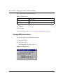
Viewing MDA information . . . . . . . . . . . . . . . . . . . . . . . . . . . . . . . . . . . . . . . . . . . 52
Command line interface . . . . . . . . . . . . . . . . . . . . . . . . . . . . . . . . . . . . . . . . . . . . . . . . 53
Configuration procedures . . . . . . . . . . . . . . . . . . . . . . . . . . . . . . . . . . . . . . . . . . . . . . . 54
Default configurations . . . . . . . . . . . . . . . . . . . . . . . . . . . . . . . . . . . . . . . . . . . . . . 54
Basic procedures . . . . . . . . . . . . . . . . . . . . . . . . . . . . . . . . . . . . . . . . . . . . . . . . . . 55
Enabling or disabling a port . . . . . . . . . . . . . . . . . . . . . . . . . . . . . . . . . . . . . . . . . . 59
SONET parameters . . . . . . . . . . . . . . . . . . . . . . . . . . . . . . . . . . . . . . . . . . . . . . . . . . . 59
Configuring bridging . . . . . . . . . . . . . . . . . . . . . . . . . . . . . . . . . . . . . . . . . . . . . . . 62
Configuring routing . . . . . . . . . . . . . . . . . . . . . . . . . . . . . . . . . . . . . . . . . . . . . . . . 63
Configuring IP routing using Device Manager . . . . . . . . . . . . . . . . . . . . . . . . . 63
Configuring IP routing using the CLI . . . . . . . . . . . . . . . . . . . . . . . . . . . . . . . . 67
Configuring IPX routing using Device Manager . . . . . . . . . . . . . . . . . . . . . . . 68
Configuring IPX routing using the CLI . . . . . . . . . . . . . . . . . . . . . . . . . . . . . . . 71
Trap feature . . . . . . . . . . . . . . . . . . . . . . . . . . . . . . . . . . . . . . . . . . . . . . . . . . . . . . . . . 71
Viewing the Trap Log . . . . . . . . . . . . . . . . . . . . . . . . . . . . . . . . . . . . . . . . . . . . . . . . . . 74
SONET loopback test feature . . . . . . . . . . . . . . . . . . . . . . . . . . . . . . . . . . . . . . . . . . . 75
Alarms . . . . . . . . . . . . . . . . . . . . . . . . . . . . . . . . . . . . . . . . . . . . . . . . . . . . . . . . . . . . . 77
209564-A
Contents
9
Chapter 5
Graphing statistics in Device Manager . . . . . . . . . . . . . . . . . . . . . . . . . . . . 79
Overview . . . . . . . . . . . . . . . . . . . . . . . . . . . . . . . . . . . . . . . . . . . . . . . . . . . . . . . . . . . 79
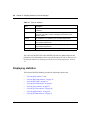
Displaying statistics . . . . . . . . . . . . . . . . . . . . . . . . . . . . . . . . . . . . . . . . . . . . . . . . . . . 80
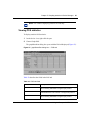
Viewing POS statistics . . . . . . . . . . . . . . . . . . . . . . . . . . . . . . . . . . . . . . . . . . . . . . 81
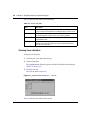
Viewing PPP Link statistics . . . . . . . . . . . . . . . . . . . . . . . . . . . . . . . . . . . . . . . . . . 82
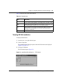
Viewing PPP LQR . . . . . . . . . . . . . . . . . . . . . . . . . . . . . . . . . . . . . . . . . . . . . . . . . 84
Viewing Section statistics . . . . . . . . . . . . . . . . . . . . . . . . . . . . . . . . . . . . . . . . . . . 85
Viewing Line statistics . . . . . . . . . . . . . . . . . . . . . . . . . . . . . . . . . . . . . . . . . . . . . . 86
Viewing FE Line statistics . . . . . . . . . . . . . . . . . . . . . . . . . . . . . . . . . . . . . . . . . . . 87
Viewing Path statistics . . . . . . . . . . . . . . . . . . . . . . . . . . . . . . . . . . . . . . . . . . . . . . 88
Viewing FE Path statistics . . . . . . . . . . . . . . . . . . . . . . . . . . . . . . . . . . . . . . . . . . . 89
Chapter 6
Command line interface . . . . . . . . . . . . . . . . . . . . . . . . . . . . . . . . . . . . . . . . 91
Configuration commands . . . . . . . . . . . . . . . . . . . . . . . . . . . . . . . . . . . . . . . . . . . . . . . 92
config poscard commands . . . . . . . . . . . . . . . . . . . . . . . . . . . . . . . . . . . . . . . . . . . 92
Port commands . . . . . . . . . . . . . . . . . . . . . . . . . . . . . . . . . . . . . . . . . . . . . . . . . . . 93
config pos command . . . . . . . . . . . . . . . . . . . . . . . . . . . . . . . . . . . . . . . . . . . . . . . 93
config pos ip . . . . . . . . . . . . . . . . . . . . . . . . . . . . . . . . . . . . . . . . . . . . . . . . . . 94
config pos ppp . . . . . . . . . . . . . . . . . . . . . . . . . . . . . . . . . . . . . . . . . . . . . . . . . 95
config pos sonet command . . . . . . . . . . . . . . . . . . . . . . . . . . . . . . . . . . . . . . . 96
config pos stg command . . . . . . . . . . . . . . . . . . . . . . . . . . . . . . . . . . . . . . . . . 97
config pos info command . . . . . . . . . . . . . . . . . . . . . . . . . . . . . . . . . . . . . . . . . . . . 98
Show commands . . . . . . . . . . . . . . . . . . . . . . . . . . . . . . . . . . . . . . . . . . . . . . . . . . . . . 99
show ports info pos . . . . . . . . . . . . . . . . . . . . . . . . . . . . . . . . . . . . . . . . . . . . . . . 100
show ports info pos all . . . . . . . . . . . . . . . . . . . . . . . . . . . . . . . . . . . . . . . . . . 100
show ports stats pos activealarms . . . . . . . . . . . . . . . . . . . . . . . . . . . . . . . . . . . . 104
show ports stats pos felinecurrent . . . . . . . . . . . . . . . . . . . . . . . . . . . . . . . . . . . . 105
show ports stats pos felineinterval . . . . . . . . . . . . . . . . . . . . . . . . . . . . . . . . . . . . 107
show ports stats pos fepathcurrent . . . . . . . . . . . . . . . . . . . . . . . . . . . . . . . . . . . 108
show ports stats pos fepathinterval . . . . . . . . . . . . . . . . . . . . . . . . . . . . . . . . . . . 109
show ports stats pos linecurrent . . . . . . . . . . . . . . . . . . . . . . . . . . . . . . . . . . . . . 111
show ports stats pos lineinterval . . . . . . . . . . . . . . . . . . . . . . . . . . . . . . . . . . . . . 112
show ports stats pos linkstatus . . . . . . . . . . . . . . . . . . . . . . . . . . . . . . . . . . . . . . 114
Using the Passport 8683POS Module
10
Contents
show ports stats pos lqrstatus . . . . . . . . . . . . . . . . . . . . . . . . . . . . . . . . . . . . . . . 115
show ports stats pos pathcurrent . . . . . . . . . . . . . . . . . . . . . . . . . . . . . . . . . . . . . 116
show ports stats pos pathinterval . . . . . . . . . . . . . . . . . . . . . . . . . . . . . . . . . . . . 117
show ports stats pos pppiftbl . . . . . . . . . . . . . . . . . . . . . . . . . . . . . . . . . . . . . . . . 118
show ports stats pos sectioncurrent . . . . . . . . . . . . . . . . . . . . . . . . . . . . . . . . . . 120
show ports stats pos sectioninterval . . . . . . . . . . . . . . . . . . . . . . . . . . . . . . . . . . 121
show ports stats pos sonetmediumtbl . . . . . . . . . . . . . . . . . . . . . . . . . . . . . . . . . 123
show tech command . . . . . . . . . . . . . . . . . . . . . . . . . . . . . . . . . . . . . . . . . . . . . . 124
Monitor commands . . . . . . . . . . . . . . . . . . . . . . . . . . . . . . . . . . . . . . . . . . . . . . . . . . . 126
Test commands . . . . . . . . . . . . . . . . . . . . . . . . . . . . . . . . . . . . . . . . . . . . . . . . . . . . . 127
Using the test commands . . . . . . . . . . . . . . . . . . . . . . . . . . . . . . . . . . . . . . . . . . 128
test hardware . . . . . . . . . . . . . . . . . . . . . . . . . . . . . . . . . . . . . . . . . . . . . . . . . . . . 128
test led . . . . . . . . . . . . . . . . . . . . . . . . . . . . . . . . . . . . . . . . . . . . . . . . . . . . . . . . . 128
test loopback . . . . . . . . . . . . . . . . . . . . . . . . . . . . . . . . . . . . . . . . . . . . . . . . . . . . 129
Chapter 7
Web management . . . . . . . . . . . . . . . . . . . . . . . . . . . . . . . . . . . . . . . . . . . . 131
POS folder . . . . . . . . . . . . . . . . . . . . . . . . . . . . . . . . . . . . . . . . . . . . . . . . . . . . . . . . . 131
Statistics . . . . . . . . . . . . . . . . . . . . . . . . . . . . . . . . . . . . . . . . . . . . . . . . . . . . . . . . . . . 143
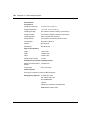
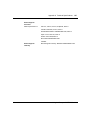
Appendix A
Technical Specifications . . . . . . . . . . . . . . . . . . . . . . . . . . . . . . . . . . . . . . . 145
Index . . . . . . . . . . . . . . . . . . . . . . . . . . . . . . . . . . . . . . . . . . . . . . . . . . . . . . . 149
209564-A
11
Figures
Figure 1
Passport 8683POS Module . . . . . . . . . . . . . . . . . . . . . . . . . . . . . . . . . . . 25
Figure 2
1-port OC-12c/STM-4 MDA . . . . . . . . . . . . . . . . . . . . . . . . . . . . . . . . . . . 26
Figure 3
2-port OC-3c/STM-1 MDA . . . . . . . . . . . . . . . . . . . . . . . . . . . . . . . . . . . . 26
Figure 4
Passport 868POS module with an OC-12c/STM-4 MDA . . . . . . . . . . . . . 27
Figure 5
Removing the filler panel . . . . . . . . . . . . . . . . . . . . . . . . . . . . . . . . . . . . . 37
Figure 6
Extending the inserter/extractor levers . . . . . . . . . . . . . . . . . . . . . . . . . . . 38
Figure 7
Inserting the Passport 8683POS Module . . . . . . . . . . . . . . . . . . . . . . . . . 38
Figure 8
Closing the inserter/extractor levers . . . . . . . . . . . . . . . . . . . . . . . . . . . . . 39
Figure 9
Tightening the retainer screws . . . . . . . . . . . . . . . . . . . . . . . . . . . . . . . . . 39
Figure 10
Passport 8600 series chassis with Passport 8683POS Module . . . . . . . . 48
Figure 11
Card tab . . . . . . . . . . . . . . . . . . . . . . . . . . . . . . . . . . . . . . . . . . . . . . . . . . 50
Figure 12
POS tab . . . . . . . . . . . . . . . . . . . . . . . . . . . . . . . . . . . . . . . . . . . . . . . . . . 51
Figure 13
MDA dialog box . . . . . . . . . . . . . . . . . . . . . . . . . . . . . . . . . . . . . . . . . . . . 52
Figure 14
Port dialog box — Interface tab . . . . . . . . . . . . . . . . . . . . . . . . . . . . . . . . 56
Figure 15
Port dialog box — POS SONET tab . . . . . . . . . . . . . . . . . . . . . . . . . . . . . 60
Figure 16
Port dialog box — POS PPP tab . . . . . . . . . . . . . . . . . . . . . . . . . . . . . . . 64
Figure 17
Port dialog box — IP Address tab . . . . . . . . . . . . . . . . . . . . . . . . . . . . . . 66
Figure 18
Port, Insert IP Address dialog box . . . . . . . . . . . . . . . . . . . . . . . . . . . . . . 67
Figure 19
VLAN dialog box — Basic tab . . . . . . . . . . . . . . . . . . . . . . . . . . . . . . . . . 69
Figure 20
Chassis dialog box — System tab . . . . . . . . . . . . . . . . . . . . . . . . . . . . . . 72
Figure 21
Chassis dialog box — Trap Receivers tab . . . . . . . . . . . . . . . . . . . . . . . . 72
Figure 22
Chassis, Insert Trap Receiver dialog box . . . . . . . . . . . . . . . . . . . . . . . . . 73
Figure 23
Trap Log dialog box . . . . . . . . . . . . . . . . . . . . . . . . . . . . . . . . . . . . . . . . . 74
Figure 24
Port dialog box — Test tab . . . . . . . . . . . . . . . . . . . . . . . . . . . . . . . . . . . . 75
Figure 25
graphSonetPort dialog box — POS tab . . . . . . . . . . . . . . . . . . . . . . . . . . 81
Figure 26
graphSonetPort dialog box — PPP Link tab . . . . . . . . . . . . . . . . . . . . . . . 83
Figure 27
graphSonetPort dialog box — PPP LQR tab . . . . . . . . . . . . . . . . . . . . . . 84
Figure 28
graphSonetPort dialog box — Section tab . . . . . . . . . . . . . . . . . . . . . . . . 85
Figure 29
graphSonetPort dialog box — Line tab . . . . . . . . . . . . . . . . . . . . . . . . . . . 86
Figure 30
graphSonetPort dialog box — FE Line tab . . . . . . . . . . . . . . . . . . . . . . . . 87
Using the Passport 8683POS Module
12
Figures
Figure 31
graphSonetPort dialog box — Path tab . . . . . . . . . . . . . . . . . . . . . . . . . . 88
Figure 32
graphSonetPort dialog box — FE Path tab . . . . . . . . . . . . . . . . . . . . . . . 89
Figure 33
config pos info command sample output . . . . . . . . . . . . . . . . . . . . . . . . . 98
Figure 34
show ports info pos all command output . . . . . . . . . . . . . . . . . . . . . . . . 101
Figure 35
show ports info pos all command output (continued)
Figure 36
show ports stats pos activealarms command output . . . . . . . . . . . . . . . 105
Figure 37
show ports stats pos felinecurrent command output . . . . . . . . . . . . . . . 106
Figure 38
show ports stats pos felineinterval command output . . . . . . . . . . . . . . . 107
Figure 39
show ports stats pos fepathcurrent command output . . . . . . . . . . . . . . . 108
Figure 40
show ports stats pos fepathinterval command output . . . . . . . . . . . . . . . 110
Figure 41
show ports stats pos linecurrent command output . . . . . . . . . . . . . . . . . 111
Figure 42
show ports stats pos lineinterval command output . . . . . . . . . . . . . . . . . 113
Figure 43
show ports stats pos linkstatus command output . . . . . . . . . . . . . . . . . 114
. . . . . . . . . . . . . . 102
Figure 44
show ports stats pos lqrstatus command output . . . . . . . . . . . . . . . . . . . 115
Figure 45
show ports stats pos pathcurrent command output . . . . . . . . . . . . . . . . 116
Figure 46
show ports stats pos pathinterval command output . . . . . . . . . . . . . . . . 117
Figure 47
show ports stats pos pppiftbl command output . . . . . . . . . . . . . . . . . . . 119
Figure 48
show ports stats pos sectioncurrent command output . . . . . . . . . . . . . . 120
Figure 49
show ports stats pos sectioninterval command output . . . . . . . . . . . . . . 122
Figure 50
show ports stats pos sonetmediumtbl command output . . . . . . . . . . . . . 123
Figure 51
show tech command output . . . . . . . . . . . . . . . . . . . . . . . . . . . . . . . . . . 125
Figure 52
test hardware command output . . . . . . . . . . . . . . . . . . . . . . . . . . . . . . . 128
Figure 53
test loopback command output . . . . . . . . . . . . . . . . . . . . . . . . . . . . . . . . 130
Figure 54
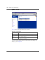
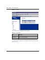
System page . . . . . . . . . . . . . . . . . . . . . . . . . . . . . . . . . . . . . . . . . . . . . . 132
Figure 55
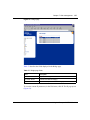
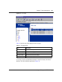
System page showing the POS menu . . . . . . . . . . . . . . . . . . . . . . . . . . 134
Figure 56
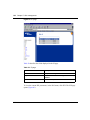
SONET page . . . . . . . . . . . . . . . . . . . . . . . . . . . . . . . . . . . . . . . . . . . . . 135
Figure 57
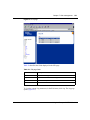
Link page . . . . . . . . . . . . . . . . . . . . . . . . . . . . . . . . . . . . . . . . . . . . . . . . 136
Figure 58
Bridge page . . . . . . . . . . . . . . . . . . . . . . . . . . . . . . . . . . . . . . . . . . . . . . 137
Figure 59
IP page . . . . . . . . . . . . . . . . . . . . . . . . . . . . . . . . . . . . . . . . . . . . . . . . . . 138
Figure 60
IPX page . . . . . . . . . . . . . . . . . . . . . . . . . . . . . . . . . . . . . . . . . . . . . . . . . 139
Figure 61
Lqr page . . . . . . . . . . . . . . . . . . . . . . . . . . . . . . . . . . . . . . . . . . . . . . . . . 140
Figure 62
Line page . . . . . . . . . . . . . . . . . . . . . . . . . . . . . . . . . . . . . . . . . . . . . . . . 141
Figure 63
SONET Medium page . . . . . . . . . . . . . . . . . . . . . . . . . . . . . . . . . . . . . . 142
Figure 64
Sonet options . . . . . . . . . . . . . . . . . . . . . . . . . . . . . . . . . . . . . . . . . . . . . 143
Figure 65
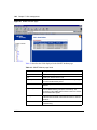
PPP Link statistics page . . . . . . . . . . . . . . . . . . . . . . . . . . . . . . . . . . . . . 144
209564-A
13
Tables
Table 1
Passport 8683POS Module online LED indications . . . . . . . . . . . . . . . . . 27
Table 2
MDA LED indications . . . . . . . . . . . . . . . . . . . . . . . . . . . . . . . . . . . . . . . . 28
Table 3
Passport 8683POS Module access levels . . . . . . . . . . . . . . . . . . . . . . . . 47
Table 4
Passport Device Manager port color codes . . . . . . . . . . . . . . . . . . . . . . . 49
Table 5
Passport Device Manager buttons . . . . . . . . . . . . . . . . . . . . . . . . . . . . . . 49
Table 6
Card tab fields . . . . . . . . . . . . . . . . . . . . . . . . . . . . . . . . . . . . . . . . . . . . . 51
Table 7
POS tab fields . . . . . . . . . . . . . . . . . . . . . . . . . . . . . . . . . . . . . . . . . . . . . . 52
Table 8
MDA dialog box fields . . . . . . . . . . . . . . . . . . . . . . . . . . . . . . . . . . . . . . . . 53
Table 9
Passport 8683POS Module default settings . . . . . . . . . . . . . . . . . . . . . . 54
Table 10
Interface tab items . . . . . . . . . . . . . . . . . . . . . . . . . . . . . . . . . . . . . . . . . . 57
Table 11
POS SONET tab items . . . . . . . . . . . . . . . . . . . . . . . . . . . . . . . . . . . . . . . 61
Table 12
POS PPP tab items . . . . . . . . . . . . . . . . . . . . . . . . . . . . . . . . . . . . . . . . . 65
Table 13
IP Address tab fields . . . . . . . . . . . . . . . . . . . . . . . . . . . . . . . . . . . . . . . . . 66
Table 14
Insert IP Address dialog box items . . . . . . . . . . . . . . . . . . . . . . . . . . . . . . 67
Table 15
Basic tab fields . . . . . . . . . . . . . . . . . . . . . . . . . . . . . . . . . . . . . . . . . . . . . 69
Table 16
Trap Receivers tab fields . . . . . . . . . . . . . . . . . . . . . . . . . . . . . . . . . . . . . 73
Table 17
Insert Trap Receiver dialog box fields . . . . . . . . . . . . . . . . . . . . . . . . . . . 73
Table 18
Trap Log dialog box fields . . . . . . . . . . . . . . . . . . . . . . . . . . . . . . . . . . . . . 74
Table 19
Test tab items . . . . . . . . . . . . . . . . . . . . . . . . . . . . . . . . . . . . . . . . . . . . . . 76
Table 20
Passport 8683POS Module alarms . . . . . . . . . . . . . . . . . . . . . . . . . . . . . 77
Table 21
Types of statistics . . . . . . . . . . . . . . . . . . . . . . . . . . . . . . . . . . . . . . . . . . . 80
Table 22
POS tab fields . . . . . . . . . . . . . . . . . . . . . . . . . . . . . . . . . . . . . . . . . . . . . 81
Table 23
PPP Link tab fields . . . . . . . . . . . . . . . . . . . . . . . . . . . . . . . . . . . . . . . . . . 83
Table 24
PPP LQR tab fields . . . . . . . . . . . . . . . . . . . . . . . . . . . . . . . . . . . . . . . . . . 85
Table 25
Section tab fields . . . . . . . . . . . . . . . . . . . . . . . . . . . . . . . . . . . . . . . . . . . 86
Table 26
Line tab fields . . . . . . . . . . . . . . . . . . . . . . . . . . . . . . . . . . . . . . . . . . . . . . 87
Table 27
FE Line tab fields . . . . . . . . . . . . . . . . . . . . . . . . . . . . . . . . . . . . . . . . . . . 88
Table 28
Path tab fields . . . . . . . . . . . . . . . . . . . . . . . . . . . . . . . . . . . . . . . . . . . . . 89
Table 29
FE Path tab fields . . . . . . . . . . . . . . . . . . . . . . . . . . . . . . . . . . . . . . . . . . . 90
Using the Passport 8683POS Module
14
Tables
Table 30
config poscard command parameters and variables . . . . . . . . . . . . . . . . 93
Table 31
config pos command parameters and variables . . . . . . . . . . . . . . . . . . . . 94
Table 32
config pos ip command parameters and variables . . . . . . . . . . . . . . . . . 95
Table 33
config pos ppp command parameters and variables . . . . . . . . . . . . . . . . 96
Table 34
config pos sonet command parameters and variables . . . . . . . . . . . . . . . 97
Table 35
config pos stg command parameters and variables . . . . . . . . . . . . . . . . . 98
Table 36
Information fields for output of the show ports info pos
all command . . . . . . . . . . . . . . . . . . . . . . . . . . . . . . . . . . . . . . . . . . . . . 103
Table 37
Information fields for output of the show ports stats pos
activealarms command . . . . . . . . . . . . . . . . . . . . . . . . . . . . . . . . . . . . . . 105
Table 38
Information fields for output of the show ports stats pos
felinecurrent command . . . . . . . . . . . . . . . . . . . . . . . . . . . . . . . . . . . . . . 106
Table 39
Information fields for output of the show ports stats pos
felineinterval command . . . . . . . . . . . . . . . . . . . . . . . . . . . . . . . . . . . . . . 108
Table 40
Information fields for output of the show ports stats pos
fepathcurrent command . . . . . . . . . . . . . . . . . . . . . . . . . . . . . . . . . . . . . 109
Table 41
Information fields for output of the show ports stats pos
fepathinterval command . . . . . . . . . . . . . . . . . . . . . . . . . . . . . . . . . . . . . 110
Table 42
Information fields for output of the show ports stats pos
linecurrent command . . . . . . . . . . . . . . . . . . . . . . . . . . . . . . . . . . . . . . . 112
Table 43
Information fields for output of the show ports stats pos
lineinterval command . . . . . . . . . . . . . . . . . . . . . . . . . . . . . . . . . . . . . . . 113
Table 44
Information fields for output of the show ports stats pos
linkstatus command . . . . . . . . . . . . . . . . . . . . . . . . . . . . . . . . . . . . . . . . 114
Table 45
Information fields for output of the show ports stats pos
lqrstatus command . . . . . . . . . . . . . . . . . . . . . . . . . . . . . . . . . . . . . . . . . 115
Table 46
Information fields for output of the show ports stats pos
pathcurrent command . . . . . . . . . . . . . . . . . . . . . . . . . . . . . . . . . . . . . . . 117
Table 47
Information fields for output of the show ports stats pos
pathinterval command . . . . . . . . . . . . . . . . . . . . . . . . . . . . . . . . . . . . . . 118
Table 48
Information fields for output of the show ports stats pos
pppiftbl command . . . . . . . . . . . . . . . . . . . . . . . . . . . . . . . . . . . . . . . . . . 119
Table 49
Information fields for output of the show ports stats pos
sectioncurrent command . . . . . . . . . . . . . . . . . . . . . . . . . . . . . . . . . . . . 121
Table 50
Information fields for output of the show ports stats pos
sectioninterval command . . . . . . . . . . . . . . . . . . . . . . . . . . . . . . . . . . . . 122
Table 51
Information fields for output of the show ports stats pos
sonetmediumtbl command . . . . . . . . . . . . . . . . . . . . . . . . . . . . . . . . . . . 124
209564-A
Tables
15
Table 52
Information fields for output of the show tech command . . . . . . . . . . . . 126
Table 53
test led command parameters and variables . . . . . . . . . . . . . . . . . . . . . 129
Table 54
System page fields . . . . . . . . . . . . . . . . . . . . . . . . . . . . . . . . . . . . . . . . . 133
Table 55
SONET page fields . . . . . . . . . . . . . . . . . . . . . . . . . . . . . . . . . . . . . . . . . 135
Table 56
Link page fields . . . . . . . . . . . . . . . . . . . . . . . . . . . . . . . . . . . . . . . . . . . . 136
Table 57
Bridge page fields . . . . . . . . . . . . . . . . . . . . . . . . . . . . . . . . . . . . . . . . . . 137
Table 58
IP page . . . . . . . . . . . . . . . . . . . . . . . . . . . . . . . . . . . . . . . . . . . . . . . . . . 138
Table 59
IPX page fields . . . . . . . . . . . . . . . . . . . . . . . . . . . . . . . . . . . . . . . . . . . . 139
Table 60
Lqr page fields . . . . . . . . . . . . . . . . . . . . . . . . . . . . . . . . . . . . . . . . . . . . 140
Table 61
Line page fields . . . . . . . . . . . . . . . . . . . . . . . . . . . . . . . . . . . . . . . . . . . 141
Table 62
SONET Medium page fields . . . . . . . . . . . . . . . . . . . . . . . . . . . . . . . . . . 142
Using the Passport 8683POS Module
16
Tables
209564-A
17
Preface
The Passport® 8683POS Module is part of the Nortel Networks Passport® 8600
Series line of communications products. This module is the Passport Packet over
SONET (POS) module for the Passport 8600 chassis. This guide describes the
features and operations of the Passport 8683POS Module and provides
instructions for installing and managing the module.
Before you begin
This guide is intended for network installers and system administrators who are
responsible for installing, configuring, or maintaining networks. This guide
assumes that you have the following background:
•
•
Understanding of the transmission and management protocols used on your
network
Experience with windowing systems or graphical user interfaces (GUIs)
Using the Passport 8683POS Module
18
Preface
Text conventions
This guide uses the following text conventions:
angle brackets (< >)
Indicate that you choose the text to enter based on the
description inside the brackets. Do not type the
brackets when entering the command.
Example: If the command syntax is
ping <ip_address>, you enter
ping 192.32.10.12
bold Courier text
Indicates command names and options and text that
you need to enter.
Example: Use the dinfo command.
Example: Enter show ip {alerts|routes}.
braces ({})
Indicate required elements in syntax descriptions where
there is more than one option. You must choose only
one of the options. Do not type the braces when
entering the command.
Example: If the command syntax is
show ip {alerts|routes}, you must enter either
show ip alerts or show ip routes, but not both.
brackets ([ ])
Indicate optional elements in syntax descriptions. Do
not type the brackets when entering the command.
Example: If the command syntax is
show ip interfaces [-alerts], you can enter
either show ip interfaces or
show ip interfaces -alerts.
ellipsis points (. . . )
Indicate that you repeat the last element of the
command as needed.
Example: If the command syntax is
ethernet/2/1 [<parameter> <value>]... ,
you enter ethernet/2/1 and as many
parameter-value pairs as needed.
209564-A
Preface
19
italic text
Indicates new terms, book titles, and variables in
command syntax descriptions. Where a variable is two
or more words, the words are connected by an
underscore.
Example: If the command syntax is
show at <valid_route>, valid_route is one
variable and you substitute one value for it.
plain Courier
text
Indicates command syntax and system output, for
example, prompts and system messages.
Example: Set Trap Monitor Filters
separator ( > )
Shows menu paths.
Example: Protocols > IP identifies the IP command on
the Protocols menu.
vertical line ( | )
Separates choices for command keywords and
arguments. Enter only one of the choices. Do not type
the vertical line when entering the command.
Example: If the command syntax is
show ip {alerts|routes}, you enter either
show ip alerts or show ip routes, but not
both.
Using the Passport 8683POS Module
20
Preface
Related publications
For more information about Passport 8600 series products and management
software, refer to the following publications:
•
•
•
•
•
•
•
•
•
•
•
Installing the Passport 8683POS Module MDAs (part number 209565-A)
Getting Started with the Passport 8000 Series Management Software
(part number 209663-C)
Using the Passport 8600 Modules (part number 207306-C)
Installation Instructions for the Passport 8600 Modules
(part number 207372-C)
Networking Concepts for the Passport 8000 Series Switch
(part number 207307-C)
Passport 8000 Series Network Design Guidelines, Release 3.0
Implementation Notes (part number 210128-A)
Reference for the Passport 8000 Series Command Line Interface Switching
Operations Release 3.1 (part number 207308-D)
Reference for the Passport 8000 Series Command Line Interface Routing
Operations Release 3.1 (part number 208967-C)
Reference for the Passport 8000 Series Management Software Switching
Operations Release 3.1 (part number 207414-D)
Reference for the Passport 8000 Series Management Software Routing
Operations Release 3.1 (part number 207415-C)
Release Notes for the Passport 8000 Series Switch (part number 211014-A)
You can print selected technical manuals and release notes free, directly from the
Internet. Go to the www25.nortelnetworks.com/library/tpubs/ URL. Find the
product for which you need documentation. Then locate the specific category and
model or version for your hardware or software product. Use Adobe Acrobat
Reader to open the manuals and release notes, search for the sections you need,
and print them on most standard printers. Go to Adobe Systems at the
www.adobe.com URL to download a free copy of the Adobe Acrobat Reader.
You can purchase selected documentation sets, CDs, and technical publications
through the Internet at the www1.fatbrain.com/documentation/nortel/ URL.
209564-A
Preface
21
How to get help
If you purchased a service contract for your Nortel Networks product from a
distributor or authorized reseller, contact the technical support staff for that
distributor or reseller for assistance.
If you purchased a Nortel Networks service program, contact one of the following
Nortel Networks Technical Solutions Centers:
Technical Solutions Center
Telephone
EMEA
(33) (4) 92-966-968
North America
(800) 2LANWAN or (800) 252-6926
Asia Pacific
(61) (2) 9927-8800
China
(800) 810-5000
An Express Routing Code (ERC) is available for many Nortel Networks products
and services. When you use an ERC, your call is routed to a technical support
person who specializes in supporting that product or service. To locate an ERC for
your product or service, go to the www12.nortelnetworks.com/ URL and click
ERC at the bottom of the page.
Using the Passport 8683POS Module
22
Preface
209564-A
23
Chapter 1
About the Passport 8683POS Module
The Passport 8683POS Module provides network transmission using packet over
Synchronous Optical Network (SONET) services. The Passport 8683POS Module
for the Passport 8600 series routing switches provides WAN support to the
Passport product line by allowing access to SONET services in the metropolitan
area. Where multiple campuses exist in a single metropolitan area, you can
connect these campuses without compromising performance or increasing
complexity.
The Passport 8683POS Module is a baseboard with slots for three of the following
two optional media dependent adapters (MDAs):
•
•
1-port OC-12c/STM-4: single-mode fiber (SMF) or multimode fiber (MMF)
using SONET/SDH
2-port OC-3c/STM-1: SMF or MMF using SONET/SDH
The Passport 8683POS Module supports up to six input/output (I/O) OC-3c/
STM-1 lines and up to three I/O OC-12 lines. You can mix these MDAs on a
single Passport 8683POS Module. For example, you can put an OC-12 MDA into
the first slot and OC-3 MDAs into the two remaining slots. For information on OC
lines, PPP, and SONET, refer to Chapter 2, “Using the Passport 8683POS
Module,” on page 29.
You can put more than one Passport 8683POS Module in the Passport 8600 series
chassis, except slots 5 and 6, which are reserved for the Passport 8690 Switch
Fabric (SF) modules. The maximum number of modules on a chassis is four.
One Passport 8690 SF module acts as the CPU for the chassis, and the other
module is the standby CPU, taking over in case of failure. If a CPU failover
occurs, all traffic on the chassis stops momentarily while the standby CPU
reinitializes all input/output modules.
Using the Passport 8683POS Module
24
Chapter 1 About the Passport 8683POS Module
Refer to Networking Concepts for the Passport 8000 Series Switch, Release 3.1
for a thorough discussion of the complete functionality of the Passport product
line, including the Passport 8683POS Module.
This chapter provides the following information about the Passport 8683POS
Module:
•
•
“Features,” next
“Physical description” on page 25
Features
The Passport 8683POS Module has the following features:
•
•
•
•
•
•
•
•
•
•
•
•
•
•
•
209564-A
SONET and SDH compliant, supporting OC-3c/STM-1 and OC-12c/STM-4
framing
Front-panel LEDs to monitor port activity and module operation
Ability to remove and install a module (hot-swap) without resetting the switch
MTBF of 150,000 hours
Internal and external loopback support on all ports for testing purposes
Hardware diagnostics
Brouter port configuration
Bridging support: RFC 1638-compliant
Routing support for both unicast and multicast IP and IPX routing
Support for both single-mode fiber (SMF) and multimode fiber (MMF)
cabling
Support for DVMRP
Support for IGMP
Support for MultiLink Trunking (MLT)
Support for the following VLAN features currently implemented in the
Passport switches including:
— Port-based VLAN
— Policy-based VLANs (protocol-based, IP subnet-based VLANs)
— IEEE 802.1Q tagged VLANs
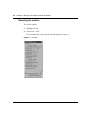
Support for the following RFCs:
Chapter 1 About the Passport 8683POS Module
•
•
•
25
— PPP over SONET: RFC 2615
— SONET/SDH: RFC 2558
— PPP: RFC 1471, RFC 1473, RFC 1474, and RFC 1661
— LQM: RFC 1989
— SNMP: RFC 1213
— IPCP: RFC 1332
— IPXCP: RFC1552
— BCP: RFC 1638_
Multiple spanning tree groups - bridge mode only
Manageable through the Passport CLI or Device Manager, the SNMP-based
graphical user interface
Monitored through a World Wide Web browser from anywhere on the
network
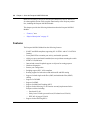
Physical description
The Passport 8683POS Module (Figure 1) is a single-slot module for the Passport
8600 series chassis. Online LEDs indicate module operation.
Figure 1 Passport 8683POS Module
Diag Port Link
Console
8683POS
MDA1
MDA 2
MDA 3
Online
9904 B
To configure and manage the Passport 8683POS Module, connect to the Passport
8690 SF module. For information on connecting to the Passport 8690 SF console
port, refer to Using the Passport 8600 Modules.
Using the Passport 8683POS Module
26
Chapter 1 About the Passport 8683POS Module
Media dependent adapters
The Passport 8683POS Module has slots for three media dependent adapters
(MDAs) that have their own LEDs. You can use up to three of the following
MDAs with the Passport 8683POS Module:
•
•
1-port OC-12c/STM-4: SMF or MMF using SONET/SDH
2-port OC-3c/STM-1: SMF or MMF using SONET/SDH
You can mix these MDAs on the Passport 8683POS Module.
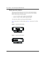
Figure 2 shows the OC-12c/STM-4 MDA, and Figure 3 shows the OC-3c/STM-1
MDA.
Figure 2 1-port OC-12c/STM-4 MDA
9902EB
Figure 3 2-port OC-3c/STM-1 MDA
9903EB
209564-A
Chapter 1 About the Passport 8683POS Module
27
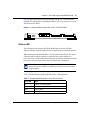
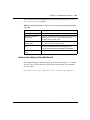
Figure 4 shows the Passport 8683POS Module with the OC-12c/STM-4 MDA
installed. (For information on installing the MDAs, refer to Installing the Passport
8683POS Module MDAs.
Figure 4 Passport 868POS module with an OC-12c/STM-4 MDA
Diag Port Link
Console
8683POS
MDA1
MDA 2
MDA 3
Online
10040EA
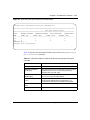
Online LED
The front panel of the Passport 8683POS Module has an Online LED that
indicates whether or not the module has power applied and is initialized correctly.
When the Passport 8683POS Module is first inserted into the chassis, the Online
LED turns amber until the board is recognized by the system and passes a
power-on self-test. If the module fails the self-test, the light is off. When the board
passes the self-test and goes online, the LED illuminates a solid green.
Note: You cannot configure the Passport 8683POS Module until the
online LED on the module is steadily lit green and you have inserted at
least one MDA.
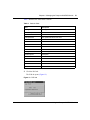
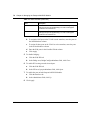
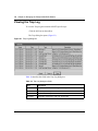
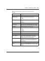
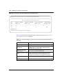
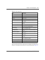
Table 1 lists the Passport 8683POS Module online LED indications.
Table 1 Passport 8683POS Module online LED indications
Online LED
State
Off
Card is not receiving power.
Amber
Card is initializing or downloading.
Amber
Card is offline.
Green
Card is online.
Using the Passport 8683POS Module
28
Chapter 1 About the Passport 8683POS Module
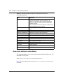
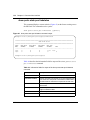
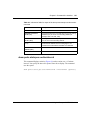
MDA LEDs
Table 2 lists the MDA LED indications.
Table 2 MDA LED indications
Tx LED
Rx LED
Port State
Amber
Amber
AdminDown/Out-of-Service
Off
Amber
AdminUp/In-Service/Sonet-alarm-condition
Amber
Green
AdminUp/In-Service/Sonet-Up/PPP link
down
Off
Green
AdminUp/In-Service/Sonet-Up/PPP-UP
Green (Blinking)
Green (Blinking)
Admin Up/In-Service/Traffic Activity
Console and Diag ports
Use the Console port on the Passport 8690 SF module to access management
functions for the Passport 8683POS Module. For information on connecting to the
console port on the Passport 8690 SF module, refer to Getting Started with the
Passport 8000 Series Management Software.
The Diag port on the Passport 8683POS Module is used only by Nortel Networks
personnel for debugging purposes. You can see diagnostic messages but you
cannot input any text.
The Diag port on the module is an RJ-45 port that allows out-of-band
management by Nortel Networks personnel.
209564-A
29
Chapter 2
Using the Passport 8683POS Module
A typical application consists of a single Passport 8683POS Module in an
Passport 8600 series switch, but multiple modules are also supported. This chapter
briefly explains how the Passport 8683POS Module operates within the Passport
switch.
A typical network application of the Passport 8683POS Module is a direct
connection between one Passport 8600 series switch with a Passport 8683POS
Module in one campus to an identical module in another Passport 8600 series
switch at another campus connected over a SONET ring. Using this connection,
you achieve an intercampus link through packet over SONET (POS) technology.
This chapter contains the following information:
•
•
“SONET transmission,” next
“Spanning tree group feature” on page 33
SONET transmission
You can connect the Passport 8683POS Module through a Synchronous Optical
Network (SONET) termination multiplexor to extend the range of the wide area
network (WAN) connections. Or, you can connect the Passport 8683POS Module,
using fiber, directly to a POS interface on another Passport routing switch or on a
traditional router.
The SONET frames received from the WAN contain IP packets encapsulated in
Point-to-Point Protocol (PPP) that are converted by the Passport 8683POS
Module into an Ethernet format. Similarly, the Passport 8683POS Module
receives Ethernet frames and converts them into PPP packets for transmission
over SONET.
Using the Passport 8683POS Module
30
Chapter 2 Using the Passport 8683POS Module
SONET terms and acronyms
This section provides a brief listing of common Synchronous Optical Network
(SONET) terms. SONET is a medium for transmitting data that uses fiber-optic
cables.
The following terms and acronyms are frequently used with SONET information:
•
•
•
•
•
•
SONET: Synchronous Optical Network. SONET is a family of fiber optic
transmission rates that provides the flexibility to transport many digital
signals with different capacities. This ANSI standard provides for
transmission from OC-1 to OC-48 and greater.
SDH: Synchronous Digital Hierarchy. SDH is a standard technology for
optical fiber-based synchronous data transmission. SDH is the international
equivalent of SONET.
OC-3c/STM-1: Optical Carrier-level 3 concatenation. OC-3c/STM-1 is an
optical fiber transmission system that carries STS-3c/STM-1 frame structures
at 155 Mb/s. Concatenation refers to the fact that there is only one logical data
stream (rather than supporting a channelized structure).
OC-12c/STM-4: Optical Carrier-level 12 concatenation. OC-12c/STM-4 is an
optical fiber transmission system that carries STS-12c/STM-4 frame
structures at 622 Mb/s. Concatenation refers to the fact that there is only one
logical data stream (rather than supporting a channelized structure).
POS: Packet over SONET.
PPP: Point-to-Point Protocol. PPP encapsulates common network-layer
protocols in specialized Network Control protocol packets, such as IP over
PPP (IPCP) and IPX over PPP (IPXCP), and BCP. Thus, it enables sending
multiprotocol data over point-to-point links.
SONET/SDH transmission rates
The following transmission rates are commonly used with SONET:
•
•
OC-3c/STM-1: 155.52 Mb/s
OC-12c/STM-4: 622.08 Mb/s
The SONET specification defines optical both as:
209564-A
Chapter 2 Using the Passport 8683POS Module
•
•
31
Single-mode fiber (SMF)
Multimode fiber (MMF).
Note: The estimated maximum transmission distance for OC-3c SMF is
20 kilometers (km); for OC-3c MMF is 2 km; for OC-12c SMF is 15 km;
for OC-12c MMF is 500 m.
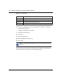
Point-to-Point Protocol
The PPP family of protocols is divided into three categories:
•
•
•
Control protocols control operation and maintenance of the PPP link.
Network protocols describe the encapsulation methods needed to move
multiprotocol network traffic over the PPP interface.
Network control protocols are used to configure, manage, and control the
operation of the network protocols. The Passport 8683POS Module uses the
Link Control Protocol (LCP) and the Link Quality Report to monitor the link.
PPP goes through the following basic initialization phases when bringing up links:
•
•
Link establishment
Network layer protocol
Establishing the PPP link
The Link Control Protocol (LCP) of the PPP helps establish a link. LCP generates
three types of packets:
•
•
•
Link configuration packets, including configure-request, configure-ACK,
configure-NAK, and configure-reject packets
Link termination packets, including terminate-request and terminate-ACK
packets
Link maintenance packets, including code-reject, protocol-reject,
echo-request, and echo-reply packets
When two devices initialize a PPP dialog, each sends a configure-request packet
to the other. Each configure-request packet contains a list of LCP options and
corresponding values that the sending device uses to define its end of the link.
Using the Passport 8683POS Module
32
Chapter 2 Using the Passport 8683POS Module
For example, a configure-request packet may specify the link’s maximum
transmission unit (MTU) size. The configure-request packet contains the
user-configured values, which the sending device and the receiving device may
need to negotiate.
When the receiving device gets a configure-request packet from the sending
device, the receiving device responds with one of the following three types of
packets:
•
•
•
configure-ACK (that is, configure acknowledgment),
configure-reject, or
configure-NAK (that is, configure negative acknowledgment).
When the receiving device accepts the proposed LCP options, it responds with a
configure-ACK packet. When the devices on each side of the link send and
receive configure-ACK packets, the LCP advances to an open state, which means
that the PPP interface can advance to the next phase. The devices converge.
When the configure-request packet from the sending device contains options that
the receiving device is not willing to negotiate, the receiving device sends back a
configure-reject packet specifying the nonnegotiable options. From that point on,
configure-request packets from the sending device should eliminate the
unacceptable options. When the sending device eliminates the offending options,
the devices converge.
When the receiving device disagrees with some or all of the values of the
proposed options in the configure-request packet, it responds with a
configure-NAK packet. The configure-NAK packet notes the values that the
receiving device disagrees with, and it includes the corresponding values that the
receiving device would like to see in subsequent configure-request packets.
LCP negotiations between sending and receiving devices continue until either:
•
•
•
209564-A
Both devices converge (reach an agreement regarding the configure-request).
The receiving device transmits a specified number of configure-NAK packets
before sending a configure-reject packet.
The convergence timer expires.
Chapter 2 Using the Passport 8683POS Module
33
Negotiating network layer protocols
PPP uses various network control protocols to determine the values of parameters
during network layer negotiations, which is the final phase of PPP initialization.
Similar to the LCP, each network control protocol allows the devices to negotiate
various network options over the data link by transmitting configure-request,
configure-ACK, configure-NAK, and configure-reject packets.
Networks options include which network addresses to use and which media types
to bridge. Once both devices agree upon networks options, the network control
protocol reaches the open state. The devices then begin transmitting user data
packets for upper-layer protocols over the link.
Spanning tree group feature
The BPDU (Bridge Protocol Data Unit) format specified in RFC 1638 is enabled
by default on the Passport 8683POS Module. If support for multiple spanning tree
groups is required, the BPDU default format must first be disabled. For
information on changing the STG format, see “config pos ppp” on page 95.
Using the Passport 8683POS Module
34
Chapter 2 Using the Passport 8683POS Module
209564-A
35
Chapter 3
Installing the Passport 8683POS Module
This chapter describes the procedure for installing the Passport 8683POS Module.
It covers the following topics:
•
•
•
•
•
•
“Safety and environmental precautions,” next
“Installing the Passport 8683POS Module” on page 37
“Verifying installation” on page 40
“Initialization” on page 40
“MDA insertion and configuration” on page 42
“Replacing a module” on page 43
For more information about the Passport 8600 chassis, refer to the following
documents:
•
•
•
Getting Started with Passport 8000 Series Management Software
Using the Passport 8600 Modules
Installing the Passport 8600 Modules
Safety and environmental precautions
Before you begin performing any installation or replacement procedure on the
Passport switch, please note the following safe handling guidelines:
•
To prevent damage caused by electrostatic discharge (ESD), handle the switch
chassis and modules only when you, the chassis, and the chassis modules are
properly grounded. Nortel Networks recommends the use of a grounding
wrist strap.
Using the Passport 8683POS Module
36
Chapter 3 Installing the Passport 8683POS Module
•
When handling modules, do not touch components on the modules; always
handle modules by their edges. Store unused modules in their protective
packaging.
Warning: Fiber optic equipment can emit laser or infrared light that can
injure your eyes. Never look into an optical fiber or connector port.
Always assume that fiber optic cables are connected to a light source.
Vorsicht: Glasfaserkomponenten können Laserlicht bzw. Infrarotlicht
abstrahlen, wodurch Ihre Augen geschädigt werden können. Schauen Sie
niemals in einen Glasfaser-LWL oder ein Anschlußteil. Gehen Sie stets
davon aus, daß das Glasfaserkabel an eine Lichtquelle angeschlossen ist.
Avertissement: L’équipement à fibre optique peut émettre des rayons
laser ou infrarouges qui risquent d’entraîner des lésions oculaires. Ne
jamais regarder dans le port d’un connecteur ou d’un câble à fibre
optique. Toujours supposer que les câbles à fibre optique sont raccordés
à une source lumineuse.
Advertencia: Los equipos de fibra óptica pueden emitir radiaciones de
láser o infrarrojas que pueden dañar los ojos. No mire nunca en el
interior de una fibra óptica ni de un puerto de conexión. Suponga
siempre que los cables de fibra óptica están conectados a una fuente
luminosa.
Avvertenza: Le apparecchiature a fibre ottiche emettono raggi laser o
infrarossi che possono risultare dannosi per gli occhi. Non guardare mai
direttamente le fibre ottiche o le porte di collegamento. Tenere in
considerazione il fatto che i cavi a fibre ottiche sono collegati a una
sorgente luminosa.
8769EB
209564-A
Chapter 3 Installing the Passport 8683POS Module
37
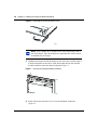
Installing the Passport 8683POS Module
To install the Passport 8683POS Module:
1
Remove the filler panel from the module slot in the Passport 8000 series
chassis (Figure 5).
Figure 5 Removing the filler panel
9058FB
Note: If you are removing a module from the slot in which you want to
place the new Passport 8683POS Module, be sure to:
• Remove all port interface cables
• Release the insertor/extractor levers of the I/O module, and swing
them out.
2
Make sure the inserter/extractor levers are extended away from the Passport
8683POS Module front panel (Figure 6).
Using the Passport 8683POS Module
38
Chapter 3 Installing the Passport 8683POS Module
Figure 6 Extending the inserter/extractor levers
9059FA
Note: Always handle an I/O module by the sides and carefully slide it
out of the chassis. Place the module on a grounded work surface and in
an antistatic bag for storage.
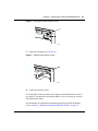
3
Handling the Passport 8683POS Module by the sides only, carefully align it
with the card guides in the chassis. Slide the module into the slot until the
module connectors touch the chassis backplane (Figure 7).
Figure 7 Inserting the Passport 8683POS Module
Diag Port
Link
Console
MDA1
MDA 2
MDA 3
8683POS
Online
10041FA
4
209564-A
Rotate the inserter/extractor levers to seat the backplane connectors
(Figure 8).
Chapter 3 Installing the Passport 8683POS Module
39
Figure 8 Closing the inserter/extractor levers
MDA 1
MDA 2
8672 ATM
Online
10037FA
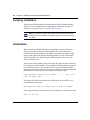
5
Tighten the retaining screws (Figure 9).
Figure 9 Tightening the retainer screws
MDA 1
MDA 2
8672 ATM
Online
10038FA
6
Connect the interface cables.
You must install at least one MDA on the Passport 8683POS Module in order to
pass traffic. For instructions on installing MDAs, refer to Installing the Passport
8683POS Module MDAs.
For information on configuring and managing the Passport 8683POS Module,
refer to Chapter 4, “Managing the Passport 8683POS Module,” on page 45.
Using the Passport 8683POS Module
40
Chapter 3 Installing the Passport 8683POS Module
Verifying installation
The Passport 8683POS Module front panel has an Online LED that indicates
whether or not the module has power applied and is initialized correctly. For
information on online LEDs, see “Online LED” on page 27.
Note: You cannot configure the Passport 8683POS Module until the
online LED on the module is steadily lit and you have inserted at least
one MDA.
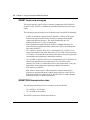
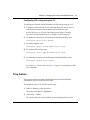
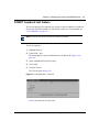
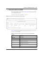
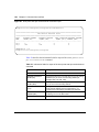
Initialization
When the Passport 8683POS Module is installed into a Passport 8600 series
chassis, ensure that the Passport 8690SF module in the same chassis has a
PCMCIA card inserted and that the PCMCIA card contains the p80p3100.dld
image, which supports the Passport 8683POS Module. For more information
about the PCMCIA slot and the Passport 8690SF module, refer to Using the
Passport 8600 Modules.
The Passport 8690SF module retrieves the image file p80t3100.dld to download
to the Passport 8683POS Module. First, the Passport 8690SF module searches the
host flash memory for the file, then the PCMCIA card. The Passport 8690SF
module downloads the image file to the Passport 8683POS Module and identifies
which MDAs are installed. The screen displays following message:
Downloading POS image to slot <number> .........Done (file
name and image size.)
If the image file is not found in either the flash memory or the PCMCIA, the
screen displays this message:
POS image file name not found either in FLASH or PCMCIA.
If the image download is unsuccessful, the screen displays the following message:
Card is off line.
209564-A
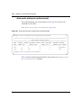
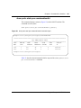
Chapter 3 Installing the Passport 8683POS Module
41
The Passport 8683POS Module requests a redownload from the Passport 8690SF
module, and the screen displays this message:
Redownload requested by POS card in slot <number>.
The Passport 8683POS Module attempts a redownload three times. If the
download is still unsuccessful, the Passport 8683POS Module goes offline and the
screen displays this message:
Redownload of POS card in slot <number> failed maximum 3
times; POS card is offline.
When the Passport 8683POS Module boots, the redownload count is reset to 0.
After the image loads onto the Passport 8683POS Module, it performs a series of
self-diagnostic tests. If the module fails the diagnostics, the screen displays the
following message:
Port <number> for POS card in slot <number> failed
diagnostics.
If you see this message, contact a service representative. For information on
contacting service representatives, refer to “How to get help” on page 21.
When the image successfully loads onto the Passport 8683POS Module, the
screen displays the following message:
POS card in slot <number> is online.
The Passport 8690SF Module can download the image to multiple Passport
8683POS Modules in the same Passport 8600 series chassis simultaneously.
Note: If you accidentally delete the image file, reset the card and
redownload the file. For information on how to reset the card, see
“Resetting the module” on page 50.
Using the Passport 8683POS Module
42
Chapter 3 Installing the Passport 8683POS Module
If you have one MDA installed, you can proceed to configure the Passport
8683POS Module.
Note: You must save your configuration (using either the CLI or Device
Manager) to preserve the configuration changes you made to the
Passport 8683POS Module across reboots.
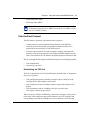
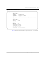
MDA insertion and configuration
Once you insert an MDA, you must complete some basic configuration tasks for
the Passport 8683POS Module to begin switching operations as soon as it
completes initialization. For information on installing MDAs, refer to Installing
the Passport 8683POS Module MDAs.
To verify that the Passport 8683POS Module is ready to receive and transmit
traffic, check the LEDs on the module and the MDA. Once you enable the ports
using the CLI or Device Manager, the online LED on the module lights steady
green, and the module is ready. See “Online LED” on page 27 and “MDA LEDs”
on page 28.
For information on enabling ports, refer to “Enabling or disabling a port” on
page 59.
You configure and manage the Passport 8600 series switch operation for your
network using the command line interface (CLI) or SNMP-based network
management software, such as Device Manager. For information on configuring
and managing the Passport 8683POS Module, refer to Chapter 4, “Managing the
Passport 8683POS Module,” on page 45.
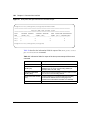
Factory default settings for the Passport 8683POS Module are shown in Table 9
on page 54.
209564-A
Chapter 3 Installing the Passport 8683POS Module
43
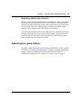
Replacing a module
You can hot-swap Passport 8683POS Modules as long as the module you are
removing has the same MDAs installed as the module you are inserting. In this
case, the system saves the configuration. If you hot-swap the module with a
module that has different MDAs installed, you must reconfigure the module.
If you are hot-swapping modules, read the following section for information about
how the routing switch recognizes replacement modules and how to avoid
potential problems.
Warning: The Passport 8683POS Module itself is hot-swappable; the
MDAs necessary to pass traffic on the module are not hot-swappable.
Starting the system after a module replacement
After you replace a module on your chassis, you can expect the following results:
•
•
•
In a running system, when you replace an input/output (I/O) module with a
module of the same type, the system restores the configuration of all the ports.
When you replace a module with one of a different type, the system discards
the configuration of the old ports, and the new ports are added to either the
default VLAN or a null VLAN, depending on the operating mode of the
switch.
When you save the configuration in nonvolatile random access memory
(NVRAM), turn off the switch, replace a module with a different module
type, and turn the system on again, the system discards the configuration of
the old ports, and adds new ports to either the default VLAN or an unassigned
VLAN, depending on the operating mode of the switch.
Starting the system with an empty slot
When you save the configuration in NVRAM, shut down the system, remove a
module, turn on the chassis with that slot empty, and then populate the slot with a
module of the same type as the one previously there, the system is not able to
restore the original configuration.
Using the Passport 8683POS Module
44
Chapter 3 Installing the Passport 8683POS Module
209564-A
45
Chapter 4
Managing the Passport 8683POS Module
Two management tools enable you to manage the Passport 8683POS Module:
Device Manager and command line interface (CLI). You can also use the
embedded web-based management feature to monitor the Passport 8683POS
Module. See Chapter 7, “Web management,” on page 131 for information on
using the web-based management feature.
This chapter contains information on these topics:
•
•
•
•
•
•
“Port numbering,” next
“Device Manager” on page 46
“Command line interface” on page 53
“Configuration procedures” on page 54
“Trap feature” on page 71
“SONET loopback test feature” on page 75
Port numbering
You must insert an MDA into the Passport 8683POS Module in order to have
connectivity. The module contains three slots for MDAs, and you can mix and
match from among the following MDAs, which are available (SMF and MMF):
•
•
1-port OC-12c/STM-4
2-port OC-3c/STM-1
The management system identifies an interface by its slot number in the Passport
8600 series chassis and its port number, using the syntax slot number/port number
(s/p). Because the Passport 8683POS Module can have up to six ports with three
2-port MDAs inserted, port numbers 1 and 2 are reserved for the MDA in the left
Using the Passport 8683POS Module
46
Chapter 4 Managing the Passport 8683POS Module
slot regardless of the actual physical number of ports. Port numbers 3 and 4 apply
to the MDA in the middle slot regardless of the actual physical number of ports;
and port numbers 5 and 6 apply to the MDA in the right slot regardless of the
physical number of ports.
For example, a Passport 8683POS Module in the second slot of the Passport 8600
series chassis with an OC-12c/STM-4 MDA in the left slot, an OC-3c/STM-1
MDA in the middle, and an OC-12c/STM-4 MDA in the right slot has the
following port numbers for management and configuration:
•
•
•
•
2/1: OC-12c/STM-4
2/3: OC-3c/STM-1, left port
2/4: OC-3c/STM-1, right port
2/5: OC-12c/STM-4
As another example of port numbering, an Passport 8683POS Module in the
second slot of the chassis with an OC-3c/STM-1 MDA in the left slot, the middle
slot blank, and an OC-12c/STM-4 installed in the right slot has the following port
numbers:
•
•
•
2/1: OC-3c/STM-1, left port
2/2: OC-3c/STM-1, right port
2/5: OC-12c/STM-4
A Passport 8683POS Module with three OC-3c/STM-1 MDAs installed has ports
numbered consecutively 1 through 6, from left to right.
Device Manager
Passport Device Manager is an SNMP-based graphical user interface tool
designed to manage single devices. In order to use Device Manager, you must
have network connectivity to a management station running Device Manager on
one of the supported platforms.
209564-A
Chapter 4 Managing the Passport 8683POS Module
47
For detailed information on all aspects of installing and running Device Manager,
refer to:
•
•
•
Getting Started with the Passport 8000 Series Management Software
Reference for Passport 8000 Series Management Software Routing
Operations, and
Reference for Passport 8000 Series Management Software Switching
Operations.
This section describes the Device Manager features that are specific to the
Passport 8683POS Module.
Device Manager access and passwords
Table 3 shows the security access levels for the Passport 8683POS Module.
Table 3 Passport 8683POS Module access levels
Level of Access
Passport 8683POS Module feature
Level 1 (read/write)
SONET parameters
Level 2 (read/write)
All PPP bridging and Spanning Tree parameters
Level 3 (read/write)
All IP and IPX routing parameters
Refer to the Reference for Passport 8000 Series Management Software Switching
Operations for information on using Device Manager to set the CLI login and
access passwords.
Installing Device Manager
To install Device Manager:
1
Download the Device Manager software from the CD.
2
Double-click the icon and follow the instructions on the screen.
Using the Passport 8683POS Module
48
Chapter 4 Managing the Passport 8683POS Module
When you launch Device Manager, a graphical image of the Passport 8600
chassis with the Passport 8683POS Module installed is displayed (Figure 10).
Figure 10 Passport 8600 series chassis with Passport 8683POS Module
209564-A
Chapter 4 Managing the Passport 8683POS Module
49
The ports on the graphical image are color-coded to provide at-a-glance port
status. Table 4 shows the status assigned to each color code.
Table 4 Passport Device Manager port color codes
Field
Description
Green
Port is operating.
Red
Port has been manually disabled.
Orange
Port has no link.
Light blue
Port is in standby mode.
Dark blue
Port is being tested.
Gray
Port is unmanageable.
Additionally, many Device Manager windows and dialog boxes contain buttons.
Table 5 describes the function of these buttons.
Table 5 Passport Device Manager buttons
Field
Description
Apply
Applies the changes you entered to fields in a window or dialog box.
Refresh
Refreshes the information in the window. Each time you click Refresh,
new information is polled from the switch and is displayed.
Close
Closes the window or dialog box and disregards any changes you
made to fields.
Help
Does not function with the Passport 8683POS Module.
Insert
Inserts or creates new information.
Resize Columns Resizes columns on the screen.
Note: You must always click Apply at the bottom of the tab to
implement any changes you make.
Using the Passport 8683POS Module
50
Chapter 4 Managing the Passport 8683POS Module
Resetting the module
To reset the module:
1
Highlight the card.
2
Choose Edit > Card.
The Card dialog box opens with the Card tab displayed (Figure 11).
Figure 11 Card tab
209564-A
Chapter 4 Managing the Passport 8683POS Module
51
Table 6 describes the fields in the Card tab.
Table 6 Card tab fields
Field
Description
FrontType
Card type.
FrontDescription
Packet Over Sonet.
FrontAdminStatus
The administrative status of the card.
FrontOperStatus
The operational status of the card.
FrontSerialNum
Serial number of card.
FrontHwVersion
Hardware version.
FrontPartNumer
Part number.
FrontDateCode
Date code.
FrontDeviations
Deviations.
BackType
Card back type.
BackDescription
Description.
BackSerialNum
Serial Number.
BackHwVersion
Hardware version.
BackPartNumer
Part number.
BackDateCode
Date code.
BackDeviations
Deviations.
3
Click the POS tab.
The POS tab opens (Figure 12).
Figure 12 POS tab
Using the Passport 8683POS Module
52
Chapter 4 Managing the Passport 8683POS Module
Table 7 describes the fields in the POS tab.
Table 7 POS tab fields
Field
Description
Action: reset
Resets the card.
ImageFileName
Name of the image file which downloads at initialization.
4
Click reset.
5
Click Apply.
To reset the card using the CLI, see “Configuration commands” on page 92.
Viewing MDA information
To view information on the MDA you are using:
1
Highlight the MDA.
2
Select Edit > Mda.
The MDA dialog box opens (Figure 13).
Figure 13 MDA dialog box
209564-A
Chapter 4 Managing the Passport 8683POS Module
53
Table 8 describes the fields in the MDA dialog box.
Table 8 MDA dialog box fields
Field
Description
Type
Media type:
• OC-3c SMF MDA
• OC-3c MMF MDA
• OC-12c SMF MDA
• OC-12c MMF MDA
Description
MDA description:
• OC-3c SMF MDA—Dual port OC-3c SMF
• OC-3c MMF MDA—Dual port OC-3c MMF
• OC-12c SMF MDA — Single Port OC-12c SMF
• OC-12c MMF MDA —Single Port OC-12c MMF
Command line interface
Using the command line interface (CLI), you can perform most module
management tasks. For detailed information on all aspects of the CLI, refer to:
•
•
•
Getting Started with the Passport 8000 Series Management Software
Reference for Passport 8000 Series Command Line Interface Switching
Operations, and
Reference for the Passport 8000 Series Command Line Interface Routing
Operations.
The CLI identifies an interface by its slot number in the Passport 8600 chassis and
its port number, using the syntax slot number/port number (s/p). Refer to “Port
numbering” on page 45 for information on the slot and port numbering for the
Passport 8683POS Module.
Using the Passport 8683POS Module
54
Chapter 4 Managing the Passport 8683POS Module
Configuration procedures
You can configure the Passport 8683POS Module in two basic modes:
•
•
Bridging: Bridging mode is enabled by default. Bridging is configured for
connections between two Passport 8683POS Modules and between Passport
8683POS Modules and other devices that support PPP bridging.
Routing: You select routing mode for connections between your Passport
8683POS Module and other POS-capable routers for IP and IPX routing.
Use Device Manager and/or CLI to perform these configuration and related tasks
on the Passport 8683POS Module. For information on advanced configurations,
refer to Getting Started with Passport 8000 Series Management Software.
This section describes the following:
•
•
•
“Default configurations,” next
“Basic procedures” on page 55
“Configuring bridging” on page 62
Default configurations
The Passport 8683POS Module has the following default configurations.
Table 9 describes the default settings.
Table 9 Passport 8683POS Module default settings
209564-A
Parameter
Default
Bridge Admin State (BCP)
Open
IP Admin State (IPCP)
Close
IPX Admin State (IPXCP)
Close
Clock source
Line
FCS size
32
Debug
Disabled
Framing
SONET
Priority
Low
Chapter 4 Managing the Passport 8683POS Module
55
Table 9 Passport 8683POS Module default settings (continued)
Parameter
Default
Lock
False
Lqr interval
100
Lqr status
Enabled
Lqr threshold
95
Magic number
True
Oversize frame
Disabled
Perform tagging
Disabled
Scramble
Enabled
Signal-Label (C2)
0x16
Section trace (J0)
1 (0x01)
STP RFC 1638
Enabled
Tagged frame discard
Disabled
Unknown MAC discard
Disabled
Untagged frame discard
Disabled
Device Manager interval
10 seconds
Basic procedures
To change the default settings on the Passport 8683POS Module or to perform any
configuration tasks in Device Manager, select the port you want to configure and
open the Interface tab.
To open the Interface tab:
Do one of the following:
•
•
Right-click on the port. A shortcut menu opens. Choose Edit.
Double-click on the port.
The Port dialog box opens with the Interface tab displayed (Figure 14).
This tab displays information about the port and allows you to configure
various elements.
Using the Passport 8683POS Module
56
Chapter 4 Managing the Passport 8683POS Module
Figure 14 Port dialog box — Interface tab
209564-A
Chapter 4 Managing the Passport 8683POS Module
57
Table 10 describes the Interface tab items.
Table 10 Interface tab items
Item
Description
Index
Unique value assigned to each interface. The value ranges between
16 and 255.
Name
Displays the name of this port. To assign or change a name to the port,
highlight the field and enter alphanumeric characters.
Descr
Type of interface, either:
• OC-3c MMF or SMF
• OC-12c MMF or SMF
Type
Media type of this interface. This will be ppp for a port on the Passport
8683POS Module.
Mru
Size (in octets) of the largest packet that can be sent or received on
the interface. For IPCP and IPXCP, the maximum is 1936. When BCP
is enabled, however, the maximum is 1934. Check which NCP is
enabled before configuring the Mru on a connecting device.
Note: The Bridge Control Protocol (BCP) is enabled on the Passport
8683POS Module by default.
PhysAddress
MAC address assigned to a particular interface.
VendorDescr
Vendor description.
AdminStatus
Sets the port to one of the following states:
• up
• down
• testing
When a managed system initializes, all interfaces start with
AdminStatus in the down state. As a result of either management or
configuration action, the AdminStatus is changed to the up state (or
remains in the down state). The testing state indicates that no
operational packets can be passed.
OperStatus
Operational state of the interface, one of the following:
• up
• down
• testing
The testing state indicates that no operational packets can be passed.
If AdminStatus is down, then OperStatus should be down.
If AdminStatus is changed to up, then OperStatus should change to
up if the interface is ready to transmit and receive network traffic.
It should remain in the down state if and only if there is a fault that
prevents it from going to the up state.
Using the Passport 8683POS Module
58
Chapter 4 Managing the Passport 8683POS Module
Table 10 Interface tab items (continued)
Item
Description
LastChange
Value of sysUpTime at the time the interface entered its current
operational state. If the current state was entered prior to the last
reinitialization of the local network management subsystem, the value
is zero.
LinkTrap
Sets whether or not link Up/link Down traps should be generated for
this interface.
• enabled—sends traps for link up or down
• disabled—does not send traps for link up or down
OperDuplex
Current operational duplex of the port (half or full). This will always be
full duplex on a POS port.
OperSpeed
Current operating speed of the port. It can be either 155 or 622 Mb/s
depending on the type of interface installed.
MltId
Multi-Link Trunk to which the port is assigned (if any).
Locked
Displays whether or not the port is locked. When locked, the port
configuration cannot be changed. To lock or unlock a port, select Edit
> Security > Port Lock.
Action
Sets one of the following port-related actions:
• none
• flushMacFdb—flush MAC forwarding table for port
• flushArp—flush ARP table for port
• flushIp—flush IP route table for port
• flushAll—flush all tables for port
• triggerRipUpdate—manually update the RIP table
Result
Displays results from the last system action.
From the Interface tab, select other POS-specific tabs to configure the port or
change current or default configurations.
209564-A
Chapter 4 Managing the Passport 8683POS Module
59
Enabling or disabling a port
Note: When you change configurations in Device Manager, and hit the
Apply button, the system will disable and re-enable the port
automatically.
You can enable or disable a port by two methods. To enable or disable a port
through the Device Manager menu bar:
1
Highlight the port.
2
From the Device Manager menu bar, choose Edit > Port.
The Port dialog box opens with the Interface tab displayed (Figure 14 on
page 56).
3
In AdminStatus area, click up to enable the port, or click down to disable the
port.
4
Click Apply.
To enable or disable a port using a shortcut menu:
1
Right-click on the port.
A shortcut menu opens.
2
Choose Enable or Disable.
SONET parameters
To change the default parameters, you configure the values for the Synchronous
Optical Network (SONET) media in the POS SONET tab. These values must be
configured before you configure POS PPP, VLAN, or any other parameters.
See Table 9 on page 54 for the default SONET parameters.
To change the configuration of the SONET parameters:
1
Highlight the port.
Using the Passport 8683POS Module
60
Chapter 4 Managing the Passport 8683POS Module
2
Choose Edit > Port.
The Port dialog box opens with the Interface tab displayed (Figure 14 on
page 56).
3
Disable the port as described in “Enabling or disabling a port” on page 59.
4
In the Interface tab, click the POS SONET tab.
The POS SONET tab opens (Figure 15).
Figure 15 Port dialog box — POS SONET tab
209564-A
Chapter 4 Managing the Passport 8683POS Module
61
Table 11 describes the items in the POS SONET tab.
Table 11 POS SONET tab items
Item
Description
SonetFraming
Sets the framing for the port to:
• SONET—Synchronous Optical Network format;
standard format used in North America (default)
•
SDH—Synchronous Digital Hierarchy clock
format; standard format used in Europe.
SonetOperStatusFraming
Operational value of SONET framing.
SonetSectionTrace
Sets the integer that the section trace flag (j0) is set
to, that is an integer between 1 and 255.
SonetOperStatusSectionTrace
Operational value of SonetSectionTrace.
SonetOperStatusPathSignalLabel
Operational value of Path Signal Label.
SonetClockSource
Sets the Clock Source to either line or internal.
SonetOperStatusClockSource
Operational value of ClockSource.
SonetScramble
Parameter that enables or disables the scrambling
option.
SonetOperStatusScramble
Operational value of SonetScramble.
SonetMedium
MediumType
Identifies whether a SONET or a SDH signal is
used across this interface.
MediumTimeElapsed
Number of seconds, including partial seconds, that
have elapsed since the beginning of the current
measurement period. If, for some reason, such as
an adjustment in the system’s time-of-day clock, the
current interval exceeds the maximum value, the
agent will return the maximum value.
MediumValidIntervals
Number of previous 15-minute intervals for which
data was collected.
MediumLineCoding
Line coding for this interface. The Non-Return to
Zero (NRZ) line coding is used for optical SONET/
SDH signals.
MediumLineType
Line type for this interface. The line types are single
mode fiber or multimode fiber interfaces.
MediumCircuitIdentifier
Transmission vendor’s circuit identifier, for the
purpose of facilitating troubleshooting. Note that the
circuit identifier, if available, is also represented by
ifPhysAddress.
Using the Passport 8683POS Module
62
Chapter 4 Managing the Passport 8683POS Module
5
Select the SonetClockSource, either line or internal.
If two Passport POS Modules are operating directly (that is, connected back to
back, without any intervening Sonet equipment), one port must provide the
clock source. Set the clock source of one port to internal, and the opposite port
must be set to line.
6
Select other SONET parameters.
7
Click Apply.
8
Re-enable the port as described in “Enabling or disabling a port” on page 59.
Configuring bridging
The Passport 8683POS Module is configured for bridging by default. The
configuration is set for bridging between two Passport 8683POS Modules with
one default VLAN. The Bridge Control Protocol (BCP) is enabled on the Passport
8683POS Module by default.
Note: When the POS link is enabled after a parameter change or a
chassis reset, some superfluous traffic may initially be sent out of POS
ports before any LCP packets go out. This is normal.
You can also configure bridging for the Passport 8683POS Module for connection
to other POS-capable devices.
209564-A
Chapter 4 Managing the Passport 8683POS Module
63
Configuring routing
A POS port configured for IPCP and/or IPXCP encapsulation must be the sole
member of the VLAN. You cannot add any other port to a VLAN which already
has a POS port with IPCP and/or IPXCP encapsulation enabled. You cannot add a
POS port which is configured for IPCP and/or IPXCP encapsulation to a VLAN
which already has other ports as members.
Note: When the Passport 8600 switch is interoperating with a Juniper
router, the POS port must have the Juniper IP address configured in the
remote IP field. This is necessary because the Juniper routers do not
provide their local IP address during PPP negotiation. The Passport 8600
switch requires the Juniper address for IPCP operations. See “config pos
ip” on page 94 for information on configuring the remote IP address.
Note also that 30-bit subnet masks may be required for certain JUNOS
releases.
Configuring IP routing using Device Manager
To configure the Passport 8683POS Module for IP routing using Device Manager:
1
Highlight the port.
2
Choose Edit > port.
The Port dialog box opens with the Interface tab displayed (Figure 14 on
page 56).
3
Click the POS PPP tab.
The POS PPP tab opens (Figure 16).
Using the Passport 8683POS Module
64
Chapter 4 Managing the Passport 8683POS Module
Figure 16 Port dialog box — POS PPP tab
209564-A
Chapter 4 Managing the Passport 8683POS Module
65
Table 12 describes the POS PPP tab items
Table 12 POS PPP tab items
Area
Item
Description
Link
LinkConfigMagicNumber
If set to enable, selects a random number (“magic number”)
used in loopback detection. Enable detects loopback; disable
does not detect loopback.
OperStatusLinkMagicNumber Operational value of LinkConfigMagicNumber.
Bridge
IP
IPX
LinkConfigFcsSize
Configures the size (in bits) of cyclic redundancy check field
used in PPP frame.
LinkStatusTransmitFcsSize
Operational value of LinkConfigFcsSize.
BridgeAdminConfigStatus
This parameter enables or disables bridged traffic with in
PPP.
BridgeOperStatus
Operational value of BridgeAdminConfigStatus.
LineConfigPppStp
Enables BPDUs to be received or transmitted with BPDU
specific encapsulation. When disabled encapsulated within
Ethernet frames.
OperStatusLinePppStp
Enables or disables PPP.
IpConfigAdminStatus
Enables or disables the IP traffic (link) with in PPP.
IpOperStatus
Operational value of IP link.
LineConfigRemoteIPAddr
Configured value of remote end IP address.
LineStatusRemoteIPAddr
Negotiated value of the remote end IP address.
IpxcpAdminStatus
Enables or disables the IPX traffic (link) with in PPP.
IpxOperStatus
Operational value of IPX link.
RoutingProtocol
Sets the IPX Routing Protocol to none or RIP.
LineStatusIpxRoutingProtocol Negotiated value of RoutingProtocol.
LQR
LqrConfigStatus
Sets the link quality reporting to enabled or disabled.
OperStatusLqrStatus
Negotiated value of LqrConfigStatus.
LqrConfigPeriod
Sets the link quality-reporting interval in 100th of a second.
LineStatusLocalPeriod
Negotiated value of LqrConfigPeriod.
LineConfigLqrThreshold
Sets input quality threshold in percent.
OperStatusLqrThreshold
Operational value of LineConfigLqrThreshold.
4
In the BridgeConfigAdminStatus section, click close to disable bridging.
Using the Passport 8683POS Module
66
Chapter 4 Managing the Passport 8683POS Module
5
To enable IP routing, in the IpConfigAdminStatus field, click open.
6
To configure an IP address for the port:
a
Highlight the port.
b
Choose Edit > Port.
The Port dialog box opens with the Interface tab displayed (Figure 14 on
page 56).
c
Click the IP Address tab.
The IP address tab opens (Figure 17).
Figure 17 Port dialog box — IP Address tab
Table 13 describes the fields in the IP Address tab.
Table 13 IP Address tab fields
Field
Description
IpAddress
IP address to which the entry’s addressing information pertains.
NetMask
The subnet mask associated with the IP address of the entry.
BcastAddrFormat
The IP broadcast address format used on this interface.
ReasmMaxSize
The size of the largest IP datagram which this entity can
re-assemble from incoming IP fragmented datagrams received on
this interface.
VlanId
Unique VLAN identifier.
BrouterPort
indicates whether this entry corresponds to a brouter port (as
oppose to a routable VLAN). This value cannot be changed after
the row is created.
d
Click Insert.
The Port, Insert IP Address dialog box opens (Figure 18).
209564-A
Chapter 4 Managing the Passport 8683POS Module
67
Figure 18 Port, Insert IP Address dialog box
Table 14 describes the Port, Insert IP Address dialog box items.
Table 14 Insert IP Address dialog box items
Item
Description
Ip Address
IP address to which the entry’s addressing information pertains.
Net Mask
The subnet mask associated with the IP address of the entry.
VlanId
Unique VLAN identifier.
e
Type the IP address and click Insert.
The IP address displays in the table in the IP Address tab (Figure 17).
7
Click Apply.
8
To enable the port on both Passport 8683POS Modules, click the Interface tab
and, in the AdminStatus field, click up.
9
Click Apply.
Configuring IP routing using the CLI
To configure the Passport 8683POS Modules for IP routing using the CLI:
1
To disable the selected port on both Passport 8683POS Modules, enter:
config pos <ports> state disable
2
To disable bridging, enter:
config pos <ports> bridge-admin-status close
Using the Passport 8683POS Module
68
Chapter 4 Managing the Passport 8683POS Module
3
To configure IP routing, enter:
config pos <ports>> ppp ip-admin-status open
4
To configure an IP address on the selected port on both Passport 8683POS
Modules, enter:
config pos <ports> ip create <ipaddr/mask> <vid>
5
To enable the selected port on both Passport 8683POS Modules, enter:
config pos <ports> state enable
See Chapter 6, “Command line interface,” on page 91 for descriptions of the CLI
commands.
Configuring IPX routing using Device Manager
When you use IPXCP encapsulation, you must select Ethernet II as the MAC
encapsulation for the protocol-based VLANs. IPXCP supports only the Ethernet
II format.
To configure the Passport 8683POS Modules for IPX routing using Device
Manager:
1
Configure an Ethernet II protocol-based VLAN.
1
Highlight the port.
2
Choose Edit > port.
The Port dialog box opens with the Interface tab displayed (Figure 14 on
page 56).
Refer to Reference for Passport 8000 Series Management Software Routing
Operations for information on how to configure VLANs using Device
Manager.
3
Disable the port as described in “Enabling or disabling a port” on page 59.
4
To configure the VLAN as an IPX protocol-based VLAN and assign the port
to the VLAN:
a
209564-A
From the Device Manager menu bar, choose VLAN > VLAN.
Chapter 4 Managing the Passport 8683POS Module
69
The VLAN dialog box opens with the Basic tab displayed (Figure 19).
Figure 19 VLAN dialog box — Basic tab
Table 15 describes the fields in the Basic tab.
Table 15 Basic tab fields
Field
Description
Id
Unique VLAN identifier.
Name
An administratively-assigned name for this VLAN.
ColorIdentifier
An administratively-assigned color code for this VLAN. The value
of this object is used by the VLAN Manager GUI tool to select a
color when it draws this VLAN on the screen.
Type
Type of VLAN, distinguished according to the policy used to
define its port membership.
StgId
Spanning Tree Group (STG) used by the VLAN to determine the
state of its ports. If the VLAN is not associated with any STG, this
value should be set to zero.
PortMembers
Set of ports that are members (static or dynamic) of this VLAN.
ActiveMembers
Set of ports that are currently active in this VLAN. Active ports
include all static ports and any dynamic ports where the VLAN
policy was met.
StaticMembers
Set of ports that are static members of this VLAN. A static
member of a VLAN is always active and is never aged out.
NotAllowtoJoin
Set of ports that are not allowed to become members of this
VLAN.
ProtocolId
Protocol identifier of this VLAN. This value is meaningful only if
rcVlanType is equal to byProtocolId(3). For other VLAN types it
should have the value none(0).
Using the Passport 8683POS Module
70
Chapter 4 Managing the Passport 8683POS Module
Table 15 Basic tab fields (continued)
Field
Description
SubnetAddr
IP subnet address of this VLAN. This value is meaningful only if
rcVlanType is equal to byIpSubnet(2). For other VLAN types it
should have the value 0.0.0.0.
SubnetMask
IP subnet mask of this VLAN. This value is meaningful only if
rcVlanType is equal to byIpSubnet(2). For other VLAN types it
should have the value 0.0.0.0.
5
6
7
8
209564-A
b
To assign the POS ports to the VLAN as static members, enter the ports in
the StaticMembers column.
c
To assign all other ports to the VLAN as active members, enter the ports
in the ActiveMembers column.
d
Enter the POS ports in the NotAllowToJoin column.
e
Click Apply.
To disable bridging:
a
Click the POS PPP tab.
b
In the Bridge area, BridgeConfigAdminStatus field, click Close.
To enable IPX routing on each selected port:
a
Click the POS PPP tab.
b
In the IPX area, IpxcpAdminStatus field, click Open.
To enable the port on both Passport 8683POS Modules:
a
Click the Interface tab.
b
In the AdminStatus field, click Up.
Click Apply.
Chapter 4 Managing the Passport 8683POS Module
71
Configuring IPX routing using the CLI
To configure the Passport 8683POS Modules for IPX routing using the CLI:
1
Configure a protocol-based VLAN. and assign the port to the VLAN as a
static member and ensure that no other ports are allowed to join.
Refer to Reference for Passport 8000 Management Software Routing
Operations for information on how to configure VLANs using CLI.
2
To disable the selected port on both Passport 8683POS Modules, enter:
config pos <ports> state disable
3
To disable bridging, enter:
config pos <ports> bridge-admin-status close.
4
To configure IPX routing, enter:
config pos <ports> ppp ipx-admin-status open.
5
To enable the selected port on both Passport 8683POS Modules, enter:
config pos <ports> state enable
See Chapter 6, “Command line interface,” on page 91 for descriptions of the
CLI commands.
Trap feature
The Passport 8600 chassis with a functioning Passport 8683POS Module
automatically receives SONET-specific traps.
To configure the device for SONET-specific traps:
1
In Device Manager, select the chassis.
The frame of the chassis is highlighted.
2
Choose Edit > Chassis.
The Chassis dialog box opens with the System tab displayed (Figure 20).
Using the Passport 8683POS Module
72
Chapter 4 Managing the Passport 8683POS Module
Figure 20 Chassis dialog box — System tab
3
Click the Trap Receivers tab.
The Trap Receivers tab opens (Figure 21).
Figure 21 Chassis dialog box — Trap Receivers tab
209564-A
Chapter 4 Managing the Passport 8683POS Module
73
Table 16 describes the fields in the Trap Receivers tab.
Table 16 Trap Receivers tab fields
Field
Description
IpAddress
IP address to which the entry’s addressing information pertains.
Community
Community string used for trap messages to this trap receiver.
Version
Version
4
Click Insert.
The Chassis, Insert Trap Receivers dialog box opens (Figure 22).
Figure 22 Chassis, Insert Trap Receiver dialog box
Table 17 describes the fields in the Insert Trap Receiver dialog box.
Table 17 Insert Trap Receiver dialog box fields
Field
Description
IpAddress
IP address to which the entry’s addressing information pertains.
Community
Community string used for trap messages to this trap receiver
Version
Version
5
Enter the IP address of the device you are monitoring and click Insert.
The dialog box closes and the Trap Receivers tab is redisplayed.
6
Click Apply.
Using the Passport 8683POS Module
74
Chapter 4 Managing the Passport 8683POS Module
Viewing the Trap Log
To view the Trap Log that contains SONET-specific traps:
Click the bell icon on the toolbar.
The Trap dialog box opens (Figure 23).
Figure 23 Trap Log dialog box
Table 18 describes the fields in the Trap Log dialog box.
Table 18 Trap Log dialog box fields
209564-A
Field
Description
Node
IP address of the device sending SONET trap.
Time
Timestamp in the trap.
Type
Type of SONET trap: Section/Line/Path alarm.
Description
Description of the alarm: LOS, LOF, and so forth.
Chapter 4 Managing the Passport 8683POS Module
75
SONET loopback test feature
This section describes the loopback test features in Device Manager available for
the Passport 8683POS Module. For information on the CLI test commands, see
“Test commands” on page 127.
Note: All ports must be in test mode to conduct any testing.
To test for loopback:
1
Highlight the port.
2
Choose Edit > port.
The Port dialog box opens with the Interface tab displayed (Figure 14 on
page 56).
3
In the AdminStatus field, click testing.
4
Click Apply.
5
Click the Test tab.
The Test tab opens (Figure 24).
Figure 24 Port dialog box — Test tab
Table 19 describes the Test tab items.
Using the Passport 8683POS Module
76
Chapter 4 Managing the Passport 8683POS Module
Table 19 Test tab items
Item
Description
Result
Result of the test.
Code
Code used for test.
PassCount
Number of events which passed the test.
FailCount
Number of events which failed the test.
6
Click Ext. Loopback to test the external loopback or click Int. Loopback to
test the internal loopback.
A dialog box displays the test results.
7
Click Stop to cease testing.
8
Click Close.
9
Click the Interface tab.
10 In the AdminStatus field, click up.
11 Click Apply.
Note: To run the external loopback test, you need a loopback cable on
that port.
The test statistics are available only when the test has finished, unlike Ethernet
ports where the test statistics can be viewed during testing.
209564-A
Chapter 4 Managing the Passport 8683POS Module
77
Alarms
Using Device Manager or the CLI, you can enable RMON globally or on a
port-by-port basis. Implementing RMON lets you set alarms relating to specific
events or variables.
Refer to Reference for the Passport 8000 Series Management Software Switching
Operations for more information on alarms.
Table 20 lists the alarms that are specific to the Passport 8683POS Module. The
alarms are listed in order of priority.
Table 20 Passport 8683POS Module alarms
Name
Description
Section alarms
LOS
Loss of signal - not enough Rx power or fiber disconnected.
LOF
Loss of frame - unable to frame the signal correctly, possibly due
to improper timing setup.
Line Alarms
L-AIS
Alarm Indication Signal - sent out when a port is disabled or
indicates another line failure.
L-RDI
Remote Defect Indication - the result of a L-AIS or LOS/LOF at
the remote end.
Path Alarms
P-AIS
Path Alarm Indication Signal - indicates a propagation upstream
of a downstream L-AIS alarm or another path failure.
P-LOP
Path Loss of Pointer - the pointer to the Sonet SPE is not correct;
sometimes due to dirty fiber, or timing slips.
P-RDI
Path Remote Indicator - the result of a P-AIS alarm at the remote
end.
P-SLM
Path Signal Label Mismatch - path labels do not match, in
particular the C2 label is mismatched. (The C2 label is used to
indicate scrambling according to RFC 2615.)
P-UNEQ
Path is unequipped - the path is may not be provisioned to handle
traffic cross-connects.
Using the Passport 8683POS Module
78
Chapter 4 Managing the Passport 8683POS Module
209564-A
79
Chapter 5
Graphing statistics in Device Manager
This chapter contains information on the following topics:
•
•
“Overview,” next
“Displaying statistics” on page 80
For more information about using Passport Device Manager, refer to Reference
for Passport 8000 Series Management Software Switching Operations, Release
3.1 and Reference for Passport 8000 Series Management Software Routing
Operations, Release 3.1
Overview
Device Manager allows you to graph and display certain statistics for the Passport
8683POS Module.
Refer to Reference for the Passport 8000 Series Management Software Switching
Operations, Release 3.1 for complete details on graphing statistics.
The values for the POS, PPP Link, and PPP LQR tabs are displayed for absolute,
cumulative, average, minimum, maximum, and last values.
Table 21 describes these values.
Using the Passport 8683POS Module
80
Chapter 5 Graphing statistics in Device Manager
Table 21 Types of statistics
Field
Description
AbsoluteValue
The total count since the last reset of counters. A system reboot resets
all counters.
Cumulative
The total count since the statistics tab was first opened. The elapsed
time for the cumulative counter is displayed at the bottom of the
statistics window.
Average
The cumulative count divided by the cumulative elapsed time.
Minimum
The minimum average for the counter for a given polling interval over
the cumulative elapsed time.
Maximum
The maximum average for the counter for a given polling interval over
the cumulative elapsed time.
LastValue
The average for the counter over the last polling period.
The values for the POS, PPP Link, and PPP LQR tabs are updated based on the
poll interval. For information on how to set the poll interval, refer to Reference for
the Passport 8000 Series Management Software Switching Operations, Release
3.1.
Displaying statistics
The Passport 8683POS Module provides the following statistics tabs:
•
•
•
•
•
•
•
•
209564-A
“Viewing POS statistics,” next
“Viewing PPP Link statistics” on page 83
“Viewing PPP LQR” on page 84
“Viewing Section statistics” on page 86
“Viewing Line statistics” on page 87
“Viewing FE Line statistics” on page 88
“Viewing Path statistics” on page 90
“Viewing FE Path statistics” on page 91
Chapter 5 Graphing statistics in Device Manager
81
Note: The windows displaying statistics are read-only.
Viewing POS statistics
To display statistics POS statistics:
1
On the device view, right-click the port.
2
Choose Graph POS.
The graphSonetPort dialog box opens with the POS tab displayed (Figure 25).
Figure 25 graphSonetPort dialog box — POS tab
Table 22 describes the fields in the POS tab.
Table 22 POS tab fields
Field
Description
InErrors
Number of inbound packets that contained errors preventing
them from being deliverable to a higher-layer protocol.
InUnknownProtos
Number of packets received via the interface which were
discarded because of an unknown or unsupported protocol.
OutErrors
Number of outbound packets that contained errors preventing
them from being deliverable to a higher-layer protocol.
Using the Passport 8683POS Module
82
Chapter 5 Graphing statistics in Device Manager
Table 22 POS tab fields (continued)
Field
Description
HCInOctets
The total number of octets received on the interface, including
framing characters.
HCInUcastPkts
Number of packets delivered by this sub-layer to a higher
(sub-)layer, which were not addressed to a multicast or
broadcast address at this sub-layer.
HCInMulticastPkts
Number of packets delivered by this sub-layer to a higher
(sub-)layer, which were addressed to a multicast address at
this sub-layer.
HCInBroadcastPkts
Number of packets, delivered by this sub-layer to a higher
(sub-)layer, which were addressed to a broadcast address at
this sub-layer.
HCInDiscards
Number of inbound packets which were chosen to be
discarded even though no errors had been detected to
prevent their being deliverable to a higher-layer protocol.
HCOutOctets
The total number of octets transmitted out of the interface,
including framing characters.
HCOutUcastPkts
Number of packets that higher-level protocols requested be
transmitted, and which were not addressed to a multicast or
broadcast address at this sub-layer, including those that were
discarded or not sent.
HCOutMulticastPkts
Number of packets that higher-level protocols requested be
transmitted, and which were addressed to a multicast address
at this sub-layer, including those that were discarded or not
sent.
HCOutBroadcastPkts
Number of packets that higher-level protocols requested be
transmitted, and which were addressed to a broadcast
address at this sub-layer, including those that were discarded
or not sent.
HCOutDiscards
Number of outbound packets which were chosen to be
discarded.
Viewing PPP Link statistics
To display PPP Link statistics:
209564-A
1
On the device view, right-click the port.
2
Choose Graph Port.
Chapter 5 Graphing statistics in Device Manager
83
The graphSonetPort dialog box opens with the POS statistics tab displayed
(Figure 25).
3
Click the PPP Link tab.
The PPP Link tab opens (Figure 26).
Figure 26 graphSonetPort dialog box — PPP Link tab
Table 23 describes the fields in the PPP Link tab.
Table 23 PPP Link tab fields
Field
Description
BadAddresses
Number of packets received with an Incorrect Address Field.
This counter is a Component of the ifInErrors variable that is
associated with the interface that represents this PPP Link.
BadControls
Number of packets received on this link with an incorrect Control
Field. This counter is a component of the ifInErrors variable that
is associated with the interface that represents this PPP Link.
BadFCSs
LocalMRU
PacketTooLongs
Number of received packets that have been discarded because
their length exceeded the MRU. This counter is a component of
the ifInErrors variable that is associated with the interface that
represents this PPP Link. NOTE: packets which are longer than
the MRU but which are successfully received and processed are
NOT included in this count.
Using the Passport 8683POS Module
84
Chapter 5 Graphing statistics in Device Manager
Viewing PPP LQR
To display PPP LQR statistics:
1
On the device view, right-click the port.
2
Choose Graph Port.
The graphSonetPort dialog box opens with the POS statistics tab displayed
(Figure 25).
3
Click the PPP LQR tab.
The PPP LQR tab opens (Figure 27).
Figure 27 graphSonetPort dialog box — PPP LQR tab
Table 24 describes the fields in the PPP LQR tab.
209564-A
Chapter 5 Graphing statistics in Device Manager
85
Table 24 PPP LQR tab fields
Field
Description
Quality
Quality number.
InGoodOctets
Number of good octets received on the interface.
LocalPeriod
Time interval in 100th of a second between link quality reporting
from local end.
RemotePeriod
Time interval in 100th of a second between link quality reporting
from remote end.
OutLQRs
Value of the OutLQRs counter on the local node for the link.
InLQRs
Value of the InLQRs counter on the local node for the link.
Viewing Section statistics
To display Section statistics:
1
On the device view, right-click the port.
2
Choose Graph Port.
The graphSonetPort dialog box opens with the POS statistics tab displayed
(Figure 25 on page 81).
3
Click the Section tab.
The Section tab opens (Figure 28).
Figure 28 graphSonetPort dialog box — Section tab
Using the Passport 8683POS Module
86
Chapter 5 Graphing statistics in Device Manager
Table 25 describes the fields in the Section tab.
Table 25 Section tab fields
Field
Description
ESs
Errored Second (ES) is a second with one or more Coding Violations
or one or more incoming defects, for example, SEF, LOS, AIS, LOP.
SESs
Severely Errored Second (SES) is a second with x or more CVs, or a
second during which at least one or more incoming defects.
SEFSs
Severely Errored Framing Second (SEFS) is a second containing one
or more SEF events.
CVs
Coding Violations (CV) are Bit Interleaved Parity (BIP) errors that are
detected in the incoming signal. CV counters are incremented for
each BIP error detected.
Viewing Line statistics
To display Line statistics:
1
On the device view, right-click the port.
2
Choose Graph Port.
The graphSonetPort dialog box opens with the POS statistics tab displayed
(Figure 25 on page 81).
3
Click the Line tab.
The Line tab opens (Figure 29).
Figure 29 graphSonetPort dialog box — Line tab
Table 26 describes the fields in the Line tab.
209564-A
Chapter 5 Graphing statistics in Device Manager
87
Table 26 Line tab fields
Field
Description
ESs
Errored Second (ES) is a second with one or more Coding Violations
or one or more incoming defects, for example, SEF, LOS, AIS, or LOP.
SESs
Severely Errored Second (SES) is a second with x or more CVs, or a
second during which at least one or more incoming defects.
CVs
Coding Violations (CV) are Bit Interleaved Parity (BIP) errors that are
detected in the incoming signal. CV counters are incremented for
each BIP error detected.
UASs
Number of seconds that the interface is unavailable.
Viewing FE Line statistics
To display FE Line statistics:
1
On the device view, right-click the port.
2
Choose Graph Port.
The graphSonetPort dialog box opens with the POS statistics tab displayed
(Figure 25 on page 81).
3
Click the FE Line tab.
The FE Line tab opens (Figure 30).
Figure 30 graphSonetPort dialog box — FE Line tab
Using the Passport 8683POS Module
88
Chapter 5 Graphing statistics in Device Manager
Table 27 describes the fields in the FE Line tab.
Table 27 FE Line tab fields
Field
Description
ESs
Errored Second (ES) is a second with one or more Coding Violations
or one or more incoming defects, for example, SEF, LOS, AIS, or LOP.
SESs
Severely Errored Second (SES) is a second with x or more CVs, or a
second during which at least one or more incoming defects.
CVs
Coding Violations (CV) are Bit Interleaved Parity (BIP) errors that are
detected in the incoming signal. CV counters are incremented for
each BIP error detected.
UASs
Number of seconds that the interface is unavailable.
Viewing Path statistics
To display Path statistics:
1
On the device view, right-click the port.
2
Choose Graph Port.
The graphSonetPort dialog box opens with the POS statistics tab displayed
(Figure 25 on page 81).
3
Click the Path tab.
The Path tab opens (Figure 31).
Figure 31 graphSonetPort dialog box — Path tab
209564-A
Chapter 5 Graphing statistics in Device Manager
89
Table 28 describes the fields in the Path tab.
Table 28 Path tab fields
Field
Description
ESs
Errored Second (ES) is a second with one or more Coding Violations
or one or more incoming defects, for example, SEF, LOS, AIS, or LOP.
SESs
Severely Errored Second (SES) is a second with x or more CVs, or a
second during which at least one or more incoming defects.
CVs
Coding Violations (CV) are Bit Interleaved Parity (BIP) errors that are
detected in the incoming signal. CV counters are incremented for
each BIP error detected.
UASs
Number of seconds that the interface is unavailable.
Viewing FE Path statistics
To display Path statistics:
1
On the device view, right-click the port.
2
Choose Graph Port.
The graphSonetPort dialog box opens with the POS statistics tab displayed
(Figure 25 on page 81).
3
Click the FE Path tab.
The FE Path tab opens (Figure 32).
Figure 32 graphSonetPort dialog box — FE Path tab
Using the Passport 8683POS Module
90
Chapter 5 Graphing statistics in Device Manager
Table 29 describes the fields in the FE Path tab.
Table 29 FE Path tab fields
209564-A
Field
Description
ESs
Errored Second (ES) is a second with one or more Coding Violations
or one or more incoming defects, for example, SEF, LOS, AIS, or LOP.
SESs
Severely Errored Second (SES) is a second with x or more CVs, or a
second during which at least one or more incoming defects.
CVs
Coding Violations (CV) are Bit Interleaved Parity (BIP) errors that are
detected in the incoming signal. CV counters are incremented for
each BIP error detected.
UASs
Number of seconds that the interface is unavailable.
91
Chapter 6
Command line interface
This chapter contains information about the CLI commands relevant to the
Passport 8683POS Module. For more information about the CLI for Passport 3.1,
refer to:
•
•
•
Getting Started with Passport 8000 Series Management Software, Release 3.1
Reference for the Passport 8000 Series Command Line Interface Switching
Operations, Release 3.1
Reference for the Passport 8000 Series Command Line Interface Routing
Operations, Release 3.1
This chapter contains the following topics:
•
•
•
•
“Configuration commands,” next
“Show commands” on page 99
“Monitor commands” on page 126
“Test commands” on page 127
Using the Passport 8683POS Module
92
Chapter 6 Command line interface
Configuration commands
This section describes the configuration commands available with the Passport
8683POS Module. There are two types of configuration commands:
•
•
Module commands
Port commands
Note: If you replace one card with another type of card, Nortel
Networks recommends that you go to the root level of the CLI directory
before you use any CLI commands.
config poscard commands
The config poscard command allows you to:
•
•
•
Reset the module
Enable trace messages
Display the image filename for the Passport 8683POS Module
The syntax is:
config poscard <posslot number>
where <posslot number> is the slot number of the module in the Passport 8600
chassis.
Table 30 describes the parameters and variables for the config poscard
command.
209564-A
Chapter 6 Command line interface
93
Table 30 config poscard command parameters and variables
Parameters and variables
Description
card-reset
Resets the card.
debug <enable | disable>
Enables or disables trace messages on the module to
be displayed on the console of the switch.
info
Displays the image filename and debug mode for the
module.
pos-console <enable | disable> Prints the trace message POS card. This is a priv
command. When the pos-console is enabled (on the
host), POS prints trace messages on the POS console.
You can also use this command to query information on
the POS card or port. To use this command, you must
be in priv mode. The syntax to enter priv mode is:
config/poscard/<port number>/priv
Port commands
The port commands allow you to perform general configuration on the Passport
8683POS Module. The syntax for the port config commands is:
•
•
•
•
•
•
config
config
config
config
config
config
pos
pos
pos
pos
pos
pos
<ports>
<ports>
<ports>
<ports>
<ports>
<ports>
ip
ppp
sonet
stg
info
The port commands, variables and parameters and sub-commands are described
in the following sections.
config pos command
Table 31 describes the parameters and variables for the config pos <ports>
command.
Using the Passport 8683POS Module
94
Chapter 6 Command line interface
Table 31 config pos command parameters and variables
Parameters and variables
Description
default-vlan-id <vid>
Directs the switch to send the untagged frames to a default VLAN if
received on a tagged port. <vid> is the VLAN ID of the default VLAN
to which the discarded frames are sent.
info
Shows the last saved port settings and the next-level CLI commands.
Note that this does not show the current settings, but the last saved
settings.
linktrap <enable | disable>
Enables or disables the link up or down trap for a port.
lock <true | false>
Locks a port for exclusive use if the port lock feature is globally
enabled with the command config sys set portlock on
name <name>
Assign or set a name.
perform-tagging <enable |
disable>
Enables or disables the IEEE 802.1Q tagging on the port.
state <enable | disable | test>
Sets the state to enable, disable, or test.
tagged-frames-discard <enable |
disable>
Sets a port with tagging disabled to discard tagging frames.
untagged-frames-discard <enable
| disable>
Sets a port with tagging enabled to discard untagged frames.
config pos ip
Use the config pos ip command to configure IP parameters on the Passport
8683POS Module.
Note: When the Passport 8600 switch is interoperating with a Juniper
router, the POS port must have the Juniper IP address configured. This is
necessary because the Juniper routers do not provide their local IP
address during PPP negotiation. The Passport 8600 switch requires the
Juniper address for IPCP operations.
Table 32 describes the parameters and variables for the config pos ip
command.
209564-A
Chapter 6 Command line interface
95
Table 32 config pos ip command parameters and variables
Parameters and variables
Description
create <ipaddr/mask> <vid>
[mac_offset <value>]
Creates an IP address and assigns it to a VLAN, with the VLAN ID.
delete <ipaddr>
Deletes the IP address.
info
Shows the last saved port settings and the next-level CLI commands.
Note that this does not show the current settings, but the last saved
settings.
config pos ppp
Use the config pos ppp command to configure Point-to-Point Protocol (PPP)
parameters on the Passport 8683POS Module.
Table 33 describes the parameters and variables for the config pos ppp
command.
Using the Passport 8683POS Module
96
Chapter 6 Command line interface
Table 33 config pos ppp command parameters and variables
Parameters and variables
Description
bridge-admin-status <open |
close>
Enables or disables the bridge control protocol.
fcs-size<32 | 16>
Sets the length of the redundancy check (fcs) to either 32 or 16.
info
Shows the last saved port settings and the next-level CLI commands.
Note that this does not show the current settings, but the last saved
settings.
ip-admin-status <open | close>
Enables or disables the IP control protocol.
ipx-admin-status <open | close>
Enables or disables the IPX control protocol.
ipx-route-protocol <none | rip>
Sets the protocol for IPX routing.
lqr-period <interval>
Sets the link quality reporting interval. Enter time in ms.
lqr-status <enable | disable>
Enables or disables link quality reporting.
lqr-threshold <threshold>
Sets the link quality reporting threshold. Enter %.
magic-number <true | false>
Sets a random number (“magic number”) used in loopback detection.
True detects loopback; false does not detect loopback.
ppp-stpmode <enable | disable>
Encapsulates spanning tree BPDU packets as PPP. When enabled
the BPDUs are encapsulated as in RFC 1638. When disabled, the
BPDUs travel as bridged data (assuming bridge-admin-status is
enabled).
remote-ip<ipaddr>
Sets the remote iP address.
config pos sonet command
Use the config pos sonet command to configure SONET parameters on the
Passport 8683POS Module.
Table 34 describes the parameters and variables for the config pos sonet
command.
209564-A
Chapter 6 Command line interface
97
Table 34 config pos sonet command parameters and variables
Parameters and variables
Description
clock-source <internal | line>
Sets the clock source to:
• <internal>, which means clocking is derived from on-board
clock.
• <line>, which means clocking is derived from line.
Note that if you have two connected modules, you must set both to
internal or one to line and one to internal; do not set both to line.
framing <sonet | sdh>
Sets the framing to:
• <sonet>, which means the Synchronous Optical Network
format, the standard format used in North America.
• <sdh>, which means the Synchronous Digital Hierarchy clock
format, the standard format used in Europe.
info
Shows the last saved port settings and the next-level CLI commands.
Note that this does not show the current settings, but the last saved
settings.
signal label
Operational value of Path Signal Label (C2). The signal label value is
reset when the scramble value is changed.
scramble <enable | disable>
Enables or disables scrambling.
section-trace <sectiontrace>
Sets the integer that the section trace flag (j0) is set to (1...255).
z0-increment
Enables or disables z0 when the framing mode is set to SONET. This
is a priv command - to use this command, you must be in privilege
mode.The syntax to enter priv mode is: config/pos/<port
number>/sonet priv
config pos stg command
Use the config pos stg command to configure STG parameters on the
Passport 8683POS Module.
Using the Passport 8683POS Module
98
Chapter 6 Command line interface
Table 35 describes the parameters and variables for the config pos stg
command.
Table 35 config pos stg command parameters and variables
Parameters and variables
Description
faststart <enable | disable>
Enables or disables the fast start flag.
info
Shows the last saved port settings and the next-level CLI commands.
Note that this does not show the current settings, but the last saved
settings.
pathcost <intval>
Sets the contribution of this port to the path cost.
priority <intval>
Sets the priority of this port.
stg <enable | disable>
Enables or disables spanning tree protocol.
config pos info command
The config pos info command shows the current state of the port.
Figure 33 shows a sample of the output from the config pos info command.
Figure 33 config pos info command sample output
Passport-8610:5/config# pos 10/5 info
Port 10/5 :
lock : false
name :
unknown-mac-discard : disable
default-vlan-id : 1
perform-tagging : disable
tagged-frames-discard : disable
untagged-frames-discard : disable
state : up
linktrap : enable
port-type : OC3-MMF
Passport-8610:5/config#
209564-A
Chapter 6 Command line interface
99
Show commands
This section describes the show commands available with the Passport 8683POS
Module. These commands allow you to view information about the module:
show ports info pos [<ports>]
show ports stats pos activealarms [<ports>]
show ports stats pos felinecurrent [<ports>]
show ports stats pos felineinterval <intervalid> [<ports>]
show ports stats pos fepathcurrent [<ports>]
show ports stats pos fepathinterval <intervalid> [<ports>]
show ports stats pos linecurrent [<ports>]
show ports stats pos lineinterval <intervalid> [<ports>]
show ports stats pos linkstatus [<ports>]
show ports stats pos lqrstatus [<ports>]
show ports stats pos pathcurrent [<ports>]
show ports stats pos pathinterval <intervalid> [<ports>>]
show ports stats pos pppiftbl [<ports>]
show ports stats pos sectioncurrent [<ports>]
show ports stats pos sectioninterval <intervalid> [<ports>]
show ports stats pos sonetmediumtbl [<ports>]
show tech
Refer to the Reference for the Passport 8000 Series Command Line Interface
Routing Operations, Release 3.1 and Reference for the Passport 8000 Series
Command Line Interface Switching Operations, Release 3.1 for a complete list of
CLI commands.
Using the Passport 8683POS Module
100
Chapter 6 Command line interface
show ports info pos
The show ports info pos command displays information (Figure 34)
about the configuration for a specified port on the Passport 8683POS Module.
The command uses the syntax: show ports info pos [<ports>] and options:
all, ppp, sonet in the following syntax:
show ports info pos all
show ports info pos ppp
show ports info pos sonet
show ports info pos all
Figure 34 shows sample output for the show ports info pos all
command, which includes information for the PPP and SONET parameters.
209564-A
Chapter 6 Command line interface
101
Figure 34 show ports info pos all command output
Passport-8610:5/show/ports/info/pos# all
========================================================================
SONET Config Info
========================================================================
PORT FRAMING
CLOCK
SECTION
SIGNAL
NUM
MODE
SOURCE
TRACE
LABEL SCRAMBLE
-----------------------------------------------------------------------10/1
sonet
line 1
0x16 enable
10/3
sonet
internal 1
0x16
enable
=========================================================================
SONET Local Operational Info
=========================================================================
PORT FRAMING
CLOCK
SECTION
SIGNAL
NUM
MODE
SOURCE
TRACE
LABEL SCRAMBLE
------------------------------------------------------------------------10/1
sonet
line
1
0x16
enable
10/3
sonet
internal 1
0x16
enable
=======================================================================
PPP Config Info
=======================================================================
PORT ADMIN
BRIDGE
IP
IPX
MAGIC PPP
NUM
STATUS
ADMIN
ADMIN
ADMIN
NUMBERSTPMODE LQSTATUS
-----------------------------------------------------------------------10/1
up
open
close
close
false enable enable
10/3
up
open
close
close
false enable enable
PORT
FCS IPX ROUTE LQR-QUAL
LQR-QUAL
NUM
SPEED
MRU
SIZE PROTOCOL
THRESHOLD PERIOD REMOTE IP
------------------------------------------------------------------10/1
OC3-MMF 1936 32
rip
95
100
0.0.0.0 -M
10/3
OC3-MMF 1936 32
rip
95
100
0.0.0.0 -M
PORT IPX NET
NUM ADDR
------------------------------------------------------------------10/1 0000000
10/3 0000000
================================================================================
PPP Local Operational Info
================================================================================
PORT STATUS
LCP
BRIDGE
IP
IPX
MAGIC
NUM
OPERATE
STATUS
STATUS
STATUS
STATUS
NUMBER
STPMODE
------------------------------------------------------------------------10/1
up
up
down
up
down
false enable
10/3
up
up
down
up
down
false enable
Using the Passport 8683POS Module
102
Chapter 6 Command line interface
Figure 35 show ports info pos all command output (continued)
PORT PPP
FCS IPX ROUTE LQR-QUAL
LQR-QUAL
NUM
LQSTATUS
MRU
SIZE PROTOCOL
THRESHOLD PERIOD
REMOTE IP
----------------------------------------------------------------------------10/1 enable
1936
32
none
95
100
10.32.6.14
10/3
enable
1936
32
none
95
100
10.32.6.10
PORT IPX NET
NUM
ADDR
---------------------------------------------------------------------------10/1
00000000
10/3
00000000
=====================================================================
Other Info
=====================================================================
PORT POS S/W PLD
FRAMER CARD
NUM
VERSION VERSION VERSION VERSION
--------------------------------------------------------------------10/1
51
7
2
POS 7
Passport-8610:5/show/ports/info/pos# all
Table 36 describes the fields for output of the show ports info pos all
command
209564-A
Chapter 6 Command line interface
103
.
Table 36 Information fields for output of the show ports info pos all
command
Field
Description
PORT NUM
Port number.
FRAMING MODE
Indicates whether the framing mode is either:
• sonet
• sdh
CLOCK SOURCE
Indicates whether the clock source is either:
• line
• internal
SECTION TRACE
Indicates the integer that the section trace flag (j0) is set to.
SIGNAL LABEL
Operational value of Path Signal Label (C2). The signal
label value is reset when the scramble value is changed.
SCRAMBLE
Enables or disables the scrambling option.
ADMIN STATUS
Sets the port to one of the following states:
• up
• down
• testing
BRIDGE ADMIN
This parameter indicates bridged traffic within PPP.
IP ADMIN
This parameter indicates the IP traffic (link) within PPP.
IPX ADMIN
This parameter indicates the IPX traffic (link) within PPP.
MAGIC NUMBER
If set to enable, selects a random number (“magic
number”) used in loopback detection. enable detects
loopback; disable does not detect loopback.
STPMODE
Spanning Tree Protocol mode - This parameter enables
BPDUs to be received or transmitted with BPDU specific
encapsulation. When disabled, encapsulated within
Ethernet frames.
PPP LQSTATUS
Sets the link quality reporting interval.
SPEED
Displays the current operating speed of the port. It can be
either 155 or 622 Mb/s depending on the type of interface
installed.
Using the Passport 8683POS Module
104
Chapter 6 Command line interface
Table 36 Information fields for output of the show ports info pos all
command (continued)
Field
Description
MRU
Size (in octets) of the largest packet that can be sent or
received on the interface. For IPCP and IPXCP, the
maximum is 1936. When BCP is enabled, however, the
maximum is 1934. Check which NCP is enabled before
configuring the Mru.
Note: The Bridge Control Protocol (BCP) is enabled on the
Passport 8683POS Module by default.
FCS SIZE
Sets the length of the redundancy check (fcs) to either 32
or 16.
IPX ROUTE PROTOCOL
Sets the protocol for IPX routing.
LQR-QUAL THRESHOLD
Indicates the link quality reporting threshold.
LQR-QUAL PERIOD
Indicates the link quality reporting interval.
REMOTE IP
Indicates the remote iP address.
IPX NET ADDR
Indicates the IPX net address.
STATUS OPERATE
Operational status.
LCP STATUS
Link Control Protocol status.
BRIDGE STATUS
Bridging status.
IP STATUS
Routing (IP) status.
IPX STATUS
Routing (IPX) status
PPP LQSTATUS
Point-to-Point status
show ports stats pos activealarms
This command displays active alarms on the Passport 8683POS Module port. The
command uses the syntax:
show ports stats pos activealarms [<ports>]
Figure 36 shows output for the show ports stats pos activealarms
command.
209564-A
Chapter 6 Command line interface
105
Figure 36 show ports stats pos activealarms command output
Passport-8610:5/show/ports# stats pos activealarms
=======================================================
Active Alarms
=======================================================
PORT
NUM
ACTIVE ALARM
--------------------------------------------------------10/5
No Defect
10/6
LOS
Passport-8610:5/show/ports/stats/pos#
Table 37 describes the information fields for output for the show ports
stats pos activealarms command.
Table 37 Information fields for output of the show ports stats pos activealarms
command
Field
Description
PORT NUM
Port number.
ACTIVE ALARM
Displays which port has active alarms.
show ports stats pos felinecurrent
This command displays current statistics on the far end line, which is at the
receiving end. The command uses the syntax:
show ports stats pos felinecurrent [<ports>]
Figure 37 shows sample output for the show ports stats pos
felinecurrent command.
Using the Passport 8683POS Module
106
Chapter 6 Command line interface
Figure 37 show ports stats pos felinecurrent command output
Passport-8610:5/show/ports/stats/pos# felinecurrent
======================================================================
POS Far End Line Current Stats
======================================================================
PORT
ERRORED SECONDS
SEVERELY ERRORED
CODE VIOLATION UNAVAILABLE
NUM
COUNT (ES)
COUNT (SES)
COUNT (CV-L) SECONDS(UAS)
---------------------------------------------------------------------10/5
0
0
0
0
10/6
0
0
0
0
Passport-8610:5/show/ports/stats/pos#
Table 38 describes the information fields for output of the show ports stats
pos felinecurrent command.
Table 38 Information fields for output of the show ports stats pos felinecurrent
command
209564-A
Field
Description
PORT NUM
Port number.
ERRORED SECONDS
COUNT (ES)
Errored Second (ES) is a second with one or more Coding
Violations (CV) or one or more incoming defects (for
example, SEF, LOS, AIS, LOP).
SEVERELY ERRORED
COUNT (SES)
Severely Errored Second (SES) is a second with x or more
CVs, or one or more incoming defects.
CODE VIOLATION COUNT
(CV-L)
Coding Violations (CV) are Bit Interleaved Parity (BIP)
errors that are detected in the incoming signal. CV
counters are incremented for each BIP error detected.
UNAVAILABLE SECONDS
Number of seconds that the interface is unavailable.
Chapter 6 Command line interface
107
show ports stats pos felineinterval
This command displays statistics (Figure 38) on the far end line over a 15-minute
interval. You specify which interval, or span of intervals, to display for the
command. The command uses the syntax:
show ports stats pos felineinterval <intervalid> [<ports> ]
Figure 38 show ports stats pos felineinterval command output
Passport-8610:5/show/ports/stats/pos# felineinterval 4
======================================================================
POS Far End Line Interval Stats
======================================================================
PORT
ERRORED SECONDS
SEVERELY ERRORED
CODE VIOLATION UNAVAILABLE
NUM
COUNT (ES)
COUNT (SES)
COUNT (CV-L) SECONDS(UAS)
---------------------------------------------------------------------10/5
0
0
0
0
10/6
0
0
0
0
INTERVAL ID = 4
Passport-8610:5/show/ports/stats/pos#
Table 39 describes the information fields for output of the show ports stats
pos felineinterval command
Using the Passport 8683POS Module
108
Chapter 6 Command line interface
Table 39 Information fields for output of the show ports stats pos felineinterval
command
Field
Description
PORT NUM
Port number.
ERRORED SECONDS
COUNT (ES)
Errored Second (ES) is a second with one or more Coding
Violations (CV) or one or more incoming defects (for
example, SEF, LOS, AIS, LOP).
SEVERELY ERRORED
COUNT (SES)
Severely Errored Second (SES) is a second with x or more
CVs, or one or more incoming defects.
CODE VIOLATION COUNT
(CV-L)
Coding Violations (CV) are Bit Interleaved Parity (BIP)
errors that are detected in the incoming signal. CV
counters are incremented for each BIP error detected.
UNAVAILABLE SECONDS
(UAS)
Number of seconds that the interface is unavailable.
INTERVAL ID
Specified interval.
show ports stats pos fepathcurrent
This command displays current statistics (Figure 39) for the far end path, which is
at the receiving end. The command uses the syntax:
show ports stats pos fepathcurrent [<ports>]
Figure 39 show ports stats pos fepathcurrent command output
Passport-8610:5/show/ports/stats/pos# fepathcurrent
=========================================================================
POS Far End Path Current Stats
=========================================================================
PORT
ERRORED SECONDS
SEVERELY ERRORED
CODE VIOLATION
UNAVAILABLE
NUM
COUNT (ES)
COUNT (SES)
COUNT (CV-P)
SECONDS(UAS)
------------------------------------------------------------------------10/1
0
0
0
0
10/3
0
0
0
527
Passport-8610:5/show/ports/stats/pos#
209564-A
Chapter 6 Command line interface
109
Table 40 describes the information fields for output of the show ports stats
pos fepathcurrent command.
Table 40 Information fields for output of the show ports stats pos fepathcurrent
command
Field
Description
PORT NUM
Port number.
ERRORED SECONDS
COUNT (ES)
Errored Second (ES) is a second with one or more Coding
Violations (CV) or one or more incoming defects (for
example, SEF, LOS, AIS, LOP).
SEVERELY ERRORED
COUNT (SES)
Severely Errored Second (SES) is a second with x or more
CVs, or one or more incoming defects.
CODE VIOLATION COUNT
(CV-P)
Coding Violations (CV) are Bit Interleaved Parity (BIP)
errors that are detected in the incoming signal. CV
counters are incremented for each BIP error detected.
UNAVAILABLE SECONDS
(UAS)
Number of seconds that the interface is unavailable.
show ports stats pos fepathinterval
This command displays statistics (Figure 40) on the far end path over a 15-minute
interval. You specify the interval or span of intervals to display. The command
uses the syntax:
show ports stats pos fepathinterval <intervalid> [<ports>]
Using the Passport 8683POS Module
110
Chapter 6 Command line interface
Figure 40 show ports stats pos fepathinterval command output
Passport-8610:5/show/ports/stats/pos# fepathinterval 1
=========================================================================
POS Far End Path Interval Stats
=========================================================================
PORT
ERRORED SECONDS
SEVERELY ERRORED
CODE VIOLATION
UNAVAILABLE
NUM
COUNT (ES)
COUNT (SES)
COUNT (CV-P)
SECONDS(UAS)
-----------------------------------------------------------------------10/1
0
0
0
0
10/3
0
0
0
900
INTERVAL ID = 1
Passport-8610:5/show/ports/stats/pos#
Table 41 describes the information fields for output of the show ports stats
pos fepathinterval command.
Table 41 Information fields for output of the show ports stats pos fepathinterval
command
209564-A
Field
Description
PORT NUM
Port number.
ERRORED SECONDS
COUNT (ES)
Errored Second (ES) is a second with one or more Coding
Violations (CV) or one or more incoming defects (for
example, SEF, LOS, AIS, LOP).
SEVERELY ERRORED
COUNT (SES)
Severely Errored Second (SES) is a second with x or more
CVs, or one or more incoming defects.
CODE VIOLATION COUNT
(CV-P)
Coding Violations (CV) are Bit Interleaved Parity (BIP)
errors that are detected in the incoming signal. CV
counters are incremented for each BIP error detected.
UNAVAILABLE SECONDS
(UAS)
Number of seconds that the interface is unavailable.
INTERVAL ID
Specified interval.
Chapter 6 Command line interface
111
show ports stats pos linecurrent
This command displays current statistics (Figure 41) for the line. The command
uses the syntax:
show ports stats pos linecurrent [<ports>]
Figure 41 show ports stats pos linecurrent command output
Passport-8610:5/show/ports/stats/pos# linecurrent
=========================================================================
POS Line Current Stats
========================================================================
PORT ERRORED SECONDS SEVERELY ERRORED CODE VIOLATION UNAVAILABLE
NUM
COUNT (ES)
COUNT (SES)
COUNT (CV-L)
SECONDS (UAS) STATUS
------------------------------------------------------------------------10/1
0
0
0
277
No Defec
10/3
0
0
0
787
Line AIS
Passport-8610:5/show/ports/stats/pos#
Table 42 describes the information fields for output of the show ports stats
pos linecurrent command.
Using the Passport 8683POS Module
112
Chapter 6 Command line interface
Table 42 Information fields for output of the show ports stats pos linecurrent
command
Field
Description
PORT NUM
Port number.
ERRORED SECONDS
COUNT (ES)
Errored Second (ES) is a second with one or more Coding
Violations (CV) or one or more incoming defects (for
example, SEF, LOS, AIS, LOP).
SEVERELY ERRORED
COUNT (SES)
Severely Errored Second (SES) is a second with x or more
CVs, or one or more incoming defects.
CODE VIOLATION COUNT
(CV-P)
Coding Violations (CV) are Bit Interleaved Parity (BIP)
errors that are detected in the incoming signal. CV
counters are incremented for each BIP error detected.
UNAVAILABLE SECONDS
(UAS)
Number of seconds that the interface is unavailable.
STATUS
Status of defects.
show ports stats pos lineinterval
This command displays statistics (Figure 42) for the line over a 15-minute
interval. You can specify any interval or span of intervals. The command uses the
syntax:
show ports stats pos lineinterval <intervalid> [<ports>]
209564-A
Chapter 6 Command line interface
113
Figure 42 show ports stats pos lineinterval command output
Passport-8610:5/show/ports# stats pos lineinterval 1
============================================================================
POS Line Interval Stats
============================================================================
PORT
ERRORED SECONDS
SEVERELY ERRORED
CODE VIOLATION
UNAVAILABLE
NUM
COUNT (ES)
COUNT (SES)
COUNT (CV-L)
SECONDS (UAS)
---------------------------------------------------------------------------3/5
0
0
0
0
3/6
0
0
0
0
INTERVAL ID = 1
Passport-8610:5/show/ports#
Table 43 describes the information fields for output of the show ports stats
pos lineinterval command.
Table 43 Information fields for output of the show ports stats pos lineinterval
command
Field
Description
PORT NUM
Port number.
ERRORED SECONDS
COUNT (ES)
Errored Second (ES) is a second with one or more Coding
Violations (CV) or one or more incoming defects (for
example, SEF, LOS, AIS, LOP).
SEVERELY ERRORED
COUNT (SES)
Severely Errored Second (SES) is a second with x or more
CVs, or one or more incoming defects.
CODE VIOLATION COUNT
(CV-P)
Coding Violations (CV) are Bit Interleaved Parity (BIP)
errors that are detected in the incoming signal. CV
counters are incremented for each BIP error detected.
UNAVAILABLE SECONDS
(UAS)
Number of seconds that the interface is unavailable.
STATUS
Indicates status of defects.
Using the Passport 8683POS Module
114
Chapter 6 Command line interface
show ports stats pos linkstatus
This command displays current statistics (Figure 43) on the frames coming across
the PPP link. The command uses the syntax:
show ports stats pos linkstatus [<ports>]
Figure 43 show ports stats pos linkstatus command output
Passport-8610:5/show/ports/stats/pos# linkstatus
=========================================================================
POS Link Stats
=========================================================================
PORT
BAD ADDR
BAD CNTL
TOO LONG
BAD FCS
NUM
FRAMES
FRAMES
FRAMES
FRAMES
MRU
------------------------------------------------------------------------10/1
0
0
0
1936 1936
10/3
0
0
0
0
0
Passport-8610:5/show/ports/stats/pos#
Table 44 describes the information fields for output of the show ports stats
pos linkstatus command.
Table 44 Information fields for output of the show ports stats pos linkstatus
command
209564-A
Field
Description
PORT NUM
Port number.
BAD ADDR FRAMES
Number of packets received with an Incorrect Address Field.
This counter is a Component of the ifInErrors variable that is
associated with the interface that represents this PPP Link.
BAD CNTL FRAMES
Number of packets received on this link with an incorrect
address field.
TOO LONG FRAMES
Number of packets received and discarded because their
length exceeded the MRU.
BAD FCS FRAMES
Number of packets received with an incorrect FCS size.
MRU
Maximum Receive Unit
Chapter 6 Command line interface
115
show ports stats pos lqrstatus
This command displays current statistics (Figure 44) on the link quality reporting.
The command uses the syntax:
show ports stats pos lqrstatus [<ports>]
Figure 44 show ports stats pos lqrstatus command output
Passport-8610:5/show/ports/stats/pos# lqrstatus
===========================================================================
POS Link Quality Stats
===========================================================================
PORT
NUM
QUALITY
IN GOOD OCTs
LOCAL PERIOD
REMOTE PERIOD OUTLQRs INLQRs
---------------------------------------------------------------------------10/5
100
4793094
100
100
40665 40666
10/6
0
0
0
0
0
0
Passport-8610:5/show/ports/stats/pos#
Table 45 describes the information fields for output of the show ports stats
pos lqrstatus command.
Table 45 Information fields for output of the show ports stats pos lqrstatus
command
Field
Description
PORT NUM
Port number.
QUALITY
Number of quality issues.
IN GOOD OCTs
Number of good octets received at the port.
LOCAL PERIOD
Time interval in 100th of a second between link quality
reporting from the local end.
REMOTE PERIOD
Time interval in 100th of a second between link quality
reporting from the remote end.
OUT LQRs
Value of the OutLQRs counter on the local node for the
link.
INLQRs
Value of the InLQRs counter on the local node for the link.
Using the Passport 8683POS Module
116
Chapter 6 Command line interface
show ports stats pos pathcurrent
This command displays current statistics (Figure 45) on the path, on the
transmitting end. The command uses the syntax:
show ports stats pos pathcurrent [<ports>]
Figure 45 show ports stats pos pathcurrent command output
Passport-8610:5/show/ports/stats/pos# pathcurrent
=========================================================================
POS Path Current Stats
=========================================================================
PORT ERRED SECS SEVERELY ERRED CODE VIOLATION UNAVAILABLE
NUM
COUNT (ES) COUNT (SES)
COUNT (CV-P)
SECONDS (UAS) STATUS WIDTH
------------------------------------------------------------------------10/5
0
0
0
0
No Defect
2
10/6
0
0
0
302
Path AIS
2
Passport-8610:5/show/ports/stats/pos#
Table 46 describes the information fields for output of the show ports stats
pos pathcurrent command.
209564-A
Chapter 6 Command line interface
117
Table 46 Information fields for output of the show ports stats pos pathcurrent
command
Field
Description
PORT NUM
Port number.
ERRED SECS COUNT (ES) Errored Second (ES) is a second with one or more Coding
Violations (CV) or one or more incoming defects (for
example, SEF, LOS, AIS, LOP).
SEVERELY ERRED
COUNT (SES)
Severely Errored Second (SES) is a second with x or more
CVs, or one or more incoming defects.
CODE VIOLATION COUNT
(CV-P)
Coding Violations (CV) are Bit Interleaved Parity (BIP)
errors that are detected in the incoming signal. CV
counters are incremented for each BIP error detected.
UNAVAILABLE SECONDS
(UAS)
Number of seconds that the interface is unavailable.
STATUSWIDTH
Indicates status and number of defects.
show ports stats pos pathinterval
This command displays statistics (Figure 46) on the path for a 15-minute interval.
You specify the interval or span of intervals to display. The command uses the
syntax:
show ports stats pos pathinterval <intervalid> [<ports>]
Figure 46 show ports stats pos pathinterval command output
Passport-8610:5/show/ports/stats/pos# pathinterval 4
=========================================================================
POS Path Interval Stats
=========================================================================
PORT
ERRORED SECONDS
SEVERELY ERRORED
CODE VIOLATION
UNAVAILABLE
NUM
COUNT (ES)
COUNT (SES)
COUNT (CV-P)
SECONDS(UAS)
------------------------------------------------------------------------10/1
0
0
0
0
10/3
0
0
0
900
INTERVAL ID = 4
Passport-8610:5/show/ports/stats/pos#
Using the Passport 8683POS Module
118
Chapter 6 Command line interface
Table 47 describes the information fields for output of the show ports stats
pos pathinterval command.
Table 47 Information fields for output of the show ports stats pos pathinterval
command
Field
Description
PORT NUM
Port number.
ERRORED SECONDS
COUNT (ES)
Errored Second (ES) is a second with one or more Coding
Violations (CV) or one or more incoming defects (for
example, SEF, LOS, AIS, LOP).
SEVERELY ERRORED
COUNT (SES)
Severely Errored Second (SES) is a second with x or more
CVs, or one or more incoming defects.
CODE VIOLATION COUNT
(CV-P)
Coding Violations (CV) are Bit Interleaved Parity (BIP)
errors that are detected in the incoming signal. CV
counters are incremented for each BIP error detected.
UNAVAILABLE SECONDS
(UAS)
Number of seconds that the interface is unavailable.
INTERVAL ID
Specified interval.
show ports stats pos pppiftbl
This command displays statistics (Figure 47) on the PPP link. The command uses
the syntax:
show ports stats pos pppiftbl [<ports>]
209564-A
Chapter 6 Command line interface
119
Figure 47 show ports stats pos pppiftbl command output
Passport-8610:5/show/ports/stats/pos# pppiftbl
=========================================================================
PPP IF Table Contents
=========================================================================
PORT
OCTETS
PACKETS
DROPPED
ERRORED
UNKNOWN
NUM
RECEIVED
RECEIVED
RX PACKETS
RX PACKETS
PROTOCOLS
------------------------------------------------------------------------10/1 4637499
65449
0
0
0
10/3 0
0
0
0
0
PORT
OCTETS
PACKETS
DROPPED
ERRORED
NUM
TRANSMITTED TRANSMITTED TX PACKETS
TX PACKETS
-----------------------------------------------------------------------10/1
2769051532 4610831
0
0
10/3
20
1
0
0
Passport-8610:5/show/ports/stats/pos#
Table 48 describes the information fields for output of the show ports stats
pos pppiftbl command.
Table 48 Information fields for output of the show ports stats pos
pppiftbl command
Field
Description
PORT NUM
Port number.
OCTETS RECEIVED
Number of octets received at the port.
PACKETS RECEIVED
Number of packets received at the port.
DROPPED RX PACKETS
Number of RX packets dropped at the port.
ERRORED RX PACKETS
Number of RX packet errors at the port.
UNKNOWN PROTOCOLS
Number of unknown protocols.
OCTETS TRANSMITTED
Number of octets transmitted.
PACKETS TRANSMITTED
Number of packets transmitted.
DROPPED TX PACKETS
Number of TX packets dropped at the port.
ERRORED TX PACKETS
Number of TX packet errors at the port.
Using the Passport 8683POS Module
120
Chapter 6 Command line interface
show ports stats pos sectioncurrent
This command displays the current statistics (Figure 48) on the section. The
command uses the syntax:
show ports stats pos sectioncurrent [<ports>]
Figure 48 show ports stats pos sectioncurrent command output
Passport-8610:5/show/ports/stats/pos# sectioncurrent
==========================================================================
POS Section Current Stats
==========================================================================
PORT ERRORED SECONDS SEVERELY ERRORED CODE VIOLATION SEVERELY ERRORED
NUM
COUNT (ES)
COUNT (SES)
COUNT (CV-S)
FRAMES (SEF) STATUS
-------------------------------------------------------------------------10/1
0
0
0
0
No Defect
10/3
620
620
0
0
LOS
Passport-8610:5/show/ports/stats/pos#
Table 49 describes the information fields for output of the show ports stats
pos sectioncurrent command.
209564-A
Chapter 6 Command line interface
121
Table 49 Information fields for output of the show ports stats pos sectioncurrent
command
Field
Description
PORT NUM
Port number.
ERRORED SECONDS
COUNT (ES)
Errored Second (ES) is a second with one or more Coding
Violations (CV) or one or more incoming defects (for
example, SEF, LOS, AIS, LOP).
SEVERELY ERRORED
COUNT (SES)
Severely Errored Second (SES) is a second with x or more
CVs, or one or more incoming defects.
CODE VIOLATION COUNT
(CV-S)
Coding Violations (CV) are Bit Interleaved Parity (BIP)
errors that are detected in the incoming signal. CV
counters are incremented for each BIP error detected.
SEVERELY ERRORED
FRAMES (SEF)
Number of seconds that the interface is unavailable.
STATUS
Indicates status of defects.
show ports stats pos sectioninterval
This command displays statistics (Figure 49) on the section over a 15-minute
interval. You specify the interval or span of intervals to display. The command
uses the syntax:
show ports stats pos sectioninterval <intervalid> [<ports>]
Using the Passport 8683POS Module
122
Chapter 6 Command line interface
Figure 49 show ports stats pos sectioninterval command output
Passport-8610:5/show/ports/stats/pos# sectioninterval 3
===========================================================================
POS Section Interval Stats
===========================================================================
PORT
ERRORED SECONDS
SEVERELY ERRORED
CODE VIOLATION SEVERELY ERRORED
NUM
COUNT (ES)
COUNT (SES)
COUNT (CV-S) FRAMES (SEF)
--------------------------------------------------------------------------10/1
0
0
0
0
10/3
900
900
0
0
INTERVAL ID = 10
Passport-8610:5/show/ports/stats/pos#
Table 50 describes the information fields for output of the show ports stats
pos sectioninterval command.
Table 50 Information fields for output of the show ports stats pos sectioninterval
command
209564-A
Field
Description
PORT NUM
Port number.
ERRORED SECONDS
COUNT (ES)
Errored Second (ES) is a second with one or more Coding
Violations (CV) or one or more incoming defects (for
example, SEF, LOS, AIS, LOP).
SEVERELY ERRORED
COUNT (SES)
Severely Errored Second (SES) is a second with x or more
CVs, or one or more incoming defects.
CODE VIOLATION COUNT
(CV-S)
Coding Violations (CV) are Bit Interleaved Parity (BIP)
errors that are detected in the incoming signal. CV
counters are incremented for each BIP error detected.
SEVERELY ERRORED
FRAMES (SEF)
Severely Errored Framing Second (SEFs) is a second
containing one or more SEF events.
INTERVAL ID
Specified interval.
Chapter 6 Command line interface
123
show ports stats pos sonetmediumtbl
This command displays statistics (Figure 50) on the SONET medium. The
command uses the syntax:
show ports stats pos sonetmediumtbl [<ports>]
Figure 50 show ports stats pos sonetmediumtbl command output
Passport-8610:5/show/ports/stats/pos# sonetmediumtbl
=========================================================================
POS SONET Medium Table
=========================================================================
PORT
MEDIUM
TIME
VALID
LINE
LINE
CIRCUIT
NUM
TYPE
ELAPSED
INTERVALS CODING
TYPE
ID
------------------------------------------------------------------------10/1
1
816
45
4
4
52689832
10/3
1
816
45
4
4
52689832
Passport-8610:5/show/ports/stats/pos#
Table 51 describes the information fields for output of the show ports stats
pos sonetmediumtbl command.
Using the Passport 8683POS Module
124
Chapter 6 Command line interface
Table 51 Information fields for output of the show ports stats pos sonetmediumtbl
command
Field
Description
PORT NUM
Port number.
MEDIUM TYPE
Identifies whether a sonet or sdh signal is used across the
interface.
TIME ELAPSED
Number of seconds, including partial seconds, that have
elapsed since the beginning of the current measurement
period. If the current interval exceeds the maximum value,
the agent will return the maximum value.
VALID INTERVALS
Number of previous 15-minute intervals for which data was
collected.
LINE CODING
Line coding for this interface. The B3ZS and CMI are used
for electrical SONET/SDH signals (STS-1 and STS-3). The
Non-Return to Zero (NZR) and the Return to Zero are used
for optical SONET/SDH signals.
LINE TYPE
Line type for this interface. The line types are Single Mode
fiber or Multi-Mode fiber interfaces.
CIRCUIT ID
Transmission vendor’s circuit identifier, to facilitate
troubleshooting.
show tech command
The show tech command has the following syntax:
show tech
Figure 51 shows sample output for the show tech command.
209564-A
Chapter 6 Command line interface
125
Figure 51 show tech command output
Passport-8610:5/show/tech
General Info
SysName
SysUpTime
SysContact
SysLocation
95052
:
:
:
:
:
Passport-8610
0 day(s), 17:00:58
[email protected]
4401 Great America Parkway, Santa Clara, CA
Chassis Info :
Chassis
: 8010
Serial#
:
HwRev
:
NumSlots
: 10
NumPorts
: 58
GlobalFilter: enable
VlanBySrcMac: disable
Ecn-Compatib: enable
BaseMacAddr : 00:80:2d:01:00:00
Table 52 defines the information fields for output of the show tech command.
Using the Passport 8683POS Module
126
Chapter 6 Command line interface
Table 52 Information fields for output of the show tech command
Field
Description
SysName
System name.
SysUpTime
Period for which the system has been active.
SysContact
Support contact.
SysLocation
Physical location of the system.
Chassis Info
Description of the chassis.
Chassis
Module number.
Serial
Serial number.
HwRev
Hardware revision information.
NumSlots
Number of slots.
NumPorts
Number of ports.
GlobalFilter
Global filter enabled or disabled.
VlanBySrcMac
Indicates whether vlans have been enabled.
Ecn-Compatib
Indicates whether the system is enabled for
ecn-compatibility.
BaseMacAddr
MAC Address.
Monitor commands
This section describes the monitor commands available with the Passport
8683POS Module. The monitor commands are self-updating show commands, set
from the CLI for duration and interval. These commands allow you to view
constantly updating information about the module The monitor commands use the
following syntax:
monitor ports
monitor ports
monitor ports
[<ports>]
monitor ports
monitor ports
[<ports>]
monitor ports
209564-A
stats pos activealarms [<ports>]
stats pos felinecurrent [<ports>]
stats pos felineinterval <intervalid>
stats pos fepathcurrent [<ports>]
stats pos fepathinterval <intervalid>
stats pos linecurrent [<ports>]
Chapter 6 Command line interface
monitor ports
monitor ports
monitor ports
monitor ports
monitor ports
monitor ports
monitor ports
monitor ports
[<ports>]
monitor ports
stats
stats
stats
stats
stats
stats
stats
stats
pos
pos
pos
pos
pos
pos
pos
pos
127
lineinterval <intervalid> [<ports>]
linkstatus [<ports>]
lqrstatus [<ports>]
pathcurrent [<ports>]
pathinterval <intervalid> [<ports>]
pppiftbl [<ports>]
sectioncurrent [<ports>]
sectioninterval <intervalid>
stats pos sonetmediumtbl [<ports>]
Test commands
This section describes the test commands available with the Passport 8683POS
Module. The test commands allow you test the module while the switch is
operating. The tests do not interfere with the module’s normal switching
functions, but they do occupy the CPU. The test commands allow you to test:
•
•
•
Hardware
LEDS
Internal and external loopback
The syntax for the test commands is:
test hardware <ports>
test led <ports> <tx|rx> <off|yellow|green>
test loopback <ports> [<int|ext>]
Using the Passport 8683POS Module
128
Chapter 6 Command line interface
Using the test commands
Note: You must specify a slot and port number with the test commands.
Refer to the Reference for the Passport 8000 Series Command Line Interface
Switching Operations, Release 3.1 and Reference for the Passport 8000 Series
Command Line Interface Routing Operations, Release 3.1 for a complete list of
CLI test commands.
test hardware
Use the test hardware command to run diagnostics on the Passport 8683POS
Module. The command uses the following syntax:
test hardware <ports>
The output from the test hardware command is shown in Figure 52.
Figure 52 test hardware command output
Passport-8610:test hardware 10/5
Port: 10/5
IfIndex: 645
Result: success
test led
Use the test led command to see if the lights on the port LEDs are functioning
correctly on the Passport 8683POS Module. The command uses the following
syntax:
test led <ports> <tx|rx> <off|yellow|green>
209564-A
Chapter 6 Command line interface
129
Note: You must physically inspect the LEDs on the actual Passport
8683POS Module to view the results of these tests.
Table 53 describes the parameters and variables for the test led command.
Table 53 test led command parameters and variables
Parameters and variables Description
tx
Tests the LED for transmitting data on each port.
rx
Tests the LED for receiving data on each port.
off
Tests whether the LEDs go off correctly.
yellow
Tests whether the LEDs can light yellow.
green
Tests whether the LEDs can light green.
test loopback
Use the test loopback command to run a loopback test on the port. You can
perform either an internal or an external loopback test on the POS module. The
default is internal loopback. The syntax is:
test loopback <ports> <int|ext>
Note: The loopback tests test only the control path; they do not test the
data path.
To test for loopback:
1
To configure the port for testing, enter:
config pos <ports> test
2
To test the loopback, either internal or external, enter:
test loopback <ports> <int|ext>
Using the Passport 8683POS Module
130
Chapter 6 Command line interface
3
To stop the loopback testing, enter:
test stop loopback <ports>
Figure 53 shows output for the test loopback command.
Figure 53 test loopback command output
Passport-8610:5/show/test# loopback 10/6
Running an internal loopback test...
Current test results:
Port:
IfIndex:
Result:
PassCount:
FailCount:
209564-A
10/6
645
inProgress
0
0
131
Chapter 7
Web management
This chapter contains information about the Web management interface available
with the Passport 8683POS Module. The Web interface allows you to monitor the
Passport 8683POS Module through a World Wide Web browser from anywhere
on your network. The Web interface provides many of the same monitoring
features as the Device Manager software.
For information on:
•
•
Accessing your switch through the Web interface
Descriptions of the Web page layout
refer to Getting Started with the Passport 8000 Series Management Software.
This chapter provides an overview of the Passport 8683POS Module parameters
and statistics which you can monitor through the Web interface.
POS folder
Use the Web interface to monitor the Passport 8683POS Module parameters.
When you access the Web interface, the System page is displayed. The POS folder
is in the navigation pane on the left of the System page (Figure 54).
Using the Passport 8683POS Module
132
Chapter 7 Web management
Figure 54 System page
Table 54 describes the fields displayed in the System page.
209564-A
Chapter 7 Web management
133
Table 54 System page fields
Field
Description
sysDescr
System description.
sysUpTime
Period for which the system has been active.
sysContact
Support contact.
sysName
System name.
sysLocation
Physical location of the system.
Authentication Traps
Indicates whether traps have been generated for
the interface.
EnableWebServer
Indicates whether the web server has been
enabled.
EnableAccessPolicy
Indicates whether access policy has been enabled.
LastChange
Value of sysUpTime at the time the interface
entered its current operational state.
LastVlanChange
Value of sysUpTime at the time the VLAN entered
its current operational state.
LastStatisticsReset
Value of sysUpTime at the time that statistics were
enabled.
LastRuntimeConfigSave
Value of sysUpTime at the time that configuration
was saved.
LastRuntimeConfigSavetoSlave
Value of sysUpTime at the time that configuration
was saved.
LastBootConfigSave
Value of sysUpTime at the time the last reboot
occurred.
LastBootConfigSaveOnSlave
Value of sysUpTime at the time the last reboot
saved configuration changes.
DefautlRuntimeConfigFileName
Default runtime configuration file name.
DefaultBootConfigFileName
Default configuration file name.
ConfigFileName
Configuration file name.
When you click on POS in the navigation pane, the headings in the POS menu are
displayed. The headings provide options for viewing POS parameters (Figure 55).
Using the Passport 8683POS Module
134
Chapter 7 Web management
Figure 55 System page showing the POS menu
To view the current SONET parameters, in the POS menu, click Sonet. The Sonet
page opens (Figure 56).
209564-A
Chapter 7 Web management
135
Figure 56 SONET page
Table 55 describes the fields displayed in the SONET page.
Table 55 SONET page fields
Field
Description
Index
Unique value assigned to each interface.
Framing
Indicates if framing is enabled or disabled.
Section Trace
Indicates the integer that the section trace is set to.
Signal Label
Indicates operational value of Path Signal Label.
Clock Source
Indicates setting of the clock source.
Scramble
Indicates operational value of SONET scramble.
To view the current link parameters, in the POS menu, click Link. The Link page
opens (Figure 57).
Using the Passport 8683POS Module
136
Chapter 7 Web management
Figure 57 Link page
Table 56 describes the fields displayed in the Link page.
Table 56 Link page fields
Field
Description
Index
Unique value assigned to each interface.
Link Config Magic
Number
If set to enable, selects a random number (“magic number”)
used in loopback detection.
Link Config Crc Size Indicates if the size of redundancy check field used in PPP
framing has been configured.
To view the current bridging parameters, in the POS menu, click Bridge. The
Bridge page opens (Figure 58).
209564-A
Chapter 7 Web management
137
Figure 58 Bridge page
Table 57 describes the fields displayed in the Bridge page.
Table 57 Bridge page fields
Field
Description
Index
Unique value assigned to each interface.
Bcp Admin Status
Indicates the status of bridging.
Oper Status
Indicates the operational state of bridging.
To view the current IP parameters, in the POS menu, click IP. The IP page opens
(Figure 59).
Using the Passport 8683POS Module
138
Chapter 7 Web management
Figure 59 IP page
Table 58 describes the fields displayed in the IP page.
Table 58 IP page
Field
Description
Index
Unique value assigned to each interface.
Ipcp Admin Status
Indicates the status of IP routing, either enabled or
disabled.
Oper Status
Indicates the operational value of IP link.
To view the current IPX parameters, in the POS menu, click IPX. The IPX page
opens (Figure 60).
209564-A
Chapter 7 Web management
139
Figure 60 IPX page
Table 59 describes the fields displayed in the IPX page.
Table 59 IPX page fields
Field
Description
Index
Unique value assigned to each interface.
Ipxcp Admin Status
Indicates the status of IPX routing, either enabled or disabled.
Oper Status
Indicates the operational value of IPX link.
Net Addr
Network address.
To view the current Lqr parameters, in the POS menu, click Lqr. The Lqr page
opens (Figure 61).
Using the Passport 8683POS Module
140
Chapter 7 Web management
Figure 61 Lqr page
Table 60 describes the fields displayed in the Lqr page.
Table 60 Lqr page fields
Field
Description
Index
Unique value assigned to each interface.
Config Status
Status of link quality reporting.
Config Interval
Link quality reporting interval.
To view the current Line parameters, in the POS menu, click Line. The Line page
opens (Figure 62).
209564-A
Chapter 7 Web management
141
Figure 62 Line page
Table 61 describes the fields displayed in the Line page.
Table 61 Line page fields
Field
Description
Index
Unique value assigned to each interface.
Config PPP Stp
Status of PPP bridging.
Local Ip Addr
Local Internet Protocol address.
Remove IP Addr
Remote Internet Protocol address.
Config Lqr Threshold Link quality reporting threshold.
To view the current Sonet Medium parameters, in the POS menu, click Sonet
Medium. The Sonet Medium page opens (Figure 63).
Using the Passport 8683POS Module
142
Chapter 7 Web management
Figure 63 SONET Medium page
Table 62 describes the fields displayed in the SONET Medium page.
Table 62 SONET Medium page fields
209564-A
Field
Description
Index
Unique value assigned to each interface.
Type
Signal type, whether sonet or sdh.
Time Elapsed
Number of seconds that have elapsed since the beginning of
the current measurement period.
Valid Intervals
Number of previous 15-minute intervals for which data was
collected.
Line Coding
Line coding for this interface: the B3ZS and CMI are used for
electrical SONE/SDH signals (STS-1 and STS-3). The
Non-Return to Zero (NZR) and the Return to Zero are used for
optical SONET/SDH signals.
Line Type
Line type: short and long range single-mode fiber or
multimode fiber interfaces, and COAX and UTP for electrical
interfaces.
Circuit Identifier
Transmission vendor’s circuit identifier, to facilitate
troubleshooting.
Chapter 7 Web management
143
Statistics
Use the Web interface to view the Passport 8683POS Module statistics. Under the
Statistics heading in the navigation pane, there are two options: Chassis and Port.
Click Port to view the options. Sonet is the last entry in the Port folder.
The Sonet heading contains the options shown in Figure 64.
Figure 64 Sonet options
Click any of the headings to view the relevant statistics.
See Figure 65 for an example of PPP Link statistics.
Using the Passport 8683POS Module
144
Chapter 7 Web management
Figure 65 PPP Link statistics page
209564-A
145
Appendix A
Technical Specifications
This appendix lists the technical specifications for the Passport 8683POS Module.
Standards supported
Bell Communications Research, SONET Transport Systems: Common Generic
Criteria, GR-253-CORE, January 1999, Revision 2 (partial compliance)
RFC 1213, Network Management of TCP/IP-based internets, March 1991
RFC 1332, PPP Internet Protocol Control Protocol (IPCP), May 1992
RFC 1471, Link Control Protocol of the PPP, June 1993
RFC 1473, IP Network Control Protocol of the PPP, June 1993
RFC 1474, Bridge Network Control Protocol of the PPP, June 1993
RFC 1552, PPP Internetwork packet Exchange Control Protocol (IPXCP), May
1992
RFC 1661, The Point-to-Point Protocol (PPP), July 1994.
RFC 1638, PPP Bridging Control Protocol (BCP), June 1994
RFC 1989, PPP Link Quality Monitoring, August 1996
RFC 2558, SONET/SDH, March 1999
RFC 2615, PPP Over SONET/SDH (obsoletes RFC 1619), June 1999
Using the Passport 8683POS Module
146
Appendix A Technical Specifications
Environmental
specifications
Operating temperature:
5° to 40° C (41° to 104° F)
Storage temperature:
-25° to 70° C (-13° to 158° F)
Operating humidity:
85% maximum relative humidity, noncondensing
Storage humidity:
95% maximum relative humidity, noncondensing
Operating altitude
3,000 m (10,000 feet) maximum
Storage altitude
Up to 9,000 m (30,000 feet) above sea level
Free Fall/drop:
ISO 4180-s, NSTA 1A
Vibration:
IEC 68-2-6/34
Shock/bump:
IEC 68-2-27/29
Physical specifications
Height:
1.050 inches
Width:
12.968 inches
Depth:
10.950 inches
Weight (single module):
3.12 lbs.
Performance specifications (64-byte packets)
Mean time between failure
(MTBF)
150,000 hours
Frame length:
64 to 1750 octets
Interface options
RJ-45 (8-pin modular) connectors for MDI-X interface
Safety agency approvals
UL Listed (UL 1950)
CUL CSA 22.2 No. 950
IEC 950/EN 60950
CE mark
CB Scheme Test Report and Certification
NOM (NOM-019-SCFI-1994)
209564-A
Appendix A Technical Specifications
147
Electromagnetic
emissions
Meets requirements of:
US: FCC, CFR 47, Part 15, Subpart B, Class A
Canada: ICES-003, Issue-2, Class A
Australia/New Zealand: AS/NZS 3548:1995, Class A
Japan: VCCI V-3/97.04, Class A
Taiwan: CNS 13438,Class A
EN 55 022:1998/CISPR22:1997
CE Mark
Electromagnetic
immunity
Electromagnetic Immunity: EN55024:1998/CISPR24:1997
Using the Passport 8683POS Module
148
Appendix A Technical Specifications
209564-A
149
Index
A
clocking 97
AbsoluteValue statistics 80
clock-source command 97
Action field 58
Close button 49
AdminStatus field 57
command line interface 53
alarm statistics 104
config pos command 93
applications, typical 29
config pos info command 98
Apply button 49
Average statistics 80
configuration
connecting to a switch fabric module 25
installing MDAs 42
with Device Manager 46
B
configuring bridging 62
BCP 63
console port 28
Bridge Control Protocol (BCP, bcp)
disabling 96
enabling 62, 96
conventions, text 18
bridge-admin-status command 96
C
card-reset command 93
CLI
configuration commands 92
IP parameter configuration commands 94
IPX route command 96
module configuration commands 92
monitor commands 126
port configuration commands 93
port numbering 45
PPP configuration commands 95
show commands 99
SONET configuration commands 96
spanning tree 96
test commands 75, 127
CPU 23
Cumulative statistics 80
customer support 21
D
debug command 93
debug mode 93
debugging 28
default configurations 54
default VLAN 94
default-vlan-id command 94
Device Manager
editing card 50
installing 47
port color codes 49
screen buttons 49
displaying, image file name 92
Using the Passport 8683POS Module
150
Index
distance, maximum 31
downloading image 41
E
enabling trace messages 92
environmental precautions 35
environmental specifications 146
F
info command
displaying the image file name 93
last saved ports 94
next-level CLI commands 94
information 100
initial setup 40
initialization 40
Insert button 49
Insert Trap Receiver dialog box 73
installing a module 37
failover 23
interface options 146
far end line interval statistics 107
far end path interval statistics 109
Interface tab
graphic 56
tab items 57
far end path statistics 108
intervals 79
FE Line tab 87
IP Address tab
graphic 66
tab fields 66
far end line statistics 105
FE Path tab 89
features 24
framing command 97
functionality 24
G
green command 129
GUI 46
H
hardware 75, 127
hot-swapping I/O modules 43
I
IP commands 94
IP parameter configuration commands 94
IP routing 96
ipcp-admin-status command 96
IPX 96
ipx route command 96
ipxcp-admin-status command 96
L
LastChange field 58
LastValue statistics 80
LCP negotiation 32
ifDescr field 57
LEDs, types
online 27
test 128
image filename 92, 93
line interval statistics 112
Index field 57
line statistics 111, 114
info 97
Line tab 86
ICP 63
link quality 96
209564-A
Index
link quality interval 96
link quality reporting statistics 115
151
N
name field 57
link quality threshold 96
LinkConfigMagicNumber field 65
linktrap command 94
LinkTrap field 58
lock command 94
Locked field 58
locking a port 58
O
off command 129
onfiguration procedures 54
OperDuplex field 58
OperSpeed field 58
OperStatus field 57
loopback 75, 127
loopback detection 65, 96
lqr-interval command 96
lqr-status command 96
lqr-threshold command 96
M
magic-number command 96
management 25, 46
Maximum statistics 80
MDA information 52
MDAs
description 23, 26
inserting 42
Minimum statistics 80
MltID field 58
module
configuration commands 92
description 23, 25
enabling trace messages 92
installing 37
replacing 43
resetting 92
P
Passport 8690SF module 23
path interval statistics 117
path statistics 116
Path tab 88
performance specifications 146
perform-tagging command 94
PhysAddress field 57
physical specifications 146
Point-to-Point Protocol 31
poll interval 80
port
configuration commands 93
disabling 59
enabling 59
information 100
naming 57
numbering, CLI 45
setting 94
MTU 32
Port dialog box
Interface tab 56
IP Address tab 66
POS PPP tab 64
POS SONET tab 60
Mtu field 57
Port Test dialog box 75
monitor commands 126
portlock feature 94
POS 29
Using the Passport 8683POS Module
152
Index
POS Graph statistics tab 81
SDH 30, 61, 97
POS Interface, in Device Manager 49
section interval statistics 121
POS PPP tab
graphic 64
tab items 65
section statistics 120
POS SONET tab
graphic 60
tab items 61
Section tab 85
section-trace command 97
security 97
show ports info pos command 100
POS Statistics tab 83
show ports stats pos activealarms command 104
PPP 29, 30, 31, 33
show ports stats pos felinecurrent command 105
PPP configuration commands 95, 97
show ports stats pos felineinterval command 107
PPP LQR tab
graphic 85
show ports stats pos fepathcurrent command 108
PPP statistics 118
show ports stats pos linecurrent command 111
ppp-stpmode command 96
show ports stats pos lineinterval command 112
precautions 35
show ports stats pos linkstatus command 114
product support 21
show ports stats pos lqrstatus command 115
publications
hard copy 20
related 20
show ports stats pos pathcurrent command 116
R
show ports stats pos sectioncurrent 120
reboot 93
show ports stats pos fepathinterval command 109
show ports stats pos pathinterval command 117
show ports stats pos pppiftbl command 118
show ports stats pos sectioninterval command 121
Refresh button 49
show ports stats pos sonetmediumtbl
command 122, 123
replacing modules 43
show tech command 124
reset module 50, 93
SONET 29, 61, 97
Resize Column button 49
SONET configuration commands 96
Result field 58
SONET medium statistics 123
RFCs 24
SONET terms 30
routing 24, 96
SonetFraming field 61
rx command 129
spanning tree, CLI 96
S
standards 145
state command 94
safety 35, 36
statistics 79, 80
safety agency approvals 146
statistics, displaying 79
safety precautions 38
statistics, graphing 79
scramble command 97
209564-A
Index
support, Nortel Networks 21
switching 24
T
tagged-frames-discard command 94
153
U
untagged-frames-discard command 94
V
VendorDescr field 57
tagging 94
tagging frames 94
technical publications 20
Y
yellow command 129
technical specifications 145
technical support 21
test hardware command 128
test led command 128
test mode 75, 127
testing 128
text conventions 18
The 84
timing 97
transmission distance 31
transmission rates 30
trap log 71
Trap Receivers tab 72
traps 71
troubleshooting
CPU failover 23
debug command 93
image download 41
implementing changes 49
initialization 40
loopback test 75
maximum transmission distance 31
port disabling and enabling 59
saving configuration changes 42
test commands 127
test hardware command 128
test LED command 128
tx command 129
Type field 57
Using the Passport 8683POS Module
154
Index
209564-A