1
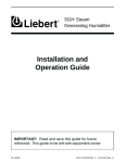
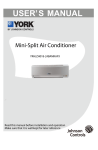
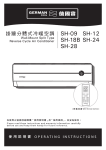
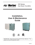
RESDELUX
Steam Humidifiers
Installation, Operation,
Maintenance and
Troubleshooting Guide
IMPORTANT: READ AND SAVE THESE INSTRUCTIONS. This
guide to be left with equipment owner.
1505691-B
Table Of Contents
INSTALLATION
1
RECEIVING & UNPACKING EQUIPMENT . . . . . . . . . . . . . . . . . . . . . . . . . . . . . . . . 1
PRE-INSTALLATION CHECKPOINT . . . . . . . . . . . . . . . . . . . . . . . . . . . . . . . . . . . 1
HUMIDIFIER CONFIGURATION. . . . . . . . . . . . . . . . . . . . . . . . . . . . . . . . . . . . . . 1
LOCATION & MOUNTING . . . . . . . . . . . . . . . . . . . . . . . . . . . . . . . . . . . . . . . . . 1
HUMIDIFIERS . . . . . . . . . . . . . . . . . . . . . . . . . . . . . . . . . . . . . . . . . . . . . 1
STEAM DISTRIBUTOR NOZZLE (in duct location) . . . . . . . . . . . . . . . . . . . . . . . . . . 2
STEAM HOSE INSTALLATION. . . . . . . . . . . . . . . . . . . . . . . . . . . . . . . . . . . . . 3
CONDENSATE HOSE (supplied) . . . . . . . . . . . . . . . . . . . . . . . . . . . . . . . . . . . . 3
BLOWER PACK CONNECTION . . . . . . . . . . . . . . . . . . . . . . . . . . . . . . . . . . . . 3
CABINET MOUNTING THE BLOWER PACK . . . . . . . . . . . . . . . . . . . . . . . . . . . . 3
REMOTE MOUNTING THE BLOWER PACK . . . . . . . . . . . . . . . . . . . . . . . . . . . . 4
PLUMBING . . . . . . . . . . . . . . . . . . . . . . . . . . . . . . . . . . . . . . . . . . . . . . . . . 5
WATER SUPPLY LINE . . . . . . . . . . . . . . . . . . . . . . . . . . . . . . . . . . . . . . . . . 5
DRAIN LINE. . . . . . . . . . . . . . . . . . . . . . . . . . . . . . . . . . . . . . . . . . . . . . . 5
ELECTRICAL. . . . . . . . . . . . . . . . . . . . . . . . . . . . . . . . . . . . . . . . . . . . . . . . 6
ELECTRICAL REQUIREMENTS FOR PERMANENTLY CONNECTED RESDELUX . . . . . . . . . 6
ELECTRICAL REQUIREMENTS FOR THE CORD CONNECTED MODEL RESDELUX/C . . . . . . 6
LOW VOLTAGE CONTROL WIRING AND INSTALLATION . . . . . . . . . . . . . . . . . . . . . . 6
CONTROL WIRING . . . . . . . . . . . . . . . . . . . . . . . . . . . . . . . . . . . . . . . . 6
CONTROL INSTALLATION . . . . . . . . . . . . . . . . . . . . . . . . . . . . . . . . . . . . 7
OPERATION
7
INTRODUCTION . . . . . . . . . . . . . . . . . . . . . . . . . . . . . . . . . . . . . . . . . . . . . . 7
RESDELUX OPERATION . . . . . . . . . . . . . . . . . . . . . . . . . . . . . . . . . . . . . . . . . 7
MANUAL CAPACITY ADJUSTMENT . . . . . . . . . . . . . . . . . . . . . . . . . . . . . . . . . 8
OTHER POTENTIOMETERS . . . . . . . . . . . . . . . . . . . . . . . . . . . . . . . . . . . . . 8
MAINTENANCE
8
STEAM CYLINDER . . . . . . . . . . . . . . . . . . . . . . . . . . . . . . . . . . . . . . . . . . . . 8
WHEN TO REPLACE THE STEAM CYLINDER . . . . . . . . . . . . . . . . . . . . . . . . . . . . 8
HOW TO REMOVE THE STEAM CYLINDER . . . . . . . . . . . . . . . . . . . . . . . . . . . . . 9
HOW TO INSTALL THE REPLACEMENT CYLINDER . . . . . . . . . . . . . . . . . . . . . . . . 9
MANDATORY CLEANING OF THE DRAIN VALVE . . . . . . . . . . . . . . . . . . . . . . . . . . . 10
EXTENDED SHUTDOWN . . . . . . . . . . . . . . . . . . . . . . . . . . . . . . . . . . . . . . . . 10
TROUBLESHOOTING
11
DIAGNOSTIC PROCEDURES - TROUBLESHOOTING . . . . . . . . . . . . . . . . . . . . . . . . . 11
PROCEDURES AND TERMS USED IN DIAGNOSING . . . . . . . . . . . . . . . . . . . . . . . . . 12
PRINCIPLE OF OPERATION . . . . . . . . . . . . . . . . . . . . . . . . . . . . . . . . . . . . . 12
FILL RATE . . . . . . . . . . . . . . . . . . . . . . . . . . . . . . . . . . . . . . . . . . . . . . . 12
DRAIN TIME . . . . . . . . . . . . . . . . . . . . . . . . . . . . . . . . . . . . . . . . . . . . . . 12
RATED AMPERS . . . . . . . . . . . . . . . . . . . . . . . . . . . . . . . . . . . . . . . . . . . 12
SHORT CYCLING . . . . . . . . . . . . . . . . . . . . . . . . . . . . . . . . . . . . . . . . . . . 12
FOAMING . . . . . . . . . . . . . . . . . . . . . . . . . . . . . . . . . . . . . . . . . . . . . . . 12
BACKPRESSURE . . . . . . . . . . . . . . . . . . . . . . . . . . . . . . . . . . . . . . . . . . . 12
MONITORED LEG. . . . . . . . . . . . . . . . . . . . . . . . . . . . . . . . . . . . . . . . . . . 12
RESDELUX WIRING DIAGRAM . . . . . . . . . . . . . . . . . . . . . . . . . . . . . . . . . . . . . 13
SUGGESTED WIRING INTERFACE FOR FAN CONTROL . . . . . . . . . . . . . . . . . . . . . . . 14
SPARE PARTS LIST AND EXPLODED VIEW . . . . . . . . . . . . . . . . . . . . . . . . . . . . 15-16
PERIODIC MAINTENANCE CHECKLIST . . . . . . . . . . . . . . . . . . . . . . . . . . . . . . . . 17
HUMIDIFIER CONFIGURATION
INSTALLATION
To avoid any danger, never operate the
humidifier with a door off.
RECEIVING & UNPACKING EQUIPMENT
1.
Check packing slip to ensure ALL material has
been delivered.
2.
All material shortages are to be reported to
NORTEC within 48 hours from receipt of goods.
NORTEC assumes no responsibility for any
material shortages beyond this period.
3.
Inspect shipping boxes for damage and note on
shipping waybill accordingly.
4.
After unpacking, inspect equipment for damage
and if damage is found, notify the shipper
promptly.
5.
All NORTEC products are shipped on an F.O.B.
factory basis. Any and all damage, breakage or
loss claims are to be made directly to the
shipping company.
To open the door, use the key to unlock, lift door
up slightly and pull door forward.
LOCATION & MOUNTING
HUMIDIFIERS
RESDELUX Series humidifiers are designed to
mount on a suitable wall or vertical surface. Do not sit
on the floor due to additional clearances required for
plumbing, electrical, and control access holes. The
clearance dimensions shown in this manual are for
reference only and are the minimum required for
maintenance of the humidifier. Local and National
Codes should be consulted prior to final location and
installation of the humidifier. Walter Meier (NORTEC)
does not accept responsibility for installation code
violations.
PRE-INSTALLATION CHECKPOINT
1.
Ensure that available voltage and phase
corresponds with humidifier voltage and phase
as indicated on humidifier’s nameplate label.
2.
Ensure that the dedicated external disconnect
switch is of sufficient size to handle the rated
amps as indicated on the nameplate label. Refer
to local codes.
3.
1.
Location of the humidifier should be below and
as close as possible to the steam distributor
location or blower pack. Net output will be
reduced as a result of heat loss through long
steam hose.
2.
See Figure #2 for front clearance requirements
for access during installation, maintenance and
troubleshooting.
Figure #2
Clearance Requirements
Report any discrepancy immediately.
Wall
Figure #1
RESDELUX Series Humidifier
Condensate
Return
Steam
Outlet
NOTE: Local and national
codes may deviate. Please
consult applicable codes
for clearance requirements
3.
Where possible, mount humidifier at a height
convenient for servicing.
4.
To mount the humidifier use two #8 screws, 2”
long, and secure into a standard 2”X4” wood
stud or equivalent structure.
Nameplate
Label
Drain
PowerAnd
Control
Wiring
Water
Supply
-1-
Min. 36"
Frontal
Clearance
Figure #3
Wall Mounting Detail
nozzle will have to be mounted from the inside of
the duct. Remove internal insulation material if
necessary. (See Figure #5).
Figure #5
Steam Distribution Nozzle Mounting Arrangement
Wall
0.6”
(1.6 cm)
Fasten Humidifier To
Wall Using Screws 2” long
(2) supplied by other
12.1” A(30.7cm)
5. Make sure humidifier is level.
6. DO NOT mount humidifier on hot surfaces.
3. When the steam distribution nozzle is located
above the top surface of the humidifier: The
nozzle must be at least 1 ft (305 mm) above the
top surface of the humidifier. Locate the steam
hose so that it slopes at an angle of at least 20°
(Figure #6).
7. DO NOT mount humidifiers in an area where
freezing may occur.
8. DO NOT mount humidifiers on a vibrating surface.
10. DO NOT mount the humidifier to a duct or plenum.
Figure #6
Steam Plumbing Arrangement Above Humidifier
STEAM DISTRIBUTOR NOZZLE (in duct location)
1. When installing the steam distribution nozzle of
the RESDELUX humidifier it must be located in
the supply duct at least 4 feet from any
obstructions such as bends, fans, filters, etc. to
prevent wetting (see figure #4).
min. 10º
12” (300 mm)
Figure #4
Steam Distributor Nozzle in Duct Location
min. 10º
12 Rmi
” (3 n.
00
m
12” min. (300 mm)
m)
min. 2º
m)
0m
6”
15
n(
mi
To be 2” (50mm) longer
then duct static pressure
or minimum.
Nortec
Humidifier
NHB, NHP, NHMC,
RESDELUX ONLY
Min. 12”
4. Steam distribution nozzle below top surface of
humidifier: The steam hose must first rise to the
minimum height of 1 ft (305 mm) above the top
surface of the humidifier and thereafter slope a
minimum 5° in a uniform manner toward the
nozzle. A separate drain line must be provided for
condensate that collects at the steam distribution
nozzle (Figure #7).
2. The steam distribution nozzle can be mounted in
the bottom wall or on the vertical walls of the duct.
If the duct wall is more than 3/4" (20 mm) thick, the
-2-
Figure #7
Steam Plumbing Arrangement Below Humidifier
12” (300 mm)
12
” (3
00
mm
)
12” min. (300 mm)
min. 10º
Nortec Humidifiers
All Models
m)
mi
min. 10º
m
in. 0 m
Rm ” (30
12
)
12” (300 mm)
min. 2º
BLOWER PACK CONNECTION
The RESDELUX humidifier can be purchased with
an optional blower pack for direct room humidification.
The blower pack is field installed on the RESDELUX
humidifier cabinet or located remote from the
RESDELUX humidifier.
Nortec Humidifiers
All Models
12” min. (300 mm)
min. 20 %
m)
0m
6”
n
mi
(15
m)
The blower pack is powered directly from the
RESDELUX control board. It cannot be powered
separately.
0m
15
(
in
”m
6
On a call for humidity, blower fans are powered
and remain powered for about two minutes after steam
production is interrupted.
STEAM HOSE INSTALLATION
1.
2.
Use wall clips (p/n 158-5001) to support the
steam and condensate hoses and maintain 1”
clearance from the wall. The connection can also
be made with ¾” copper pipe with 1” thermal
insulation rated for 215°F (101°C).
Under normal circumstances, when the steam
distribution nozzle is above the top surface of the
humidifier, the condensate hose is routed back to the
top of the humidifier and fed through the opening
provided to the fill cup. Cut the ends diagonally and
simply insert ½" in the appropriate hole in the top of
the humidifier. Install a 3/8” copper tubing trap at the
lowest point in the condensate system. Connect to the
hose with a clamp Figure #6.
0m
min. 20 %
4.
CONDENSATE HOSE (supplied)
15
n(
To be 2” (50mm) longer
then duct static pressure
or minimum.
Avoid condensate traps in the hose, see Figure
#8.
min. 10º
min. 2º
6”
3.
The length of the steam hose must not exceed 4’
(1.2m).
Cabinet Mounting of the Blower Pack
It must not be restricted in any way (i.e. - a kink
resulting from a short radius bend).
The RESDELUX blower pack comes with a basic
hardware kit. The kit contains all the hardware
required to cabinet mount the blower pack.
Figure #8
Steam Hose Routing
Avoid kinks
NOTE: Mounting of the blower pack must be
performed before the RESDELUX humidifier is
installed and wired.
Avoid Water Traps
Proper
Slope
Gentle
Sweeping
Turns
-3-
1.
Remove the RESDELUX humidifier and blower
pack from their shipping boxes.
2.
Place the RESDELUX humidifier upright on a flat
surface.
3.
Remove the 7/8” knockout on the top of the
RESDELUX humidifier. There are two
knockouts, select the one closest to the large
opening.
switched off at the electrical panel, or that it is
unplugged (RESDELUX/C).
4. Put the power leads from the blower pack through
this opening as you position the blower pack on
top of the RESDELUX humidifier
3. Find a suitable location for mounting the remote
blower pack. The surface should be flat with
adequate clearances for the top, side, and front:
5. Push the blower pack forward until the locating
tabs on the bottom of the blower pack with slots in
the top of the RESDELUX push forward to engage.
Table #1
Clearances of Remote Mounted Blower Pack
6. Use two Phillips screws with star washers in the
Blower Pack screw support tabs to secure to the
RESDELUX unit.
7. Remove the front door and service cover from the
RESDELUX humidifier.
8. Connect the power leads for the blower pack to
terminal P7 on the RESDELUX control board
located next to the capacity adjustment
potentiometer.
Minimum Ceiling
Clearance
inches (cm)
Minimum Side
Clearance
inches (cm)
Minimum frontal
Clearance
inches (cm)
18” (45)
18” (45)
60” (150)
4. Minimum slope of steam hose is 20°. Steam lines
longer than 5 ft require condensate trap installation
(see Figure #6).
9. Use the short piece of steam hose and hose
clamps supplied with the basic hardware kit to
connect the steam cylinder to the blower pack
steam distributor.
5. RESDELUX blower pack has two teardrop (or
keyhole) openings on the back of the cabinet for
mounting purposes. They are located 8 ¼” apart,
and 1” from the top of the blower pack cabinet.
Installation of the blower pack is now complete.
For instructions on mounting the RESDELUX
humidifier please see the location and mounting
section.
6. Measure the screw locations and use two #8
screws, 2” long. The screws should be anchored in
a standard 2” x 4” wood stud or equivalent to
ensure adequate support of the blower pack and
connecting steam hose.
Figure #9
Blower Pack Cabinet Assembly
7. Remove the 7/8” knockout on the top of the
RESDELUX humidifier and insert the closed finger
grommet into the opening.
8. Put the power leads from the blower pack through
this opening. If the wire leads are not long enough
field splice the additional requirement, or get a wire
extension kit (P/N 1502326) available from
NORTEC.
Figure #10
Steam Absorption Distances
Steam absorption space size in inches for ambient humidity
30% RH, room temperature and selected steam outputs of
RESDELUX humidifier.
H
Remote Mounting of the Blower Pack
W
F
1. The remote mounted blower pack should be
located at least 7’ off the floor to prevent the
discharged steam from coming in contact with
pedestrian traffic or any obstruction.
0”
2. When installing the remote blower pack, ensure
the primary voltage to the RESDELUX has been
Steam Output
-4-
F
W
H
4 lbs/hr
36"
12"
12"
6 lbs/hr
42"
16"
18"
8 lbs/hr
48"
18"
18"
NOTE: Improper wiring could damage the blower
pack or RESDELUX PCB.
9.
Remove the front door and service cover from
the RESDELUX humidifier.
10.
Connect the power leads for the blower pack to
terminal P7 on the RESDELUX control board
located next to the capacity adjustment
potentiometer.
11.
more corrosive. Some hardware changes may
be required, at the time of order or in the field.
3.
DO NOT supply hot water to the humidifier.
Minerals will adhere more easily to surfaces and
the fill valve’s small flow regulating orifice could
become plugged.
4.
ALWAYS supply and install a shut off valve in
the water supply line dedicated to the humidifier
to facilitate servicing. Use ½" O.D. copper to
within 4 feet of the humidifier. Reduce copper to
1/4" O.D. and connect to the factory-supplied
1/4" olive compression fitting under the
humidifier.
Replace the electrical service cover and front
door.
Once the power is restored the RESDELUX
humidifier is ready for service.
Figure #12
Drain Pump (if necessary)
PLUMBING
For humidifiers installed in some cities including
the City of Los Angeles:
Humidifier
A city-approved spring-loaded double ball CHECK
VALVE must be supplied and installed by contractor
on each of the potable water inlets to each humidifier.
Recommended valve manufacturer: Watts Regulator
phone number 508-688-1811. Size: Depending on
supply line 1/4", 3/8" or ½" NPT inlet and outlet.
Model: #7.
Drain Canal
Drain Line
Line
All water supply and drain line connections should
be installed in accordance with local plumbing codes.
Floor
Surface
WATER SUPPLY LINE
DRAIN LINE
1.
The Humidifier is intended to operate on potable
(cold) tap water.
2.
If the raw water is very hard, NORTEC can
provide longer cylinder life on softened water;
however, softened water is more conductive and
Figure #11
Drain Connection
1.
The humidifier is equipped with a 7/8" O.D.
unthreaded horizontal drain outlet from the drain
canal on the bottom of the humidifier. A
field-supplied funnel or reducer(see Figure #11)
is recommended. It will prevent backup in the
drain pan and in the cylinder due to partially
blocked or poorly installed drain lines.
2.
The drain line should not drain into a sink used
frequently by personnel, or where plumbing
codes prohibit it. Route to a floor drain or
equivalent for safety reasons, since drain water
from humidifier can be very hot.
3.
Keep drain lines as short as possible. Keep
drain lines sloped down, not level and not up
since low spots in drain lines will accumulate
sediment and cause backup. The drain line
should be 7/8" O.D. copper pipe or larger. Do
not use plastic pipe for drain lines.
4.
Each drain line from these humidifiers must be
routed without dips or sags to terminate above
NOTE: Steam hose should not reach bottom of the funnel.
ClampAnd
7/8" I.D. Hose
Factory Supplied
Air Gap
7/8" O.D. Copper
Pipe Or 7/8" I.D.
Hose (Not Supplied)
142-9527
Pump
Drain Canal
Copper Reducer To
ServeAs Funnel
Drain (By Others)
(Min. 11/4” OD)
-5-
current) across terminals 1 and 2 on the low voltage
control terminal.
Control Installation
1.
Wall Humidistat: Mount any wall humidistat
(control or high limit) over the standard electrical
box at a height similar to a typical thermostat.
Any wall humidistat should be in a location
representative of overall space being humidified
and not in the path of the blower pack or air
supply grille. Do not mount on an outside wall
where temperature fluctuation can affect the
control response.
2.
Duct Humidistat: Mount the duct humidistat In a
location representative of overall air humidity,
(usually the return duct). Do not mount it directly
in front of the steam distributor or in a turbulent
or mixing zone. Mount it where the air’s humidity
and temperature are uniform and representative
of spaces being humidified.
3.
High Limit Duct Stat: Mount the duct high limit
humidistat downstream of the steam distributors
far enough that, under normal humidity and air
flow conditions, steam will have been fully
absorbed (typically at least 10 feet). It must be
located to sense high humidity only when
uniform and representative air is over-humidified
or approaching saturation.
4.
Duct Air Proving Switch: Mount the duct
air-proving switch so that it is able to sense air
flow or lack of it. Wire it to close when air flow is
sensed and open when air flow fails.
5.
Check operation of all on/off controls before
starting the humidifier.
Caution: This is the “common” wire from the
transformer that is connected to the ground. It will
short on/off control loop if it touches a grounded
metal surface.
A - Wall or Duct Mounted Control On/Off
Humidistat: Wired to close when there is a drop in
humidity and open when the setpoint is reached. Set
to desired % RH.
B - Duct Mounted Safety High Limit On/Off
Humidistat (if used): Wired to close when there is a
drop in humidity and open when the safety setpoint is
reached. Set to approximately 85% RH as a safety to
help prevent saturation and wetting in the duct (not
required when using blower pack kit).
C - Duct Mounted Safety Air-Proving On/Off
Switch (if used): Wired to close when sensing air flow
and open when no air flow is sensed. Used as a
safety to prevent saturation of the duct when there is
no air flow (not required when using blower pack kit).
Figure #14
External Wiring Of On/Off Controls
A
B
C
External
Internal
1.
1
2
OPERATION
NORTEC offers various versions of A, B and C
to suit each application. In general, A is
essential for in space applications, C is essential
for induct applications, whereas B is highly
recommended in ducted applications.
2.
Field wiring from the humidistat to the humidifier
and between devices should be a minimum of 18
AWG and kept as short as possible.
3.
Low voltage control terminal strips are provided
in the electrical compartment. Internal sides are
factory wired. External sides are for field wiring.
(See Figure #14).
4.
Note: For wiring interface with a fan, see wiring
diagram provided on page 13. Steam humidifier will
turn on fan when increase in humidity is required.
INTRODUCTION
The NORTEC RESDELUX humidifier is designed
to provide clean steam humidification at an economical
price. It utilizes NORTEC’s patented electronic
Auto-Adaptive internal control system for high
efficiency and low waste of water and electricity.
RESDELUX OPERATION
When the humidifier is first turned on, the
controller starts with a self test procedure, which takes
about 10 seconds. The test consists of activating for a
short time the drain valve, fill valve, and power relays.
The sound of the working solenoids is an indication of
Each humidifier is supplied with a wiring diagram
inside.
-7-
A flashing yellow light indicates a fault of the
humidifier and the controller shuts off the humidifier.
Please refer to troubleshooting section.
valves operation. Green and yellow lights flash during
this time.
If there is no call for humidity, the humidifier is
standing by and green light flashes. When control loop
is closed, the green light is steady on and the
humidifier starts its operation. The controller waits 10
seconds before energizing the on-board relays. When
the relays energize, heating voltage is delivered to the
cylinder. After a 30 second delay, the fill valve is
activated (if the output from the cylinder is below 100
%). If controller detects increase of amperage above
allowed range, the unit will activate drain valve for 2
seconds.
For periods of time with no call for humidity, longer
than 2 days, the humidifier automatically drains water
from cylinder.
MANUAL CAPACITY ADJUSTMENT
The RESDELUX humidifier is rated in lbs/hr of
steam output capacity. Set to 100%, it will operate at
full output until the humidistat has sensed that the
humidity has reached setpoint, it will then stop when
the control circuit 1-2 is interrupted. See Figure #13.
During operation, the controller measures the rate
at which water is converted to steam and thus the
mineral content of water inside the cylinder. When this
rate exceeds the design optimum, a drain of the
cylinder takes place. The amount of water drained is
just enough to keep the contained water at design
levels.
If the humidifier is oversized, the humidistat will be
quickly satisfied (less then 10 minutes) and stop the
humidifier. As the humidity level drops the humidistat
starts the humidifier again. It is quickly satisfied and
stops again. The resultant short-cycling can be easily
overcome. A manual capacity adjustment
potentiometer is provided on the RESDELUX main PC
board to increase the runtime to about 15 minutes. It
is marked “CAPACITY ADJUSTMENT” and is
adjustable from 25 to 100% of operating rating.
During start up, when mineral content in the water
is low, water will reach the top of the cylinder at which
point the yellow indicator light will come on. This is
normal operation with a fresh cylinder. After a period of
time the water level will drop and the yellow light will
turn off.
OTHER POTENTIOMETERS
Do not adjust any other potentiometers on the PC
board. They are factory-set and not to be adjusted in
the field.
High water level in the cylinder also indicates that
the cylinder is near the end of its service life as
electrodes become coated with minerals. The yellow
light coming on more often would be the first indication
of approaching the end of the cylinder life.
MAINTENANCE
As with all automatic and mechanical devices,
humidifiers require periodic maintenance and
servicingeither by the user or competent service
personnel to provide continued customer
satisfaction, longer equipment life and reduction in
customer cost.
Figure #15
Operation Schematic
CONDENSATE RETURN
(OPTIONAL)
FILL
CUP
1
2
3
1” AIR
GAP
WARNING! DISCONNECT THE UNIT FROM
THE POWER SUPPLY BEFORE SERVICING.
The plumbing and electrical compartments contain
high voltage components and wiring. The access door
is equipped with a lock. Access should be limited to
authorized personnel only.
STEAM HOSE
ELECTRODES
1. INLET CHAMBER
2. FILL CHAMBER
3. WATER OVERFLOW
CHAMBER (SAFETY DRAIN
IN CASE OF FILL VALVE/
CONTROL BOARD FAILURE)
Note: Review periodic maintenance. Checklist on page
16.
CYLINDER
STEAM CYLINDER
STRAINER
FILL
VALVE
TAP WATER
SUPPLY
DRAIN
VALVE
WHEN TO REPLACE THE STEAM CYLINDER
DRAIN
PAN
After a period of operation (not on initial startup),
the water level will approach the top of the cylinder.
DRAIN
CONNECTION
DRAIN CANAL
(OPEN TO ATMOSPHERE)
-8-
(Life varies from 500 to 2000 operating hours, as
illustrated in Figure #16.)
cylinder or quote the unit’s serial number, model and
voltage located on the spec label (nameplate).
The RESDELUX control board constantly monitors
unit performance and will shut down the humidifier and
alert the customer to change the cylinder. The yellow
light will flash 4 times in sequence.
1.
Turn off the water supply to the unit.
2.
The used cylinder must be drained completely
before removal. If the water has just been
boiling, allow it to cool before draining. Push the
ON/OFF/DRAIN switch to the MANUAL DRAIN
position. Leave it in this position just long
enough to drain the cylinder (usually not longer
than 3 minutes).
3.
When completely drained, push the main
ON/OFF/DRAIN switch back to the OFF position.
4.
Once drained, disconnect all power supplies to
the unit.
5.
Open the front cover door.
6.
Cylinder plugs are attached to the primary
voltage cylinder wires. Remove cylinder plugs
from cylinder pins by pulling vertically.
7.
Using a slotted screwdriver, loosen the steam
hose clamp(s) and pull the steam hose off the
cylinder vertically.
8.
The cylinder is now ready to be lifted out of the
unit. CAUTION: Cylinder and any undrained
water might still be HOT.
9.
Remove the used cylinder as previously
described. NORTEC does not recommend the
use of any acid solutions to clean the used
cylinder. Always replace a used cylinder.
Figure #16
Water Conditions vs. Cylinder Life
Capacity Adjustment Setting
100%
50%
25%
30
500
20
200
10
CaCO3 mg/L (ppm)
Grains of Hardness
400
100
5
500
1000
2000
4000
Cylinder Life Expectancy
(average operating hours)
8000
HOW TO REMOVE THE STEAM CYLINDER
It is advisable to keep a spare cylinder in stock
throughout the humidification season. When ordering
a replacement steam cylinder, always quote the three
or five digit model number on the label applied to the
Figure #17
Cylinder Replacement
HOW TO INSTALL THE REPLACEMENT CYLINDER
1.
Reverse procedure should be followed to install
a new cylinder. Main power supply to the unit
must be disconnected until the cylinder is
completely installed and reconnected.
2.
The cylinder plug wires are color-coded in
accordance with colored dots beside the
electrode pins on the top of the cylinder.
Figure #18
Reassembly Of The Drain Valve And Fill Valve
Actuator
Male Slip-on
Connection Tabs
Plunger
Spring
Sleeve
Holding Coil
-9-
12. Push the two slip-on terminals back onto the two
tabs on the coil. The terminals, although not
identical, are reversible.
3. This color-coding must be adhered to when
replacing cylinder plugs on pins.
4. The electrode plug with the orange wire always
goes on the single pin surrounded by a plastic
shoulder.
WARNING: To prevent the possibility of electrical
shock the green ground wire must be reinstalled
before power is restored.
5. Ensure that cylinder plugs fit snugly on the pins.
EXTENDED SHUTDOWN
6. If a cylinder plug becomes loose the cylinder
harness must be replaced (P/N 158-1305 see
parts list).
Before disconnecting power to the humidifier at
the end of humidification season, ALWAYS DRAIN the
cylinder first. Otherwise, the electrodes are subject to
harmful corrosion which shortens cylinder life. Do
NOT leave the switch in the DRAIN position
indefinitely as the drain coil could burn out. Leave the
switch in the OFF position and “open” the main
external fused disconnect to stop power to the
humidifier. Close the shut off valve in the water supply
line feeding the humidifier. Lock the cabinet door(s) to
prevent unauthorized tampering. All doors are factory
supplied with keyed locks. DO NOT LEAVE THE KEY
IN THE LOCK. ACCESS SHOULD BE LIMITED TO
AUTHORIZED PERSONNEL ONLY.
MANDATORY CLEANING OF THE DRAIN
VALVE
Always clean the drain valve before installing a
new cylinder since the valve port may be as dirty as
the used cylinder.
1. Note the ring terminal for drain valve green ground
wire is sandwiched between the drain valve body
and drain pan.
2. Remove the two screws securing drain valve body
to the drain pan. Disconnect the two slip-on
terminals from the two tabs on the (24 Vac) drain
valve coil.
3. Remove the hose clip and hose connection from
drain valve body.
4. The drain valve assembly is now free to be taken
to a sink for disassembly and cleaning.
5. Remove the snap-fit red cap from the coil
assembly and slide coil off the actuator.
6. Loosen the actuator with a wrench and unscrew
from the plastic valve body.
7. Clean the exposed core, spring and plastic drain
valve port.
8. The tapered end of the spring must be installed
toward the solenoid. Reassemble and tighten the
actuator 1/4 turn past hand-tight.
9. Clean out the end of the hose, then reconnect it to
the drain valve body with the clamp.
10. Inspect the o-ring to make sure it is in good
condition.
11. Fit mounting screws through the drain valve body,
one through the ring terminal on green ground
wire.
- 10 -
is provided in the section titled OPERATION. For
a more detailed understanding please contact
your NORTEC representative.
TROUBLESHOOTING
PLEASE READ THIS SECTION BEFORE
REFERENCING SPECIFIC DIAGNOSTIC
MESSAGES.
1.
Ensure the installation detail conforms with the
recommendations contained in the Installation
section of this manual.
2.
Understanding the Principle of Operation is an
asset when troubleshooting. A basic description
3.
When contacting your local representative or
NORTEC for troubleshooting assistance, please
ensure the serial number has been obtained for
reference purposes.
4.
Whenever the troubleshooting steps indicate a
problem with the main PCB, first check all
connections at the main control board.
DIAGNOSTIC PROCEDURES - TROUBLESHOOTING
The RESDELUX controller provides a number of messages to simplify troubleshooting procedures. The following
table presents fault messages displayed by the controller, their meaning and possible corrective actions. Refer to the
following section for detailed information about terms used in the table.
Table #4 - Troubleshooting Guide
Unit Status Lamp
Yellow
Green
Symptom
Corrective actions
On
On
Maximum water level This usually happens on initial start-up after replacing the cylinder
inside cylinder.
(normal).
Water is concentrated with minerals inside the cylinder.
Let unit run, yellow light will disappear when the unit is at full
output. This may take a day or two.
Off
Off
No power to the
board.
Check for main power supply fault.
Turn power switch to ‘Drain’ position. If drain valve is activated
(sound of solenoid), check connection to the board or board itself.
When no sound present, check fuse (replace with 1.5A if needed),
transformer (voltage should be present between fuse holder and
ground screw).
1 flash
sequence
Off
Over current.
Operating amperage
exceeded 130% of
rated amps. Water is
drained from the
cylinder (drain valve
on for 10 min.).
Check drain valve operation, drain time, possible drain restrictions.
Check if fill valve leaks (not holding supply water).
Back pressure may also cause very conductive water conditions.
Was the humidifier short cycling?
Check for short cycling.
2 flashes in Off
sequence
No current
detection for 30
minutes with
continuous call for
humidity.
Check water level in the cylinder - should be more than ¼ full. If not
check fill rate, 24 VAC voltage on fill valve terminals (unit must be
on with call for humidity - green light steady on). Verify fresh water
supply to the humidifier. Leaking drain valve can be at fault
(minerals blocking the plunger).
If cylinder is more than ¼ full, check primary power, connections to
the cylinder, continuity of wires to cylinder.
Are power wires connected to proper terminals on the cylinder?
(Color coding)
Possibly wrong cylinder type.
Low water conductivity.
4 flashes in Off
sequence
End of cylinder life change cylinder.
Check water level in the cylinder, should be about ¾ full.
Check for foaming if water level lower or cylinder life shorter than
expected.
Change cylinder, clean drain valve.
- 11 -
SHORT CYCLING
PROCEDURES AND TERMS USED IN
DIAGNOSING
When the ‘on time’ of the humidifier is less than
ten minutes upon a call for humidity. To correct short
cycling, all humidifiers have a capacity adjustment
which allows the output of the humidifier to be reduced
as low as 25% of rated output, thus extending the ‘on
time’ required to maintain output. Excessive short
cycling may cause higher water conductivity (mineral
content) than designed for the unit.
PRINCIPLE OF OPERATION
The conductivity of the water within the cylinder
must be controlled in order for the humidifier to
function properly. The fill and drain rates must be
maintained. Filling too quickly can cause over-amping
and automatic shutdown or blown fuses. Filling too
slowly can cause insufficient steam output and
foaming. Water supply pressure should be between
25 and 110 psig. Draining too slowly can cause
over-concentration and malfunction due to foaming.
These are just some examples of what can go wrong if
the fill and drain rates are not maintained.
FOAMING
A phenomenon which can occur in water when
impurities, already in the water, reach an excess
concentration as result of boiling away pure water and
the continued boiling action agitating the contained
water. The humidifier electronics are designed to
prevent this occurrence although in extreme cases
water will foam with little concentration, making it
necessary to have the drain time of the water,
contained in the cylinder, increased. Foaming is
normally caused by short cycling, a restricted drain, or
back pressure. The foam, generated in these
instances, is conductive and may lead to a false full
cylinder indication if the level of the foam approaches
the top of the cylinder.
FILL RATE
Fill rates of suspect units should be checked. Fill
rates should measure nominally at 1" to 1-1/2" of
vertical rise in water level in the cylinder in one minute.
Clogged fill valve will cause lower fill rate. The fill
valve strainer is removable and can be cleaned.
DRAIN TIME
BACKPRESSURE
Manual drain time of a half full cylinder takes
approximately 25 seconds.
Restriction of steam flow caused by improperly
sloped steam lines, elbows changing the direction of
the steam flow from horizontal to vertical without a
condensate drain leg, and any plumbing detail allowing
the accumulation of condensate.
If time measurements are longer, repeat with the
external drain disconnected (and draining into a pail)
to verify that the external drain is impeding flow. If it
still does not drain, check for a clogged strainer or
drain.
MONITORED LEG
A clogged strainer or drain valve will cause
shortened cylinder life. Determine what caused the
strainer or drain valve to clog in the first place.
Refers to the primary wire, to the cylinder, which
loops through the current sensing device on the main
PCB. This wire is terminated at the red cylinder plug
at the cylinder.
Do not assume that if a strainer and/or drain valve
is clogged that it is to blame. If the external drain has
been impeding flow then waste accumulates resulting
in a clogged strainer or clogged drain.
Clean the drain valve and install a fresh cylinder.
Then measure the manual drain time with and without
the external drain connected. Is the external drain
impeding flow? NORTEC recommends an open
external drain line. See the Installation section of this
manual.
RATED AMPERS
This refers to amps listed on the humidifier
specification label.
- 12 -
- 13 -
- 14 -
SPARE PARTS LIST AND EXPLODED VIEW - RESDELUX
Item Number
Part Number
Description
1
151-9002
Cylinder type 202
2
158-1820
Steam distributor kit
3
153-5062
Steam distributor
4
158-1830
Steam blower pack
5
158-1821
Steam Hose 4’ long
6
158-7104
Cabinet front door
7
185-3104
Lock assembly with keys
8
145-6000
Drain valve complete
8a
145-5002
Screw Drain Valve
9
132-6002
Drain valve coil assembly
10
132-6004
Drain valve o-ring
11
131-3244
Fill valve assembly
11a
145-5000
Fill valve gasket only
11b
145-5004
Fill valve screw
12
149-5072
Brass fitting with gasket
12a
132-6129
Elbow
13
158-1450
Fill cup assembly kit with hoses and clamps
13a
142-1050
Fill cup
13b
132-8850
Condensate hose (small dia.)
13c
132-8860
Condensate hose (medium dia.)
13d
132-5023
Clamp small house
13e
132-5035
Clamp medium hose
14
132-1216
Drain canal round
14a
132-5064
Screw drain canal
15
163-1026
Gasket for round drain canal
16
158-3511
Power control board (provide unit serial number when ordering).
17
150-1491
Transformer 120/24 Vac
18
158-3126
Fuse 1.5A
19
132-3097
On/Off/Drain switch
20
158-1309
Wire harness - drain & fill valves
Wire harness - cylinder, complete
21
158-1305
21a
135-4012R
Cylinder plug RED
21b
135-4012B
Cylinder plug BLACK
21c
132-4012W
High water sensor pin
22
158-1311
Power Supply
23
158-1312
Blower Fan Assembly
24
150-2326
Wire extension for blower pack
Not Shown
132-8810
Steam Hose (Specify Length)
Not Shown
158-5001
Steam and condensate hose support bracket (Specify Quantity)
Not Shown
132-8841
Condensate Line (Specify Length)
- 15 -
4
23
22
24
5
2
3
21a
17 16
18 21b 21c
1
7
13a
13d
13e
20
8a
13b
10
19
13c
11b
15
11a
14
12 12a
14a
- 16 -
11
8
9
6
PERIODIC MAINTENANCE CHECKLIST
PREVENTIVE MAINTENANCE AND SERVICE CHECK LIST FOR NORTEC’S RESDELUX
Customer ______________________________________________________________
Address ____________________________________________________________________________
Equipment Location ________________________ Serial # _______________________
Date Last Inspected _________________ Date of this Inspection __________________
Inspected By ________________________________________________________________________
Humidifier ___________________________________________________________________________
Company Name _____________________________________________________________________
Model Number ___________________________________________________________
Inspect, Check, Clean, and Adjust all items listed.
STEAM GENERATORS...................................................................................................r
Replace cylinder, check drain valve, and fill valve.
SUMP AND DRAIN LINES..................................................................................................................r
Clean sump and drain lines and make sure drains and drain lines are free of restrictions.
Check for leaks and proper water level.
STEAM DISTRIBUTION.......................................................................................................................r
Check steam line sloping, no leaks, no condensate around blower pack or distribution
nozzle.
CONTROLS......................................................................................................................r
Humidistat, check for proper operation. All electrical terminals for tightness. Disconnect
switch, check operation.
KEY:
r - Okay
r - Needs Additional Service
r - Repair or Replace
Remarks: ______________________________________________________________
_____________________________________________________________________________________
_____________________________________________________________________________________
_____________________________________________________________________________________
- 17 -
LIMITED WARRANTY
Walter Meier Inc. and/or Walter Meier Ltd. (hereinafter collectively referred to as THE
COMPANY), warrant for a period of two years from date of shipment, that THE COMPANY’s
manufactured and assembled products, not otherwise expressly warranted (with the exception of
the cylinder) are free from defects in material and workmanship. No warranty is made against
corrosion, deterioration, or suitability of substituted materials used as a result of compliance with
government regulations.
THE COMPANY’s obligations and liabilities under this warranty are limited to furnishing
replacement parts to the customer, F.O.B. THE COMPANY’s factory, providing the defective part(s)
is returned freight prepaid by the customer. Parts used for repairs are warranted for the balance of
the term of the warranty on the original humidifier or 90 days, whichever is longer.
The warranties set forth herein are in lieu of all other warranties expressed or implied by law.
No liability whatsoever shall be attached to THE COMPANY until said products have been paid for
in full and then said liability shall be limited to the original purchase price for the product. Any
further warranty must be in writing, signed by an officer of THE COMPANY.
THE COMPANY’s limited warranty on accessories, not of Walter Meier’s manufacture, such as
controls, humidistats, pumps, etc. is limited to the warranty of the original equipment manufacturer
from date of original shipment of humidifier.
THE COMPANY makes no warranty and assumes no liability unless the equipment is installed
in strict accordance with a copy of the catalog and installation manual in effect at the date of
purchase and by a contractor approved by THE COMPANY to install such equipment.
THE COMPANY makes no warranty and assumes no liability whatsoever for consequential
damage or damage resulting directly from misapplication, incorrect sizing or lack of proper
maintenance of the equipment.
THE COMPANY retains the right to change the design, specification and performance criteria
of its products without notice or obligation.
Model #:
Serial #:
Cylinder #:
Cylinder Last Replaced:
_________________________
MTH/DAY/YR
_________________________
MTH/DAY/YR
_________________________
MTH/DAY/YR
PRINTED IN CANADA
E6518
Walter Meier (Climate USA) Inc.
826 Proctor Avenue, Ogdensburg, New York 13669
Walter Meier (Climate Canada) Ltd.
2740 Fenton Road, Ottawa, Ontario K1T3T7
Tel: 866 NORTEC 1 Fax: 613 822 7964
[email protected] www.humidity.com