1
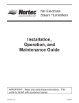
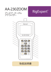
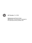
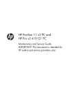
MES Electrode
Steam Humidifiers
Installation, Operation,
Maintenance, Spare Parts, and
Exploded Views Guide
IMPORTANT: Read and save this guide for future reference.
This guide to be left with equipment owner.
Form 08-111
Table of Contents
INSTALLATION
1
RECEIVING EQUIPMENT . . . . . . . . . . . . . . . . . . . . . . . . . . . . . . . . . . . . . . . . . 1
PRINCIPAL OF OPERATION . . . . . . . . . . . . . . . . . . . . . . . . . . . . . . . . . . . . . . . 1
WATER SUPPLY AND PLUMBING . . . . . . . . . . . . . . . . . . . . . . . . . . . . . . . . . . . . 2
WATER CONNECTION . . . . . . . . . . . . . . . . . . . . . . . . . . . . . . . . . . . . . . . . . . 2
START-UP AND OPERATION . . . . . . . . . . . . . . . . . . . . . . . . . . . . . . . . . . . . . . . 2
CAPACITY ADJUSTMENT. . . . . . . . . . . . . . . . . . . . . . . . . . . . . . . . . . . . . . . . . 3
CYLINDER REPLACEMENT. . . . . . . . . . . . . . . . . . . . . . . . . . . . . . . . . . . . . . . . 3
WHEN TO REPLACE THE STEAM CYLINDER
. . . . . . . . . . . . . . . . . . . . . . . . . . . . . 3
REMOVING THE OLD CYLINDER . . . . . . . . . . . . . . . . . . . . . . . . . . . . . . . . . . . . 4
INSTALLING THE NEW CYLINDER . . . . . . . . . . . . . . . . . . . . . . . . . . . . . . . . . . . . 4
MAINTENANCE
4
EXTENDED SHUTDOWN . . . . . . . . . . . . . . . . . . . . . . . . . . . . . . . . . . . . . . . . . 4
TROUBLESHOOTING
4
TERMS USED . . . . . . . . . . . . . . . . . . . . . . . . . . . . . . . . . . . . . . . . . . . . . . . 4
STARTING POINT . . . . . . . . . . . . . . . . . . . . . . . . . . . . . . . . . . . . . . . . . . . . . 5
DIAGNOSTIC PROCEDURES TROUBLE-SHOOTING TIPS . . . . . . . . . . . . . . . . . . . . . . . 7
SOFTWARE REQUIREMENT FOR MODBUS RTU . . . . . . . . . . . . . . . . . . . . . . . . . . . . 8
PHYSICAL DIMENSIONS DIAGRAM . . . . . . . . . . . . . . . . . . . . . . . . . . . . . . . . . . . 11
WIRING DIAGRAM . . . . . . . . . . . . . . . . . . . . . . . . . . . . . . . . . . . . . . . . . . . . 12
SPARE PARTS LIST . . . . . . . . . . . . . . . . . . . . . . . . . . . . . . . . . . . . . . . . . . . 14
EXPLODED VIEWS DIAGRAM . . . . . . . . . . . . . . . . . . . . . . . . . . . . . . . . . . . . . . 15
Figure #1
INSTALLATION
O
p
erS
ati
o
n
c
h
em
RECEIVING EQUIPMENT
CONDENSATE RETURN
(OPTIONAL)
1. Check packing slip to ensure ALL material has
been received.
2. Inspect box for damage and note on shipping
waybill accordingly.
FILL
CUP
1
3. After unpacking, inspect unit for damage and if
damage is found, advise shipper as soon as
possible.
2
3
1” AIR
GAP
STEAM HOSE
ELECTRODES
1. INLET CHAMBER
2. FILL CHAMBER
3. WATER OVERFLOW
CHAMBER (SAFETY DRAIN
IN CASE OF FILL VALVE/
CONTROL BOARD FAILURE)
4. Inspect unit (humidifier) to ensure it is the
correct model, phase, and voltage. If any are
incorrect, advise the factory or your local
representative immediately.
NOTE: All products are shipped on an F.O.B.
factory basis. Any and all damage, loss, or breakage
claims are to be made directly to the shipping
company.
STRAINER
TAP
WATER
SUPPLY
CYLINDER
FILL
VALVE
DRAIN
VALVE
DRAIN
PAN
DRAIN
CONNECTION
DRAIN CANAL
(OPEN TO ATMOSPHERE)
The NORTEC MES-U/MES-P electrode humidifier
is the culmination of many years of research and
development in the electrode humidifier industry. This
unit has been built by skilled craftspeople and
thoroughly tested before shipment and should, if the
following instructions are observed, provide many
years of trouble-free operation.
An electronic timer uses the rate of amp fall to
determine the water level. The objective is to
concentrate current-carrying minerals in the cylinder
so that a smaller volume of water is required to
produce the rated steam output.
FOR HUMIDIFIERS INSTALLED IN THE CITY
OF LOS ANGELES: A city of Los Angeles approved
spring-loaded double ball CHECK VALVE should be
supplied and installed by the contractor on each of the
potable water inlets to each humidifier.
This achieves the longest life for the disposable
cylinder because of minimal electrode coverage and
use of less energy because the high concentration
allows a minimal drain rate.
Recommended valve manufacturer: Watts
Regulator (phone 508-688-1811), model #7, size 3/8”
NPT inlet and outlet.
When 80% F.L.A. is reached, the fill valve will
open refilling cylinder to 100% F.L.A. On occasion,
the drain valve will also come on if water level is too
low, indicating too high a concentration and the
requirement for a dilution of the water in the cylinder.
Each drain line from these humidifiers shall be
routed, without dips or sags, to terminate above the
flood level rim of a City of Los Angeles approved
indirect waste receptor.
If the water reaches top of cylinder before 100%
F.L.A., the fill valve shuts off via the sensor and
fill-boil-fill-boil cycle continues, cycling off the red high
water sensor light until the concentration becomes
high enough to reach 100% F.L.A. The above
described control process will then take over.
No combustible materials shall be placed in the
duct and/or the air plenum.
PRINCIPAL OF OPERATION
When the humidistat calls, the cylinder fills to
100% of the Full Load Amperage (F.L.A.) or to the top
of the cylinder, whichever comes first. See Figure #1.
If it reaches 100% F.L.A. the water heats and boils
away to a level giving 80% F.L.A.
-1-
are designed for water pressure from 30 to 80
psi and are protected by the built-in strainer.
WATER SUPPLY AND PLUMBING
1. The fill valve is sized for an extended water
pressure range of 30 to 80 psi.
4. For inlet water pressure outside this range, the
factory should be contacted. (See Water
Supply and Plumbing section of this manual.)
2. For cases below 15 psi add a pressure boost
pump, notify the factory and a fill valve with an
oversized orifice will be supplied.
START-UP AND OPERATION
3. For cases above 80 psi, install a pressure
reducing valve in the water feed line to the
unit.
· Ambient temperature location for humidifier:
41ºF - 104ºF (5ºC - 40ºC).
· Relative humidity location for humidifiers:
5% rh - 80% rh.
4. With extremely dirty or muddy water sources,
e.g., some well sources, ensure proper
filtration by adding an external filter to the
water line entering the unit. (Consult factory
for accessories such as filters.)
Check to see that the unit is securely mounted on
a level surface with the proper drain and water supply.
Check for correct voltage with appropriately sized
service. Check that the steam distributor, steam
supply hose, and condensate line are correctly
installed and routed back to the unit. Ensure that the
external control humidistat is located in an area to
properly sense the relative humidity to be maintained
by the humidifier, and that the interconnecting low
voltage wires between the humidistat and the unit’s
control terminal strip are in accordance with the wiring
diagram.
5. DO NOT use completely demineralized water
with this unit as it is the minerals that allow the
electrode principle to work.
6. DO NOT use a hot water source as it will
cause deposits that will eventually block the fill
valve orifice.
Figure #2
Bottom View of MES-U/MES-P Unit
Check all electrical connections for wires which
may have become loose in shipping. Components
damaged due to loose connections are NOT under
warranty.
3/8" Cold Water
Olive Connection
Check electrode plugs to ensure they are pressed
firmly onto the electrode pins. Important: Loose
connections will cause overheating of the cylinder
plugs, possibly melting the plugs and/or cylinder.
Open the isolating valve in the feed water line to
the unit.
7/8" Drain
Connection
Make sure the humidistat is set high enough to call
for humidification.
Use 7/8" I.D. Hose From Factory
.
Turn on the main disconnect in the primary service
feeding the unit and check that unit has power at the
primary terminal block.
WATER CONNECTION
1. A copper compression olive type coupling for
1/4" O.D. soft copper tubing is provided with
unit and requires no soldering for the water
connection to the unit. See Figure #2.
PUSH THE AUTO ON/OFF/DRAIN SWITCH TO
“ON”.
Water will start to enter the cylinder through its
bottom port and rise in the cylinder to a point
determined by the solid-state control circuitry.
2. An isolating valve should ALWAYS be placed
in the feed water line allowing service of the fill
valve.
It is not unusual upon initial start-up for the
water to fill the cylinder and cycle on the red high
water sensor light.
3. Each unit is fitted with a fill solenoid valve
located on the base drain pan. Flow orifices
-2-
Figure #4
MES-P Adjustable Pot
The red light simply acts as a safety to shut off the
fill valve and prevent over-filling. With the red light on,
the water in the cylinder will continue to heat and, after
a few minutes, start to boil. After the boiling action of
the water has lowered the water level below the
sensor at the top of the cylinder, the red light will go
out and the fill solenoid will again open until the
cylinder is again full.
This cycling of the red light and fill valve will
continue until the unit’s full output capacity is reached
after which the water level will automatically lower
itself in the cylinder. (The increased concentration
allows for lower electrode coverage while maintaining
the same output.) When a stabilized condition is
reached the water will be boiling close to the cylinder
seam level. The solid state circuitry will maintain the
proper concentration in the cylinder by introducing
short drains only when necessary.
CYLINDER REPLACEMENT
After an extended period of operation, in
accordance with life expectancy information, the
cylinder is completely used as indicated by the red
high water sensor light illuminated on the cabinet.
When this condition is reached, a new replacement
cylinder is to be installed.
If the cylinder is manually drained the above
process will repeat itself.
NOTE: Red light may come on during initial
start-up but does not mean cylinder replacement. See
Start Up and Operation section of this manual.
Low Water Conductivity
Should normalization of the unit be required
immediately after start-up, the installer may speed up
the process by artificially increasing water conductivity.
During a fillcycle, the installer should dissolve half a
teaspoon of table salt (no more) in a cup of water and
add it to the cylinder by means of the fill cup attached
to the plumbing section.
Consult factory or agent for replacement. Quote
the cylinder model from the white 3-digit label on the
Figure #5
Cylinder Removal
Open the plumbing compartment and add salt
solution through cylinder outlet. Excessive amounts of
salt will result in erratic operation of the unit; however,
normalization of the unit will occur automatically
through the solid-state control sequence.
CAPACITY ADJUSTMENT
The MES-U/MES-P series of humidifiers come
with adjustable capacity (AC) PC boards. These
boards have a pot to adjust the output from 20 to
100%. See Figures # 3 and 4.
Figure #3
MES-U -Adjustable Pot
Ad ustable
Adjustable
Capacity
Capacity
Pot
Pot
cylinder or quote model, voltage, and serial number
from unit specification label.
WHEN TO REPLACE THE STEAM CYLINDER
The steam cylinder is disposable and must be
replaced at the end of cylinder life. Cylinder life is
-3-
dependent on water supply conditions and humidifier
usage. Failure to replace the cylinder at the end of
cylinder life may result in unit damage. NORTEC is not
responsible for any damages resulting from, or
attributable to, the failure to replace a used cylinder
(see Manufacturer’s Warranty).
INSTALLING THE NEW CYLINDER
1. The reverse procedure should be followed to
install a new cylinder. The main disconnect is
to be left open until the cylinder is completely
installed and reconnected.
REMOVING THE OLD CYLINDER
n
2. Ensure that the cylinder mounting stubs are
seated properly in the allotted side mounting
slots within the unit.
See Figure # 5.
1. Turn off the water supply to unit.
3. The white sensor plug on all units is for the
sensor pin, which always goes on the single
pin offset from the others. See Figure # 6.
2. The old cylinder must be drained completely
before removing. This is done by pushing the
auto on/off/drain switch to the “drain” position.
4. Ensure that cylinder plugs are very snug on
the pins.
3. When completely drained, push the auto
on/off/drain switch to the “off” position.
5. Replace loose fitting plugs, loose plugs may
generate enough heat to melt and destroy the
plug and new cylinder plugs must be ordered.
4. Open the main disconnect during the entire
cylinder change operation.
MAINTENANCE
5. The power wires to the cylinder are attached
by cylinder plugs to the electrode pins on top of
the cylinder. Pull these plugs vertically off the
pins. See Figure # 5.
WARNING! The plumbing and electrical
compartments contain high voltage components and
wiring. The access cover is attached with screws.
Access should be limited to authorized personnel
only.
6. Using slot screwdriver, loosen the steam hose
clamp(s) and pull steam hose off vertically.
EXTENDED SHUTDOWN
7. The cylinder is now ready to be lifted out of the
unit.
Figure #6
Plugs
White
Sensor Plug
Before disconnecting power to the humidifier for a
period of extended shutdown, ALWAYS DRAIN the
cylinder first. Otherwise, the electrodes are subject to
harmful corrosion which drastically shortens the
cylinder life. Do NOT leave the switch in the DRAIN
position indefinitely as the drain coil could burn out.
Leave the switch in the OFF position and “open” the
main external fused disconnect to stop power to the
humidifier. Close the shut off valve in the water
supply line feeding the humidifier.
1Ø
Sensor Pin
Cylinder
Plug
TROUBLESHOOTING
TERMS USED
Cylinder Pin
Cylinder Pin
Sensor Pin
F.L.A. (Full Load Amps): Refers to amps listed on
the humidifier specification label.
3Ø
Cylinder Pin
Cylinder Pin
SHORT CYCLING: When the ‘on time’ of the
humidifier is less than ten minutes upon a call for
humidity. To correct short cycling, all humidifiers have
a capacity adjustment which allows the output of the
humidifier to be reduced to as low as 20% of rated
output, thus extending the ‘on time’ required to
maintain output.
Cylinder Pin
-4-
FOAMING: The phenomenon which can occur in
water when the impurities, already in the water reach
an excess concentration as a result of boiling away
pure water and the continued boiling action agitating
the contained water. The humidifier electronics are
designed to prevent this occurrence although in
extreme cases, water will foam with little concentration
making it necessary to have the drain time of the
water, contained in the cylinder, increased. Foaming
is normally caused by short cycling, a restricted drain,
or back pressure. The foam, generated in these
instances, is conductive and may lead to false full
cylinder indication if the level of the foam approaches
the top of the cylinder.
3. The low voltage 3 amp fuse located in the
control box could be blown.
4. The contactor holding coil could be open or
shorted.
5. The switch could be defective.
Recheck that the “auto on/off/drain” switch is still
at “on”. If it is, then shut off the main disconnect and
check fuses or breaker of the main disconnect. If they
are serviceable, turn power back on.
To test for a defective “auto on/off/drain” switch,
connect a wire from the fuse directly to terminal 6 on
the external controls strip. If the contactor activates,
the “on” side of the switch is defective. If the contactor
does not activate, the PC board could be defective.
BACK PRESSURE: The restriction of steam flow
caused by long steam runs, improperly sloped steam
lines, elbows changing the direction of steam flow from
horizontal to vertical without a drain leg, any plumbing
detail allowing the accumulation of condensate,
undersized steam line, improper steam distributor,
downward air flow onto the distributor causing excess
static pressure at the steam outlets, or high static
pressure ducts (not probable). To overcome excess
static pressure in the duct, a fill cup extension kit
should be used. In down flow applications, a down
flow distributor should be used, but in some cases the
fill cup extension will also be required.
If the 3 amp control fuse blows when the wire from
the fuse touches terminal 6 on the external controls
strip, contactor holding coil could be shorted. Replace
contactor if necessary.
After the necessary components have been
replaced and the contactor pulls in, there is line
voltage to the cylinder and the control sequence can
begin.
RESET UNIT (HUMIDIFIER): To reset the
humidifier, the auto on/off/drain switch at the front of
the humidifier should be switch to the “Off” position for
a minimum of five seconds and then switched back to
the “On” position.
Approximately 30 seconds after the contactor pulls
in, the fill valve coil should energize. There is also a
visible fill relay on the printed circuit board. It is the
one located farthest from the C.T. core. The points on
this relay must be touching in order for the fill valve coil
to be energized.
MONITORED LEG: Refers to the primary wire to
the cylinder which loops through the current sensing
devise of the main PCB. This wire is terminated at the
red cylinder plug at the cylinder.
If the points will not touch after the built-in time
delay, then the sensor input may be interfering. To
confirm, remove the black and red sensor wires from
the terminals 6 and 10 on the PC board. Wait 30
seconds and if the fill relay points not touch, then
sensor should be replaced. If they do not touch, then
the basic PC board could be faulty. To confirm,
disconnect the red wire from terminal 18 and touch it
to terminal 14. If the fill valve coil activates then the
basic PC board should be replaced. If it still does not
activate then the fill valve coil should be replaced.
STARTING POINT
MES-U
Auto On/Off/Drain switch in “On” position - unit will not fill:
When the on/off control circuit is made and the
“auto on/off/drain” switch is pushed to “on”, the 24 volt
holding coil of the primary contactor should energize.
The resulting magnetic pull closes the high voltage
contacts with a distinct and audible “clunk”. If the
contactor will not make, then inspect the following
while referring to the wiring diagram:
Having changed the necessary components, water
starts filling the cylinder and begins to submerge the
electrodes. Because of the high voltage across the
electrodes, the water can now conduct electricity.
Red “Change Cylinder” light on - Water at top of cylinder:
1. Check for 24 Vac across terminals 18 and 26
on PC board.
This is a common occurrence on start-up. See
Start-Up and Operation section of this manual.
2. Jumper the humidistat on external control
terminal strip. If contactor operates, then
control system is at fault.
-5-
Water remains at high level and won’t concentrate:
This is normal on cold start-up and can be
accelerated by adding maximum 1/2 tsp. of dissolved
salt to the cylinder (through the plastic fill cup) on fill
cycle. See “Low Water Conductivity” section of this
manual.
If unit has been operating extensively, observe for
normal fill-boil-fill-boil cycle; no drain should be
occurring. If drain occuring, check for leaking drain
valve or back pressure.
Unit drains continually:
May be caused by foaming and/or back pressure,
or leaking drain valve.
Cylinder is almost empty, check for magnetic pull
on drain solenoid indicating miswiring. If no pull, drain
actuator is blocked open; remove, disassemble and
clean.
If drain is occurring through activated drain valve,
valve is miswired or electronics are faulty - consult
factory.
If drain is occurring through the overflow on the fill
cup, this is due to abnormal restriction on the steam
line and back pressure forces water out of the cylinder;
therefore, water cannot concentrate and level must
stay high; review installation of steam line to ensure no
blockages or excessive static pressure in air system.
-6-
DIAGNOSTIC PROCEDURES - TROUBLESHOOTING GUIDE
Unit Status Lamp
Yellow
On
Green
On
Symptom
Corrective actions
Maximum water level This usually happens on initial start-up after replacing the cylinder
inside cylinder.
(normal).
Water is concentrated with minerals inside the cylinder.
Let unit run, yellow light will disappear when the unit is at full
output. This may take a day or two.
Off
Off
No power to the
board.
Check for main power supply fault.
Turn power switch to ‘Drain’ position. If drain valve is activated
(sound of solenoid), check connection to the board or board itself.
When no sound present, check fuse (replace with 3.0 A if needed),
transformer (voltage should be present between fuse holder and
ground screw).
1 flash
sequence
Off
Excess current.
Operating amperage
exceeded 130% of
rated amps. Water is
drained from the
cylinder (drain valve
on for 10 min.).
Check drain valve operation, drain time, possible drain restrictions.
Check if fill valve leaks (not holding supply water).
Back pressure may also cause very conductive water conditions.
Was the humidifier short cycling?
Check for short cycling.
Water conductivity too high.
2 flashes in Off
sequence
No current
detection for 30
minutes with
continuous call for
humidity.
Check water level in the cylinder - should be more than ¼ full. If
not check fill rate, 24 VAC voltage on fill valve terminals (unit must
be on with call for humidity - green light steady on). Verify fresh
water
supply to the humidifier. Leaking drain valve
can be at fault
(minerals blocking the plunger).
If cylinder is more than ¼ full, check primary power, connections to
the cylinder, continuity of wires to cylinder.
Are power wires connected to proper terminals on the cylinder?
(Color coding)
Possibly wrong cylinder type.
Low water conductivity.
4 flashes in Off
sequence
End of cylinder life change cylinder.
Check water level in the cylinder, should be about ¾ full.
Check for foaming if water level lower or cylinder life shorter than
expected.
Change cylinder, clean drain valve.
-7-
Software requirements for Modbus RTU
Modbus addresses:
4XXXX – R/W
3XXXX - R
Command
Output Control
Description
MODBUS
address
OFF
ON
Disables the
humidifier and
places the
humidifier in
standby mode
Enables the
humidifier
(humidifier will
operate based
on the SET
OUTPUT
command
input)
Details
40262
255: inhibit actions of
humidifier
0: allow normal operation
After a microprocessor reset, the
default setting for Output Control
shall be OFF.
Set Output
Sets the desired steam output from
0-100%
40264
Remotely set humidity
reading over network.
Value of 0 to 100 (per
cent). If no network signal
for N minutes, reverts to 0.
This value shall be zero after a
microprocessor reset
Force Drain
When written to (FF), will interrupt
the humidification process and
activate the humidifier drain valve.
After 20 minutes the controller will
reset this value (00).
40276
255 will start the process,
0 will be accepted, to clear
if the request has not been
cleared itself
After a microprocessor reset, the
default setting shall be (00)
Set MODBUS
address *
Change the humidifier controller’s
MODBUS address.
40550
The value changes will
only take effect following a
hardware reset of the
control board.
Range is 1-247.
This setting shall be non-volatile
with a default setting of 1.
Set MODBUS
Baud rate *
Changes the humidifier’s baud rate.
40552
Range is 4800, 9600, and 19200
B/sec.
The value changes will
only take effect following a
hardware reset of the
control board
This setting shall be non-volatile
with a default value of 9600 B/sec.
-8-
Change the humidifier controller’s
MODBUS parity.
Range is None, Even, Odd
This setting shall be non-volatile with a
default setting of Even.
Resets the humidifier controller’s run
hour counter to zero hours
40554
Current
damping
Electrode
current
Buffers the measured current
40910
The value of the electrode current in
Amps
30850
Steam output
The current steam output in Kg/Hr. or
LBS/hr
30860
Set MODBUS
parity *
Reset Run
Hour Counter
The value changes will only take
effect following a hardware reset
of the control board
40560
255 will start the run hours
counter process.
0 will be accepted to clear the run
hours counter.
From 0 to maximum (depending
on software ability)
Hex value representing the
humidifies current in amps
Resolution: 0.10 amps
Example:
015F (hex) = 35.1 Amps
Hex value representing the
humidifies steam output in kg/hr
Resolution: 0.10 kg or LBS
Example:
013B (hex) = 31.5 kg/hr or
LBS/hr
See UNITS (Modbus 40031)
Run hour
counter
The number of hours the humidifier
has been in operation since the last
time the run hour counter was reset
30414
Firmware
version
The firmware version of the humidifier
controller
30361
Humidifier state
Describes the current state of the
humidifier and it’s I/O’s
Contactor ON/OFF
Fill Valve ON/OFF
Drain Valve ON/OFF
30800
Hex value representing the
number of humidifier operational
hours since the last reset.
Resolution: 5 minutes
Maximum count: 5460 Hours.
Example:
07D0 = 2000 hours
Packed BCD version 3.52 would
be 0x0352
Bit Allocation
Note More than one bit can be
active at any time.
Contactor on = 1
Fill valve on = 2
Drain valve on = 4
-9-
Maximum
production
The rated maximum steam production
for the humidifier
30802
Alarms
The humidifier shall describe any faults
Too long to fill
Excess Current
End of cylinder life
No current
30364
Units
Unit type
Unit voltage
Required by the control board for
capacity calculations
Required by the control board for
current and capacity calculations
Value written into Unit type
(40600) is also stored here
Bit Allocation
Note More than one bit can be
active at any time.
Too long to fill = 1
Excess current = 2
End of cylinder life = 4
No Current = 8
40031
406000
Required by the control board for
current and capacity calculations
40610
0: 0-1. 0=LBS, 1=KG
Depending on the setting in
UNITS (Modbus: 40031)
Hex value representing
maximum unit capacity (100% fill
off amps)
Format is Hexadecimal
numeration table (see below)
Hex
Value
0
1
2
3
4
5
6
7
8
9
A
Unit phase
Required by the control board for
current and capacity calculations.
- 10 -
40620
Unit
Type
110120
208
220240
230
277
347
380
400
415
440480
550600
Bit Allocation
Single phase = 1
Three phase = 2
Three phase (6 electrode) = 4
DIMENSIONS
MES-U / MES-P
5*
10
15
20
25
30
DEPTH
WIDTH in.(cm)
WIDTH in.(cm)
in.(cm)
(REMOTE ELECTRICAL) (ATTACHED ELECTRICAL)
6.6 (16.7 cm)
8.6 (21.9 cm)
10.7 (27.1 cm)
6.6 (16.7 cm)
8.6 (21.9 cm)
10.7 (27.1 cm)
8.4 (21.3 cm)
10.5 (26.7 cm)
12.6 (32.2 cm)
8.4 (21.3 cm)
10.5 (26.7 cm)
12.6 (32.2 cm)
10.5 (26.7 cm)
10.5 (26.7 cm)
12.6 (32.2 cm)
10.5 (26.7 cm)
10.5 (26.7 cm)
12.6 (32.2 cm)
HEIGHT
in.(cm)
13.5 (34.4 cm)
17.3 (43.9 cm)
19.4 (49.3 cm)
19.4 (49.3 cm)
21.3 (54.0 cm)
21.3 (54.0 cm)
WEIGHTS (DRY)
CONFIGURATION
1
2
3
MES-U / MES-P
lbs(kg)
lbs(kg)
lbs(kg)
5*
8.2 (3.7) 9.6 (4.3) 9.0 (4.1)
10
8.7 (4.0) 10.1 (4.6) 9.5 (4.3)
15/20
12.6 (5.7) 13.9 (6.3) 13.4 (6.1)
25/30
14.1 (6.4) 15.4 (7.0) 14.9 (6.7)
4
5
lbs(kg)
lbs(kg)
10.4 (4.7) 13.7 (6.2)
10.9 (4.9) 14.2 (6.4)
14.8 (6.7) 22.0 (10.0)
16.2 (7.4) 23.5 (10.7)
6
lbs(kg)
13.1 (6.0)
13.7 (6.2)
21.5 (9.7)
23.0 (10.4)
7
8
9
lbs(kg)
lbs(kg)
lbs(kg)
14.5 (6.6) 8.8 (4.0) 13.0 (5.9)
15.0 (6.8) 9.4 (4.2) 13.5 (6.1)
22.9 (10.4) 13.2 (6.0) 21.3 (9.7)
24.3 (11.0) 14.7 (6.7) 22.8 (10.3)
NOTES:
1. FOR HEIGHT OF 5 LB PVC USE HEIGHT OF 10 LB MODEL.
2. PVC = PRIMARY VOLTAGE CONNECTION.
3. MODEL SHOWN: 163-91X5 (CONFIGURATION #5) WITH
CP (CLOSED PLUMBING) COVER REMOVED.
condair
TOP VIEW
AUTO/ON
OFF
DRAIN
FRONT VIEW
LEFT VIEW
MES-U/MES-P HUMIDIFIER
MESU DIM 10/19/98
PHYSICAL DATA
- 11 -
PRIMARY
POWER
PRIMARY
CONTACTOR
24 vac
(By Others)
PRIMARY TERMINAL
BLOCK
(provided with
PVC unit)
24 VAC
INPUT
(By Others)
ON/OFF
CONTROLS
.187 insulated fast-on
For field connection
3 AMP
FUSE
ON
SWITCH
HIGH WATER
SENSOR PCB
OFF
DRAIN
FILL
VALVE
DRAIN
VALE
HIGH VOLTAGE
ELECTRODE LEADS
(BY OTHERS OR
INCLUDED WITH
PVC UNIT)
-2 LEADS
FOR SINGLE
PHASE
CHANGE
CYLINDER
LAMP
-3 LEADS
FOR THREE
PHASE
CURRENT
TRANSFORMER
MES-U
CONTROL
BOARD
STEAM CYLINDER
NOTE: SOLID LINES WIRING BY OTHERS
MES-U INTERNAL AND FIELD WIRING
(For PVC or LVC unit with remote or attached electrical)
WIRING DIAGRAM number 150-6240 REV. B
- 12 -
- 13-
-
-14-
41
42
43
40
2
3
4
5
6
7
8
9
10
11
12
13
14
15
16
17
18
19
20
21
22
23
24
25
26
27
28
29
30
31
32
33
34
35
36
37
38
39
1
POS.
NO
Cylinder - To order replacement cylinder, quote the 3-digit
number on the cyl. Being replaced or quote the unit
serial number, model and voltage from the spec label.
Cylinder Plug - Sensor H.W.S
Cylinder Plug 10AWG Spring Loaded - Black
Cylinder Plug 10AWG Spring Loaded - Red
Cylinder Plug 10AWG Spring Loaded - Yellow
Drain Canal
Drain Canal Gasket
Drain Canal Screw
Drain Canal Washer
Drain Hose Nominal 3/4" - 1 ft. length
Drain Valve Body - Assembly
Drain Valve Body and Coil Assembly
Drain Valve Coil Assembly - 24V ASCO2
Drain Valve Hose and Overflow Hose
Drain Valve Hose and Overflow Hose Spring Clamp
Drain Valve O-Ring
Drain Valve Plastic Stuffing Block
Drain Valve Screw s
Drain Valve Spring & Core
Fill Cup
Fill Valve Assembly #1
Fill Valve Assembly #2
Fill Valve Hose
Fill Valve Spring Clamp
Fill Valve Screw
Fitting - 1" to 3/8"
Fitting - 3/8" to 1/4" compression 90 degree
Fuse 3A In-Line
Grommet - Closed 7/8"
Grommet - Closed 1-1/16"
Grommet - Open 7/8"
Ground Clamp
High Water Sensor Board Standoff
High Water Sensor Ligh and Lense
High Water Sensor PC Board Assembly
Steam Hose Nominal 3/4" - Specify Length
Steam hose Clamp
Sw itch -On/Off
Terminal Block 65A 1PH
Terminal Block 65A 3PH
Tie Wrap - Reusable
PCB - To order replacement PC Board, quote the 7-digit
number on the board label, or, quote the unit serial number
model and voltage from the spec label
MES-P Replacement PCB Board
MES-P Replacement Modbus driver board
DESCRIPTION
PVC * Electrical
PVC * Electrical
PVC * Electrical
Closed Plumbing
Closed Plumbing
132 1061
132 1062
Specify Length
w /o body
Specify Length
w /o coil
Comments
1509591
1509529
150 4150
135 4012B
135 4012R
135 4012Y
132 1216
163 1026
132 5064
132 5046
132 8810
132 6003
145 6000
132 6002
132 8860
132 5035
132 6004
132 1042BR
145 5002
132 6002K1
142 1050
1
n/a
132 8850
132 5023
145 5004
149 5072
132 6129
145 1003
145 3079
163 1014
132 3079
132 3020
132 5253
132 3099
147 4994
132 8810
132 5007
132 3097
147 3002
163 1050
151 3003
Consult
Factory
NORTEC
PART
NUMBER
Consult
Factory
1
1
1
1
1
1
1
1
1
1
1
1
1
1
1
1
1
1
1
1
1
1
1
1
1
1
1
1
1
1
1
1
1
1
1
1
1
1
1
1
1
1
1
1
1
1
1
1
3
1
1
2
1
1
n/a
1
1
2
2
1
1
1
2
1
2
1
1
1
1
1
4
1
1
1
1
1
1
1
1
1
1
1
1
1
1
1
3
1
1
2
1
1
n/a
1
1
2
2
1
1
1
2
1
2
1
1
1
1
1
4
1
1
1
1
n/a
1
1
1
1
1
1
1
1
1
3
1
1
2
1
1
1
n/a
1
2
2
1
1
1
2
1
2
1
1
1
1
1
4
1
1
1
1
1
1
1
1
1
1
1
1
1
1
1
3
1
1
2
1
1
1
n/a
1
2
2
1
1
1
2
1
2
1
1
1
1
1
4
1
MES-U 25 - 30 / 3Ph
380/
208/
460/
230V
575V
1
1
1
1
1
n/a
1
1
1
1
1
1
1
1
1
3
1
1
2
1
1
1
n/a
1
2
2
1
1
1
2
1
2
1
1
1
1
1
4
1
1
1
1
1
1
1
1
1
1
1
1
1
1
1
3
1
1
2
1
1
1
n/a
1
2
2
1
1
1
2
1
2
1
1
1
1
1
4
1
MES-U 15 - 20 / 3Ph
380/
208/
460/
230V
575V
1
1
1
1
1
n/a
1
1
1
1
1
1
1
1
1
3
1
1
2
1
1
1
n/a
1
2
2
1
1
1
2
1
2
1
1
1
1
1
4
1
1
MES-U 15 - 20 / 1Ph
380/
208/
460/
230V
575V
1
1
1
1
1
n/a
1
1
1
1
1
1
1
1
1
3
1
1
2
1
1
1
n/a
1
2
2
1
1
1
2
1
2
1
1
1
1
1
4
1
1
MES-U 5 - 10 / 1Ph
380/
208/
460/
230/
575V
277V
1
1
MES-U/MES-P SPARE PARTS LIST - ELECTRICAL AND PLUMBING
- 15-
LIMITED WARRANTY
Walter Meier Inc. and/or Walter Meier Ltd. (hereinafter collectively referred to as
THE COMPANY), warrant for a period of two years from date of shipment, that THE
COMPANY’s manufactured and assembled products, not otherwise expressly
warranted are free from defects in material and workmanship. No warranty is made
against corrosion, deterioration, or suitability of substituted materials used as a result of
compliance with government regulations.
THE COMPANY’s obligations and liabilities under this warranty are limited to
furnishing replacement parts to the customer, F.O.B. THE COMPANY’s factory,
providing the defective part(s) is returned freight prepaid by the customer. Parts used
for repairs are warranted for the balance of the term of the warranty on the original
humidifier or 90 days, whichever is longer.
The warranties set forth herein are in lieu of all other warranties expressed or
implied by law. No liability whatsoever shall be attached to THE COMPANY until said
products have been paid for in full and then said liability shall be limited to the original
purchase price for the product. Any further warranty must be in writing, signed by an
officer of THE COMPANY.
THE COMPANY’s limited warranty on accessories, not of Walter Meier’s
manufacture, such as controls, humidistats, pumps, etc. is limited to the warranty of the
original equipment manufacturer from date of original shipment of humidifier.
THE COMPANY makes no warranty and assumes no liability unless the
equipment is installed in strict accordance with a copy of the catalog and installation
manual in effect at the date of purchase and by a contractor approved by THE
COMPANY to install such equipment.
THE COMPANY makes no warranty and assumes no liability whatsoever for
consequential damage or damage resulting directly from misapplication, incorrect sizing
or lack of proper maintenance of the equipment.
THE COMPANY retains the right to change the design, specification and
performance criteria of its products without notice or obligation.
PRINTED IN CANADA
Walter Meier (Climate USA) Inc.
826 Proctor Avenue, Ogdensburg, New York 13669
Walter Meier (Climate Canada) Ltd.
2740 Fenton Road, Ottawa, Ontario K1T3T7
Tel: 866 NORTEC 1 Fax: 613 822 7964
[email protected] www.humidity.com