1
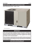
B5SM -090/120 SERIES Installation Instructions LIGHT COMMERCIAL AIR HANDLER Vertical Application Horizontal Application - Rear View Horizontal Application - Front View IMPORTANT Please read this information thoroughly and become familiar with the capabilities and use of your appliance before attempting to operate or maintain this unit. Keep this literature where you have easy access to it in the future. If a problem occurs, check the instructions and follow recommendations given. If these suggestions don’t eliminate your problem, call your servicing contractor. These instructions are primarily intended to assist qualified individuals experienced in the proper installation of this appliance. Some local codes require licensed installation/ service personnel for this type of equipment. Please read all instructions carefully before starting the installation. DO NOT DESTROY. PLEASE READ CAREFULLY AND KEEP IN A SAFE PLACE FOR FUTURE REFERENCE. Important Safety Information ....................................3 General Information ...................................................4 Before You Install this Unit .........................................4 Locating the Air Handler ............................................4 Field Connections for Electrical Power Supply ..........4 Air Ducts ....................................................................4 Unconditioned Spaces ...........................................4 Acoustical Duct Work .............................................4 Air Handler Installation ..............................................5 Packaging Removal ...................................................5 Minimum Clearance Requirements ...........................5 Horizontal Mounting Applications ..............................5 Vertical Mounting Applications ..................................5 Condensate Drain ....................................................5 Connecting Refrigerant Tubing ..................................5 Filter Requirements ..................................................6 Electrical Wiring..........................................................7 Pre - Electrical Checklist ...........................................7 Line Voltage ...............................................................7 Thermostat Connections ...........................................7 Electrical Wiring with a Duct Heater ..........................7 Unbalanced 3-Phase Supply Voltage ........................8 Grounding..................................................................8 Startup & Adjustments ..............................................8 Pre - Start Checklist ..................................................8 Motor Sheave Adjustment .........................................8 Pulley Alignment........................................................9 Belt Tensioning ..........................................................9 Blower Adjustments...................................................9 Unit Maintenance ........................................................9 Figures & Tables ....................................................... 10 Figure 4. Physical Dimensions - Horizontal.......... 10 Figure 5. Physical Dimensions - Vertical .............. 11 Table 4. Blower Performance Data ....................... 12 Electrical Information ............................................... 13 Figure 6. B5SM Wiring Diagram ........................... 13 Figure 7. Air conditioner T-stat Connections......... 14 Figure 8. Heat pump T-stat Connections .............. 15 Figure 9. Maintenance Schedule ......................... 16 2 IMPORTANT SAFETY INFORMATION Safety markings are used frequently throughout this manual to designate a degree or level of seriousness and should not be ignored. WARNING indicates a potentially hazardous situation that if not avoided, could result in personal injury or death. CAUTION indicates a potentially hazardous situation that if not avoided, may result in minor or moderate injury or property damage. WARNING: NITROGEN HEALTH 1 FLAMMABILITY 0 REACTIVITY 0 0 Minimal Hazard 1 Slight Hazard Evaporator coils are shipped from the factory with a nitrogen charge. Use caution when preparing coils for field connections. If repairs make it necessary for evacuation and charging, it should only be attempted by qualified, trained personnel thoroughly familiar with this equipment. Some local codes require licensed installation service personnel to service this type of equipment. Under no circumstances should the equipment owner attempt to install and/or service this equipment. Failure to comply with this warning could result in equipment damage, personal injury, or death.. WARNING: Improper installation, service, adjustment, or maintenance may cause explosion, fire, electrical shock or other hazardous conditions which may result in personal injury or property damage. Unless otherwise noted in these instructions, only factory authorized kits or accessories may be used with this product. WARNING: WARNING: The safety information listed below must be followed during the installation, service, and operation of this unit. Unqualified individuals should not attempt to interpret these instructions or install this equipment. Failure to follow safety recommendations could result in possible damage to the equipment, serious personal injury or death. • The installer must comply with all local codes and regulations which govern the installation of this type of equipment. Local codes and regulations take precedence over any recommendations contained in these instructions. Consult local building codes and the National Electrical Code (ANSI CI) for special installation requirements. • This equipment contains liquid and gaseous refrigerant under high pressure. Installation or servicing should only be performed by qualified trained personnel thoroughly familiar with this type equipment. • All electrical wiring must be completed in accordance with local, state and national codes and regulations and with the National Electric Code (ANSI/NFPA 70) or in Canada the Canadian Electric Code Part 1 CSA C.22.1. • Installation of equipment may require brazing operations. Installer must comply with safety codes and wear appropriate safety equipment (safety glasses, work gloves, fire extinguisher, etc.) when performing brazing operations. • Install this unit only in a location and position as specified on pages 4 & 5. This unit is designed only for Indoor installations and should be located with consideration of minimizing the length of the supply and return ducts. See Table 4 (page 12) and the rating plate for proper circulating airflow data • Consideration should also be given to the accessibility of fuel, electric power, service access, noise, and shade. Physical dimensions for each type of installation is shown on pages 10 & 11. See Figure 4 for horizontal installations or Figure 5 for Vertical installations. • Follow all precautions in the literature, on tags, and on labels provided with the equipment. Read and thoroughly understand the instructions provided with the equipment prior to performing the installation and operational checkout of the equipment. Unless otherwise noted in these instructions, only factory authorized kits or accessories may be used with or when modifying this product. 3 GENERAL INFORMATION B5SM air handlers are shipped from the factory ready for installation in a horizontal position. The units can be easily reconfigured in the field for vertical applications. The return air opening is interchangeable between the bottom of the unit and the top panel simply by switching the filter-rack with the return air cover panel. For either configuration, sufficient clearance must be provided on the sides of the unit to allow access for servicing the blower, motor, coil assembly, and filters. This unit has been designed and tested for capacity and efficiency in accordance with A.R.I. Standards. This unit will provide many years of safe and dependable comfort, providing it is properly installed and maintained. With regular maintenance, this unit will operate reliably year after year. Abuse, improper use, and/ or improper maintenance can shorten the life of the appliance and create unsafe hazards. Before You Install the Air Handler This equipment is securely packed at the time of shipment and upon arrival should be carefully inspected for damage prior to installing the equipment at the job site. Claims for damage (apparent or concealed) should be filed immediately with the carrier. The cooling load of the area to be conditioned must be calculated and a system of the proper capacity selected. Check the electrical supply and verify the power supply is adequate for unit operation. The system must be wired and provided with circuit protection in accordance with local building codes. If there is any question concerning the power supply, contact the local power company. The air handler should be installed before routing the refrigerant tubing. Refer to the indoor unit’s installation instructions for installation details. Verify the air delivery of the/air handler is adequate to handle the static pressure drop of the coil, filter, and duct work. Please consult your dealer for maintenance information and availability of maintenance contracts. Please read all instructions before installing the unit. Locating the Air Handler • Survey the job site to determine the best location for mounting the unit. • Overhead obstructions, poorly ventilated areas, and areas subject to accumulation of debris should be avoided. • Consideration should be given to availability of electric power, service access, noise, and shade. Field Connections for Electrical Power Supply • All wiring must comply with current provisions of the National Electrical Code (ANSI/NFPA 70) and with applicable local codes having jurisdiction. • The minimum size of electrical conductors and circuit protection must be in compliance with information listed on the outdoor unit data label. • Electrical power supplied to the unit must be adequate for proper operation of the equipment. The system must be wired and provided with circuit protection in accordance with local building codes. 4 Air Ducts This unit is designed only for use with a supply and return duct. Air ducts should be installed in accordance with the standards of the National Fire Protection Association Standard for Installation of Air Conditioning Systems (NFPA 90A), Standard for Installation of Residence Type Warm Air Heating and Air Conditioning Systems (NFPA 90B), and all applicable local codes. NFPA publications are avaialable by writing to: National Fire Protection Association, Batterymarch Park, Quincy, ME 02269 or visit www.NFPA.org on the web. • Design the duct work according to methods described by the Air Conditioning Contractors of America (ACCA). • The return air duct must have the same free area as the opening provided on the blower coil unit. • Duct work should be attached directly to the unit flanges for horizontal and vertical applications. See Figures 4 or 5 (pages 10 or 11). Unconditioned Spaces All duct work passing through unconditioned space must be properly insulated to minimize duct losses and prevent condensation. Use insulation with an outer vapor barrier. Refer to local codes for insulation material requirements. Acoustical Duct Work Certain installations may require the use of acoustical lining inside the supply duct work. • Acoustical insulation must be in accordance with the current revision of the Sheet Metal and Air Conditioning Contractors National Association (SMACNA) application standard for duct liners. • Duct lining must be UL classified batts or blankets with a fire hazard classification of FHC-25/50 or less. • Fiber duct work may be used in place of internal duct liners if the fiber duct work is in accordance with the current revision of the SMACNA construction standard on fibrous glass ducts. Fibrous duct work and internal acoustical lining must be NFPA Class 1 air ducts when tested per UL Standard 181 for Class 1 ducts. AIR HANDLER INSTALLATION Packaging Removal Remove the shipping crate and User’s Manual from the equipment.Take care not to damage the tubing connections when removing the crate. Minimum Clearance Requirements This air handler must be installed with ample clearance for easy access to the air filters, blower assembly, and, controls. Allow 24 inches minimum clearance from the front of the motor and refrigerant access panels for service and maintenance. However 36 inches is strongly recommended. Horizontal Mounting Applications B5SM air handlers can be suspended from support rods at each corner and are supplied with the required 1/2-13 NC hardware. The installer only needs to supply the ½” full threaded support rods in an appropriate length for their application. NOTE: These units can be supported with 3/8” full threaded support rods, however all mounting hardware must be field supplied. Once in position, verify the unit is level. See Figure 4 (page 10). CAUTION: When raising the air-handler for horizontal mounting, always use safe lifting methods and equipment. Always support the unit along its entire width. Failure to do so may result in damage to the lower panels or other equipment. If determined safe for your application the shipping pallet may be utilized with a forklift for this operation. Vertical Mounting Applications Verify the unit is level and there is adequate clearances to service the unit and provide the minimum 2” trap needed for the condensate drain. See Figure 5 (page 11). Condensate Drain B5SM air handlers have condensate drain ports on both sides of the unit, and may be configured for drainage from the left, right or both sides (Figures 4 or 5). Connection to the drains can be made with a ¾” threaded PVC adapter. Units are configured at the factory with the service side drain open and a threaded PVC drain plug installed on the opposite side. Each drain line installed requires its own drain trap. To ensure proper drainage, the installed drain trap(s) must provide a minimum trap of 2 inches. Note: It is recommended that a secondary drain pan be used when the unit is hung above an enclosed ceiling. Connecting Refrigerant Tubing WARNING: NITROGEN HEALTH 1 FLAMMABILITY 0 REACTIVITY 0 0 Minimal Hazard 1 Slight Hazard Evaporator Coils are factory shipped with a nitrogen charge. Avoid direct face exposure or contact with valve when gas is escaping. Always ensure adequate ventilation is present during the depressurization process. Any uncertainties should be addressed before proceeding. • When connecting refrigerant linesets together, it is recommended that dry nitrogen be flowing through the joints during brazing. This will prevent internal oxidation and scaling from occurring. • Refrigerant tubing should be routed in a manner that minimizes the length of tubing and the number of bends in the tubing. • Refrigerant tubing should be supported in a manner that the tubing will not vibrate or abrade during system operation. • Tubing should be kept clean of foreign debris during installation. • Every effort should be made by the installer to ensure that the field installed refrigerant containing components of the system have been installed in accordance with these instructions and sound installation practices to insure reliable system operation and longevity. • Always refer to the installation instructions supplied with the outdoor unit for piping requirements. The suction and liquid lines must be sized in accordance with the condensing unit specifications. • If precise forming of refrigerant lines is required, a copper tubing bender is recommended. Avoid sharp bends and contact of the refrigerant lines with metal surfaces. • A filter dryer is provided with the unit and must be installed in the liquid line of the system. If the installation replaces a system with a filter dryer already present in the liquid line, the filter dryer must be replaced with the one supplied with the unit. The filter dryer must be installed in strict accordance with the manufacturer’s installation instructions. • B5SM air handlers are supplied with a direct expansion refrigerant coil and thermostatic expansion valves. Refrigerant line connections are located on the motor side (service side) of cabinet and require sweat connections. 5 • The B5SM-120 air handler has a dual circuit coil and the B5SM-090 has a single circuit coil. • The B5SM-120 air handler is charged through service valves on the end of the liquid tube for each circuit. These must be removed before brazing the line sets. The B5SM-090 is charged through a service valve inside the unit, which should not be removed. • Before brazing the B5SM-090, remove the core from the service port. Failure to do this may result in a leak at the service valve. Replace the core and cap once brazing is complete. • Optional equipment such as liquid line solenoid valves, low ambient, etc., should be installed in strict accordance with the manufacturer’s installation instructions. Filter Requirements B5SM air handlers are shipped with three permanent 1” filters; however the filter rack can be converted to accommodate a 2” filter. To convert to a 2” filter: 1. Remove all filters from the unit. 2. Locate and remove the 4 screws (Figure 1) holding the bottom filter slide assembly (latch end) to the filter rack frame. NOTE: Be careful when removing the slide assembly so it does not drop into unit and cause damage to the coil. 3. Remove the 4 screws securing the “L” bracket to the “Z” bracket. 4. Rotate the “L” bracket 180 degrees, and reposition it so it mounts flush with the “Z” bracket. See Figure 1. 5. Secure the filter slide assembly together with the four screws. 6. Re-install the filter slide assembly back into the filter rack frame and secure with the 4 screws removed earlier. If replacing factory supplied filters with disposable filters, use only 2” disposable filters. Accessing the filters does not require tools and can be performed from either side of the filter-rack. On the service side of the unit, locate the release knob at the base of the filter rack and rotate clockwise to unlock, then pull up and out to remove the filter access panel. On the blower side, use the same method but rotate counter-clockwise to unlock. Model B5SM Filter Resistance Size (W.C.) 0.03 0.04 0.05 18 x 24 (1”) 0.07 0.08 0.09 0.05 0.07 0.08 18 x 24 (1”) 0.09 0.11 0.13 Nominal CFM 2200 2600 3000 3400 3800 4200 3000 3400 3800 4200 4600 5000 090 120 Table 1. Pressure Drop Across Filters FILTER BRACKET LOCATION BRACKET CONFIGURATION FOR 2” FILTER APPLICATIONS BRACKET CONFIGURATION FOR 1” FILTER APPLICATIONS (FACTORY SETTING) FILTERS “Z” BRACKET “L” BRACKET REMOVE 4 SCREWS FROM FILTER RACK FRAME REMOVE 4 SCREWS SECURING “Z” BRACKET AND “L” BRACKET Figure 1. Converting from 1” Filter to 2” Filter Applications MODEL VOLTAGE PHASE Hz FLA HP MCA MOP -090 & -120 J 208-230/460 3 60 6.6-6.6/3.3 2 8.3-8.3/4.2 15 -090 & -120 K 208-230 1 60 11.3-10.0 2 14.2-12.5 25-20 FLA = Full Load Amps, MCA = Minimum Circuit Ampacity, MOP = Maximum Over-Current Protection Table 2. Electrical Rating Data 6 ELECTRICAL WIRING WARNING: To avoid risk of electrical shock, personal injury, or death, disconnect all electrical power to the unit before performing any maintenance or service. The unit may have more than one electrical supply. Label all wires prior to disconnection when servicing the unit. Wiring errors can cause improper and dangerous operation. • Electrical connections must be in compliance with all applicable local codes and ordinances, and with the current revision of the National Electric Code (ANSI/NFPA 70). • For Canadian installations, the electrical connections and grounding shall comply with the current Canadian Electrical Code (CSA C22.1 and/or local codes). Pre-Electrical Checklist: Verify that the voltage, frequency, and phase of the supply source match the specifications on the unit rating plate. The label is located near the refrigerant lines. Verify that the service provided by the utility is sufficient to handle the additional load imposed by this equipment. Phase balance on 3 phase units must always be checked. See Unbalanced 3-Phase Supply Voltage (page 8). Line Voltage • It is recommended that the line voltage to the unit be supplied from a dedicated branch circuit containing the correct fuse or circuit breaker for the unit. • An electrical disconnect must be located within sight of and readily accessible to the unit. This switch shall be capable of electrically de-energizing the outdoor unit. See unit data label for proper incoming field wiring. Any other wiring methods must be acceptable to authority having jurisdiction. • Refer to the unit wiring label for proper high and low voltage wiring. • Use only copper wire for the line voltage power supply to this unit (Table 2, page 6). Use proper code agency listed conduit and a conduit connector for connecting the supply wires to the unit. • Overcurrent protection must be provided at the branch circuit distribution panel and sized as shown on the unit rating label and according to applicable local codes. See the unit rating plate for maximum circuit ampacity and maximum overcurrent protection limits. • If replacing any of the original wires supplied with the unit, the replacement wire must be copper wire consisting of the same gauge and temperature rating. • Provide power supply for the unit in accordance with the unit wiring diagram, and the unit rating plate. The installer should become familiar with the wiring diagram/ schematic before making any electrical connections to the unit. See Figure 6 (page 13). • These air handlers can be purchased in both single and three phase power configurations, all single phase equipment is shipped from the factory ready for field connections. For electrical connection locations see Figures 4 or 5 (pages 10 or 11). • Three phase units are shipped from the factory preconfigured for high voltage operation. The 460 volt, 60 hertz units may be reconfigured in the field for the other voltages indicated on the unit rating label . For additional Maximum Current Ampacity (MCA), or Maximum Overcurrent Protection (MOP) information, refer to the unit rating label. For proper high voltage wiring or other wiring requirements refer to the Wiring Diagram (Figure 6). • Internally mounted circuit breakers are available as field installed options. These circuit breakers can be used as an electrical disconnect. Thermostat Connections • Thermostat connections shall be in accordance with the instructions supplied with the thermostat and the indoor equipment. The low voltage wires must be properly connected to the units low voltage terminal block. • A single stage thermostat is used with this equipment and must operate in conjunction with any installed accessories. A typical AC and air handler hookup is shown in Figure 7 (page 14). For heat pump and air handler connections, see Figure 8 (page 15). • The thermostat should be mounted about 5 feet above the floor on an inside wall. DO NOT install the thermostat on an outside wall or any other location where its operation may be adversely affected by radiant heat from fireplaces, sunlight, or lighting fixtures, and convective heat from warm air registers or electrical appliances. Refer to the thermostat manufacturer’s instruction sheet for detailed mounting and installation information. Electrical Wiring with a Duct Heater Slip-in duct heaters are available as an accessory with the B5SM air handler. See Table 3 for available sizes. These heaters mount in the supply duct external to the air handler. The heater kits are available in 10, 16, 26, and 36 KW sizes and 240 or 460 voltages. All heater kits are set up for three phase operation. To wire the heater kits to the B5SM air handler unit, refer to the Installation Instructions supplied witht he kit. SKU 559428 559429 559430 559431 559432 559433 559434 559435 Kw 10 10 16 16 26 26 36 36 Volts/Phase/Hz 208-240/3/60 480/3/60 208-240/3/60 480/3/60 208-240/3/60 480/3/60 208-240/3/60 480/3/60 MODEL H7HK010Q-01 H7HK010S-01 H7HK016Q-01 H7HK016S-01 H7HK026Q-01 H7HK026S-01 H7HK036Q-01 H7HK036S-01 Table 3. Duct Mount Heater Kit Models 7 Unbalanced 3-Phase Supply Voltage Voltage unbalance occurs when the voltages of all phases of a 3-phase power supply are no longer equal. This unbalance reduces motor efficiency and performance. Some underlying causes of voltage unbalance may include: Lack of symmetry in transmission lines, large single-phase loads, and unbalanced or overloaded transformers. A motor should never be operated when a phase imbalance in supply is greater than 2%. Perform the following steps to determine the percentage of voltage imbalance: 1. M e a s u r e t h e l i n e voltages of your 3-phase power supply where it enters the building and at a location that will only be dedicated to the unit installation. (at the units circuit protection or disconnect). Example: AB = 451V BC = 460V AC = 453V 2. Determine the average voltage in the power supply. In this example, the measured line voltages were 451, 460, and 453. The average would be 454 volts (451 + 460 + 453 = 1,364 / 3 = 454). 3. Determine the maximum deviation: Example: From the values given in step 1, the BC voltage (460V) is the greatest difference in value from the average: Highest Value 460 - 454 = 6 454 - 451 = 3 454 - 453 = 1 4. Determine percent of voltage imbalance by using the results from steps 2 & 3 in the following equation. % Voltage Imbalance = 100 x Example: 100 x 6 = 1.32% 454 max voltage deviation from average voltage average voltage The amount of phase imbalance (1.32%) is satisfactory since the amount is lower than the maximum allowable 2%. Please contact your local electric utility company if your voltage imbalance is more than 2%. 8 Grounding WARNING: The unit cabinet must have an uninterrupted or unbroken electrical ground to minimize personal injury if an electrical fault should occur. Do not use gas piping as an electrical ground! This unit must be electrically grounded in accordance with local codes or, in the absence of local codes, with the National Electrical Code (ANSI/NFPA 70) or the CSA C22.1 Electrical Code. Use the grounding lug provided in the control box for grounding the unit. STARTUP AND ADJUSTMENTS Pre-Start Check List Prior to start-up, complete the following inspection: Verify the unit is level and condensate can drain. Check condensate drain line(s) for proper slope and trap. Verify the air handler is mounted securely. Verify the surrounding area and top of the unit is free from obstructions and debris. Check all ductwork connections. Make sure the duct work is adequetly sealed to prevent air leakage. Check all coil connections for leaks. Verify that the line voltage power leads are securely connected and the unit is properly grounded. Verify that the low voltage wires are securely connected to the correct leads on the low voltage terminal strip. Make sure the thermostat is wired correctly. Verify the blower rotates properly. Check the blower belt between the pulleys for proper tension and alignment. Verify the power supply branch circuit overcurrent protection is sized properly. Verify all filters are in place and all equipment access/ control panels are in place Motor Sheave Adjustment The motor sheave consists of an outer, moveable pulley face and an inner stationary face. To adjust the motor sheave, 1. Relieve the belt pressure by loosening motor mount bolts and the belt tensioning bolts on the motor mount. 2. Move the blower fan belt out of the way (if necessary) and loosen the set screw in the outer sheave face. 3. Rotate the face in increments of one half or full turns only. NOTE: This maintains the set screw position precisely over the flats on the pulley hub. Rotating the sheave clockwise (when viewed from the lead end of motor - opposit end of shaft) will make the blower run slower which decreases airflow. Rotating the sheave counter clockwise (as viewed from lead end) will cause the blower to speed up. 4. Tighten the setscrews after the desired adjustment has been made and verify the moveable face is properly secured. Pulley Alignment Inspect the pulley alignment between the motor sheave and blower pulley. If a misalignment occurs, adjust the location of the motor sheave by loosening the set-screw in the stationary face of the motor sheave. Relocate the sheave assembly on the motor shaft to ensure the belt will be straight and aligned (Figure 2). Tighten the set-screw and then reinstall the fan belt. Tighten the tensioning bolts as described below. Belt Tensioning Proper belt tension can be determined by testing the belt deflection at the midpoint of the pulleys. The belt should deflect ¼” per foot of span between the centers of the pulleys (Figure 3). After the proper tension has been applied, tighten the motor mount bolts to secure the assembly, and visually inspect the area to ensure all tools have been removed. Inspect all wire harness and routings in the vicinity and make sure there is adequate clearance for the wire harness. Blower Adjustments - 3 phase units only If blower is turning opposite of arrow direction, disconnect all power to unit and allow all rotating equipment to stop, then interchange any two field wired leads at the terminal block OR disconnect connections. The blower speed has been preset at the factory. For optimum system performance and comfort, it may be necessary to change the factory set speed. Adjustment of the blower speed is made through varying the pitch of the motor pulley, this adjustment allows for a wide range of installation applications. Refer to Table 4 (page 12) for blower performance data. WARNING: Never perform maintenance on energized or rotating equipment. Always disconnect electrical power and allow all rotating equipment to stop before servicing the unit. Failure to do so may result in personal injury, loss of limb, or death from electrical shock or entanglement in moving parts. UNIT MAINTENANCE The maintenance information listed below should be performed in accordance with the Maintenance Schedule shown in Figure 9 (page 16). Filters To clean permanent filters, remove the filters and wash gently with mild soap and water. Rinse in clean, hot water and allow to drain & dry thoroughly before reinstalling. Drain Pan The drain pan and the drain lines should be cleaned to allow condensate to drain properly. Remove any accumulation of residue or sludge from the drain pan. Inspect in and around the drain pan for rust, holes, and leaks. V-Belts Inspect for cracks, tears, and excessive or abnormal wear. V-belts tend to elongate over time with normal application and use. Ensure the belt always maintains adequate tension without over tightening. Belts which have been over tightened will wear out rapidly and may cause motor and blower bearings to receive undue strain and wear. As a result the unit could experience excessive vibration and noise problems. Figure 2. Proper Belt Alignment Blower Bearings The blower assembly incorporates sealed bearings. Under normal operating conditions, no maintenance is necessary for the life of the equipment. Blower Fan Wheel Inspect the blower wheel blades for accumulations of dirt and clean if necessary. Inspect mounting nut for tightness when done. 1/4 inch ot 1 fo Blower Motor and Assembly Inspect the blower assembly and motor mounting brackets for tightness and corrosion. Correct deficiencies if neccessary. The blower motor contains sealed bearings and under normal operating conditions, no maintenance is necessary for the life of the equipment. Figure 3. Proper Belt Tension 9 FIGURES & TABLES 3/4" Field Installed Hanging Rods 47 5/8" Center to Center 1 1/4" 2 7/32" 23 13/16" CL of Unit 1" CL of Gravity Electrical Connections Electrical Connections Air Flow Air Flow 13 5/8" 15 9/16" 6 3/4" 4 3/4" 15 11/16" 8 3/16" 5 11/16" 4 3/8" 17 11/16" 7 1/2 Ton Unit Refrigerant Line Connections 4 3/16" 17 13/16" (Top View Shown with Doors Removed) 10 Ton Unit Refrigerant Line Connections (Top View Shown with Doors Removed) Field Installed Hanging Rods 57" Center to Center 28 1/2" CL of Unit 3" CL of Gravity Front View Electrical Knock-outs 16 1/4" Condensate Drain 22 1/16" 18 13/16" Supply Duct 19 3/8" 60 1/4" Cabinet Width 1 5/8" 2 3/16" 25 1/16" Filter Rack 23" Return Duct Opening 57" Filter Rack Frame 1 5/8" 53" Return Duct Opening 27 3/8" Cabinet Height 2 3/16" Figure 4. B5SM Physical Dimensions for Horizontal Installations 10 Rear View 18 13/16" Supply Duct 19 3/8" 22 1/16" 16 1/4" Electrical Knock-outs Top View 27 3/8" Cabinet Depth (without Filter Rack) 60 1/4" Cabinet Width 19 3/8" 18 13/16" Supply Duct Opening 16 1/4" Supply Duct Opening 22 1/16" 9 1/8" 2 Electrical Connections 53 1/4" Cabinet Height 25 1/16" Filter Rack Frame 23" Return Duct Opening Condensate Drain 5 1/16" 53" Return Duct Opening 57" Filter Rack Frame Front View 29 5/16" Depth (with Filter Rack) Side View Figure 5. B5SM Physical Dimensions for Vertical Installations 11 12 Table 4. Blower Performance Data 0.5 0.6 0.7 External Static Pressures (Inches Water Column) 0.8 0.9 1.0 4707 822 1.92 4547 824 1.85 4416 826 1.77 4223 827 1.68 3996 829 1.60 3816 693 1.51 3565 625 1.20 3330 837 1.28 3051 839 1.19 1 Turn Open 4 Turns 2873 522 0.53 2785 534 0.54 Open 3 Turns 3896 708 1.17 3776 724 1.20 3587 731 1.16 3408 736 1.10 3151 740 1.02 2899 743 0.94 Open 2 Turns 4410 779 1.63 4258 780 1.56 4071 784 1.50 3867 786 1.45 3632 787 1.31 3396 790 1.23 3092 792 1.13 2826 794 1.01 Open * 4789 868 2.12 4640 868 2.00 4442 870 1.95 4208 873 1.87 4025 876 1.77 3875 877 1.68 3497 879 1.59 3207 882 1.49 Fully Closed * Denotes Factory Adjustable Sheave Setting Bold Indicates Factory Recommended Blower Operating Range Shaded Area -Not Recommended for Operation Values based on dry coils and do not include filter losses B5SM120 (2HP) 60 Hz 0.3 CFM RPM Kw CFM RPM Kw CFM RPM Kw CFM RPM Kw CFM RPM Kw CFM RPM Kw CFM RPM Kw CFM RPM Kw CFM RPM Kw 0.2 0.4 3283 554 0.79 2966 555 0.72 2619 555 0.65 2203 555 0.57 3268 592 0.82 3074 593 0.80 2783 593 0.74 2490 594 0.68 2052 597 0.59 3867 629 1.09 3638 630 1.01 3366 631 0.95 3055 632 0.85 2672 633 0.77 4182 666 1.28 3961 667 1.20 3706 668 1.11 3436 669 1.03 3081 669 0.93 2738 672 0.83 4 Turns 2611 486 0.57 2355 487 0.53 Open Fully Closed 1 Turn Open 2 Turns Open * 3 Turns Open External Static Pressures (Inches Water Column) Motor Sheave 0.2 0.3 0.4 0.5 0.6 0.7 0.8 0.9 1.0 Position CFM RPM Kw CFM RPM Kw CFM RPM Kw CFM RPM Kw CFM RPM Kw CFM RPM Kw CFM RPM Kw CFM RPM Kw CFM RPM Kw Motor Model Sheave Position B5SM090 (2HP) 60 Hz Model AIRFLOW DATA T2 L2 T1 L1 BLACK GREEN BLACK SEE NOTE 3 L1 L2 G FIELD SUPPLY CONNECTIONS FIELD WIRING LOW VOLTAGE LEGEND: G L1 L2 BROWN FREEZESTAT R Y T3 GREEN G W2 W1 R Y L2 L3 L1 L2 L3 G FIELD SUPPLY CONNECTIONS L1 BLACK C T2 BLACK SEE NOTE 3 C T1 BROWN Y Tstat O/B G L1 L2 L3 FREEZESTAT THREE PHASE O/B G W2 W1 Y Tstat 208-230/460V 0 46 0 23 SINGLE PHASE 3. Three phase, 60 Hz units may be configured for 208-230V operation by relocating the internal selector pin at the rear of the motor as shown below. (See product literature for more information, if necessary.) 820 THREE PHASE ONLY NOTES: 1. Three phase units are factory wired for 460V/60Hz or 380V/50Hz operation. 2. To reverse motor rotation, interchange any two field wired line leads. Three Phase 208-230/460V 380V 1009 7109700 0 46 0 23 GENERAL NOTES: 1. Disconnect all power before servicing. 2. If wiring must be replaced, use only 105˚C copper wire of the same gauge. 3. For economizer application, remove black wire from low voltage board “Y” terminal and connect to yellow wire from economizer. Single Phase 208-230V 220V 8- Frequency 60 Hz 50 Hz Electrical Configurations 20 B5SM Series 7.5/10T Air Handler Systems ELECTRICAL INFORMATION Figure 6. Wiring for Single and Three Phase Units 13 NOTE: C &W2 to be connected to electric heat. TO FIELD SUPPLIED DISCONNECT GND SINGLE STAGE HEAT/COOL THERMOSTAT L1 R W C G Y L2 OPTIONAL L3 BLOWER MOTOR FREEZESTAT GREEN BROWN G C W2 W1 O Y R C Y R BLACK See Note BLACK TERMINAL BOARD AIR HANDLER SECTION OUTDOOR SECTION SINGLE STAGE HEAT/COOL THERMOSTAT- NO ECONOMIZER NOTES: TO FIELD SUPPLIED DISCONNECT GND SINGLE STAGE HEAT/COOL THERMOSTAT L1 R W C G Y L2 OPTIONAL L3 C Y R FREEZESTAT B Y1 BLACK G C W2 W1 O Y R GRY W7459A GRY-90” A 7 B 9 GRN-18” GRN-18” VIO-14” 4 1 GRN 6 3 s BLU-14” C7400A TR1 So JUMPER WIRE Sr 5 YEL-18” Note 3 Y2 WHITE ORN BLUE 2 3 4 RED-12” T T1 P P1 RED C7150 M.A.S. 1S 2K 1S RED AIR HANDLER SECTION 1 OPTIONAL ECONOMIZER SECTION SINGLE STAGE HEAT/COOL THERMOSTAT- WITH ECONOMIZER Figure 7. Typical Air conditioner Thermostat Connections 14 M7415A TR BLK Note 1 TB-11 TR 1 TR BLK-12” YEL Note 2 GREEN TERMINAL BOARD OUTDOOR BLOWER MOTER Note 4 BLACK 1. C & W2 to be connected to electric heat. 2. Remove BLACK wire from air handler low voltage terminal board Y terminal and connect to YELLOW wire from economizer. 3. 2nd Stage refrigerant cooling with optional economizer installed. A 2 stage thermostat is required for simultaneous operation of the economizer and refrigerant system. Connect Y2 from 2 stage thermostat to BLUE wire from economizer. If installing an economizer in this unit, refer to the Economizer installation instructions for proper set up and operation. 4. Heat Pump Economizer Relay. For heat pump applications only, connect B from thermostat to GREY wire from Economizer. Required for proper operation of an economizer (optional) in the heat pump Heating mode. If installing an economizer in this unit, refer to the Economizer installation instructions for proper set up and operation. GRY-12” BLK-12” BLU-12” T T1MA P1 MIN. P POT. NOTES: 1. Jumper between W2 and E is required. 2. C &W2 to be connected to electric heat. TO FIELD SUPPLIED DISCONNECT GND SINGLE STAGE HEAT PUMP THERMOSTAT L1 R O W2 E C G Y B L2 L3 NOTE 1 BLOWER MOTER FREEZESTAT BROWN G C C W2 O R Y GREEN BLACK W2 O R Y W1 NOTE 2 BLACK TERMINAL BOARD OUTDOOR SECTION AIR HANDLER SECTION TYPICAL HEAT PUMP THERMOSTAT CONNECTION (NO ECONOMIZER) NOTES: 1. Jumper between W2 and E is required. TO FIELD SUPPLIED DISCONNECT GND SINGLE STAGE HEAT PUMP THERMOSTAT L1 R O W2 E C G Y B L2 L3 NOTE 1 BLOWER MOTER NOTE 5 FREEZESTAT Y1 GREEN BLACK B 9 GRN-18” GRN-18” TB-11 M7415A TR TR TR 1 BLK-12” VIO-14” 4 1 6 3 s BLU-14” C7400A TR1 So JUMPER WIRE Sr BLACK 5 YEL-18” NOTE 2 NOTE 4 Y2 1 2 WHITE ORANGE BLUE C7150 M.A.S. RED-12” 1S T T1 P P1 RED AIR HANDLER SECTION 1S 2K 3 4 RED TERMINAL BOARD OUTDOOR SECTION W7459A GRY-90” A 7 YELLOW NOTE 3 GREEN G C W2 O R Y W1 GREY B BLACK BROWN C W2 O R Y 2. C & W2 to be connected to electric heat. 3. Remove BLACK wire from air handler low voltage terminal board Y terminal and connect to YELLOW wire from economizer. 4. 2nd Stage refrigerant cooling with optional economizer installed. A 2 stage thermostat is required for simultaneous operation of the economizer and refrigerant system. Connect Y2 from 2 stage thermostat to BLUE wire from economizer. If installing an economizer in this unit, refer to the Economizer installation instructions for proper set up and operation. 5. Heat Pump Economizer Relay. Connect B from thermostat to GREY wire from Economizer. Required for proper operation of an economizer (optional) in the heat pump Heating mode. If installing an economizer in this unit, refer to the Economizer installation instructions for proper set up and operation. OPTIONAL ECONOMIZER GRY-12” BLK-12” BLU-12” T T1MA P1 MIN. P POT. TYPICAL HEAT PUMP THERMOSTAT CONNECTION (WITH ECONOMIZER) Figure 8. Typical Heat Pump Thermostat Connections 15 Installed by: Date Installed: Maintenance Task Performance Schedule W Date Performed: M SA A Air Filters Inspect, clean or replace as required. x Condensate Drain(s) & Pan Clean condensate drain pan Inspect the flow of condensate through the drain lines. Clean or Correct problems as necessary. x x Blower Assembly Inspect the fan belt for wear, alignment & and proper tension. Replace or adjust as required. Clean the blower wheel and housing. x x x Inspect the blower assembly for corrosion and all hardware for security. Inspect the blower coil unit casing for corrosion and loose fasteners. x Coils Inspect the coil fins for excessive dirt or damage. Clean or repair if required. Inspect all coil connections for leaks. x x Air Handler Assm. Inspect Mounting Hardware for security and corrosion Inspect Filter Rack mounting hardware for security Inspect panel assemblies for proper installation and security x x x Figure 9. Maintenance Schedule NOTE: The schedule above is for normal duty applications only. For severe duty applications, adjust schedule as appropriate. Additional tasks may be required for severe duty applications. The installer performing this work assumes all responsibility for this installation. Safety should always be the deciding factor when installing this product and using common sense plays an important role as well. Improper installation of the components or failure to follow safety warnings could result in serious injury, death, or property damage. After completing the installation, return these instructions to the equipment owner’s package for future reference. ¢7090950K¤ O’Fallon MO 7090950 7090950 Specifications and illustrations subject to change without notice or incurring obligations. Printed in U.S.A. (01/10)