1
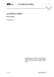
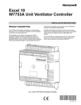
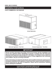
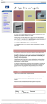
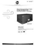
W7340, W7345
Communicating Economizer Logic Modules
FOR VENTILATION CONTROL
PRODUCT DATA
FEATURES
• Solid state control package provides accuracy,
reliability and stability.
• Housed in high-impact, glass-fiber reinforced plastic
case.
W7340
• Terminals included for connecting optional S963B1136
Remote Potentiometer for remote minimum damper
position control.
• Communicates using a modified Modbus protocol.
W7345
APPLICATION
The W7340 Communicating Economizer Logic Module is a full
featured economizer that incorporates Demand Control
Ventilation (DCV) to provide free cooling and ventilation for
occupants in a space while saving energy.
The W7345 Communicating Economizer Logic Module is a
dry bulb only economizer that does not incorporate Demand
Control Ventilation.
The W7340 is used with both solid state temperature and
humidity or enthalpy sensors. The W7345 is used with solid
state temperature sensors only.
• Case matches the lines of the M7215 Damper Motor.
• LED indicates the status of the device input.
W7340 Only
• Operates from the Modbus input, environmental
sensors, and a DCV sensor to provide a totally
integrated control system.
• Combines minimum damper position potentiometer
with solid state temperature (10K NTC) and humidity or
enthalpy changeover control to provide economizer
free cooling function; this control can be overridden
by input via Modbus or DCV sensor.
W7345 Only
• Operates from the Modbus input and mixed/discharge
air sensor to provide a temperature control system.
• Combines the Modbus indoor and/or outdoor
temperature input with the mixed air input to provide
economizer dry bulb free cooling function.
Contents
Application.........................................................................1
Features ............................................................................1
Specifications ....................................................................2
Installation .........................................................................3
Wiring ................................................................................6
Operation...........................................................................7
Settings and Adjustment ...................................................7
Troubleshooting.................................................................11
63-2569—04
W7340, W7345 COMMUNICATING ECONOMIZER LOGIC MODULES
SPECIFICATIONS
Models:
W7340: Communicating Economizer Logic Module with
minimum position potentiometer, setpoints for enthalpy or
dry-bulb, and DCV.
W7345: Communicating Economizer Logic Module with
minimum position potentiometer and setpoint for dry-bulb
temperature only.
IMPORTANT
W7340A, W7340B and W7345A:
1. Do not have the ability to set DCV minimum position
for damper position for demand control ventilation.
Damper may drive 100% open on call from CO2
sensor.
2. Do not have the E (enthalpy or dry bulb) curve
setting.
3. W7340C has the ability to set DCV minimum position
and has the E curve setting.
Approvals:
cUL listed.
Underwriters Laboratories Inc. listed:
Meets UL873 plenum requirements.
Meets UL94-5VA plenum flammability requirements.
FCC Part 15 Class B.
CE.
This product complies with Title 24 Part 6 CEC standard for
Residential and Non-Residential Buildings - 2005, when
installed according to instructions.
4-1/16
(103)
1-15/16
(49)
Dimensions: See Fig. 1.
1-3/4 (44)
4-7/16 (112)
Temperature Ratings:
Operating Ambient: -40 to +149 °F (-40 to +65 °C).
Shipping: -25 to +125 °F (-32 to +52 °C).
1-3/8
(35)
5/8
(16)
Humidity Ratings:
Noncondensing: 5 to 95% RH.
Condensing: 100% RH.
M22813
Fig. 1. Dimensions of W7340 and W7345 in inches (mm).
Inputs and Outputs: See Table 1.
Electrical Ratings:
Input Voltage: 24 Vac ±25%; 50/60 Hz (Class 2).
Nominal Power Consumption (at 24 Vac, 60 Hz): 5 VA.
Relay Contact Rating at 30 Vac (maximum power from class 2
input only): 1.5 A run, 7.5 A inrush.
Patents:
U.S. Patent 6,1,764.
Other Patents Pending.
Accessories:
32005191-001 Sensor, 10K ohm with 2-1/4 in. (57 mm) probe.
C7150B1046 Mixed Air Sensor, 10K ohm with mounting
bracket.
C7232 Carbon Dioxide Sensor for DCV.
C7632 Carbon Dioxide Sensor for DCV.
C7400A Solid State Enthalpy Sensor for use with W7340A
and W7340B.
C7400C Solid State Enthalpy Sensor for use with W7340C.
C7600C Relative Humidity Sensor.
S963B1136 Remote Potentiometer to provide remote control
of damper minimum position.
ST6008 Energy Management Timer for occupied/unoccupied
control.
ST7009 Electronic Programmable Timer for occupied/
unoccupied control.
ORDERING INFORMATION
When purchasing replacement and modernization products from your TRADELINE® wholesaler or distributor, refer to the
TRADELINE® Catalog or price sheets for complete ordering number.
If you have additional questions, need further information, or would like to comment on our products or services, please write or
phone:
1. Your local Honeywell Automation and Control Products Sales Office (check white pages of your phone directory).
2. Honeywell Customer Care
1885 Douglas Drive North
Minneapolis, Minnesota 55422-4386
In Canada—Honeywell Limited/Honeywell Limitée, 35 Dynamic Drive, Toronto, Ontario M1V 4Z9.
International Sales and Service Offices in all principal cities of the world. Manufacturing in Australia, Canada, Finland, France,
Germany, Japan, Mexico, Netherlands, Spain, Taiwan, United Kingdom, U.S.A.
63-2569—04
2
W7340, W7345 COMMUNICATING ECONOMIZER LOGIC MODULES
Location and Mounting
Table 1. Logic Module Inputs and Outputs.
W7340
W7345
Communicating Economizer Logic Modules
Inputs
Enthalpy
4-20
Modbus
yes
yes
Return Sensor
optional
—
Mixed/Discharge Air
10K ohma
10K ohma
Outdoor Sensor
10K ohma
—
Indoor DCV Sensor
0-10 Vdc control signal
—
mAa
—
Remote Minimum
optional
Position Potentiometer
optional
Motor Feedback
2-10 Vdc
—
Modbus
yes
yes
Exhaust
One set of 24 Vac
contacts (spst)
—
Motor Output Signal
2-10 Vdc
—
NOTE: Refer to Figures 4 and 5 for representative locations
of connected system devices.
CAUTION
Equipment Damage Hazard.
Mounting screws longer than 5/8 in. can damage
internal motor components.
When mounting the module to an M7215 use only the
included #6 5/8 in. thread-forming screw.
Outputs
a 2-wire
When planning the installation, allow enough clearance for
maintenance and service. Mount the device in a location
protected from rain, snow, and direct sunlight. The logic
module mounts on the side of an M7215 Damper Motor or
directly on a sheet metal duct or panel.
MOUNTING DIRECTLY TO THE MOTOR
1. Mount the motor.
2. Secure the W7340 or W7345 to the motor using the
supplied mounting screw (See Fig. 2).
(18, 20, 22 AWG) connection.
MOUNTING SEPARATE FROM THE MOTOR
Secure the device to the sheet metal using appropriate
fasteners (not supplied)(See Fig. 3).
INSTALLATION
When Installing this Product...
1.
2.
3.
4.
Read these instructions carefully. Failure to follow them
could damage the product or cause a hazardous
condition.
Check the ratings given in the instructions and on the
product to make sure the product is suitable for your
application.
Installer must be a trained, experienced service
technician.
After installation is complete, check out product
operation as provided in these instructions.
5/8 INCH SCREW INCLUDED
WITH LOGIC MODULE.
ECONOMIZER
LOGIC MODULE
IMPORTANT
All wiring must agree with applicable codes,
ordinances and regulations.
CAUTION
Electrical Shock or Equipment Damage Hazard.
Can shock individuals or short equipment
circuitry.
Disconnect power supply before installation.
M7215
DAMPER
MOTOR
M17550B
Fig. 2. Mounting Economizer Logic Module on Damper
Motor.
3
63-2569—04
W7340, W7345 COMMUNICATING ECONOMIZER LOGIC MODULES
IMPORTANT
• Ensure proper polarity of sensor connections.
Incorrect polarity negates the sensor signal.
W7340B: The W7340B DCV economizer logic modules
incorporate a minimum position setting that defaults to 20%,
but can be overridden using the Modbus communication link.
The W7340B DCV maximum position sets the damper position
to a position that the damper goes to if the CO2 sensor fails. If
the minimum position set point is higher than the DCV
maximum position, on sensor failure, the damper goes to the
higher of the two DCV maximum and minimum position setting.
There is no limit on the damper position on a call from the CO2
sensor (DCV); the damper can go 100% open.
W7340C: The W7340C DCV economizer logic module has the
ability to set DCV minimum damper position and minimum
position. The DCV minimum position is set to ventilate the
building contaminants and the minimum position is set to
ventilate for the building contaminants and the building
occupants. The installer sets the damper DCV minimum
position and the minimum position based on the design
occupancy and CFM of outdoor air requirements for the space.
The damper will modulate open between the DCV minimum
damper position and the minimum position based on input
from a CO2 sensor. The damper will not drive 100% open on a
call for ventilation, but can drive 100% open on a call for
cooling. If the CO2 sensor fails the damper will drive to the
minimum position ventilating for building contaminants and
the building occupants. If the DCV minimum position has not
been set using the following procedure, the default setting will
be 50% of the minimum position setting.
M17638
Fig. 3. Mounting to a Duct or Panel.
Enthalpy Sensor (W7340 only)
To measure enthalpy, the logic module accepts signals from
either:
— C7600C Humidity and 10K NTC temperature sensors.
— or a C7400 Enthalpy Sensor.
DCV Min and Min Position Damper Set Up
IMPORTANT
• When using C7400 Enthalpy Sensors, connect the
enthalpy sensors to the humidity sensor terminals;
leave the temperature sensor terminals empty.
• Use C7400A sensor with W7340A or W7340B.
• Use C7400C sensor with W7340C.
OUTDOOR AIR SENSING
1. Mount each sensor in any orientation that exposes it to
freely circulating air and protects it from rain, snow, and
direct sunlight.
2. Connect it to the logic module.
RETURN AIR SENSING
1. For differential enthalpy or temperature control mount a
second sensor in the return air duct.
2. Connect it to the logic module.
Demand Control Ventilation (DCV) Sensor Input
(W7340 only)
The DCV sensor can be any sensor that provides a 0-10 Vdc
output over a range of 0 to 2000 ppm of CO2. The DCV signal
modulates the outdoor damper to provide ventilation based on
occupancy. Mount the sensor according to the manufacturer
specifications. If not available, mount the sensor in an area
with unobstructed air circulation.
63-2569—04
4
Set up instructions for W7340C DCV damper positions:
1. Remove RAT sensor from RAT terminals.
2. Connect CO2 sensor to DCV terminals.
3. Apply power to economizer logic module.
4. Wait 10 to 15 seconds for the CO2 sensor to initialize.
Short RAT terminals.
5. Remove CO2 sensor from DCV terminals.
6. DCV LED will blink 2 times. If LED does not blink, cut
power to economizer logic and repeat steps 1-5.
7. Set DCV minimum position using MIN POS/DCV MIN
potentiometer.
8. Remove RAT short.
9. DCV minimum position is saved to memory and DCV
LED blinks 5 times.
10. Turn off power to economizer logic module.
11. Connect RAT sensor.
12. Turn power on to economizer logic module.
13. Set minimum position using MIN POS/DCV MIN
potentiometer.
IMPORTANT
Steps 3-8 must be completed within 3 minutes after
power up otherwise the configuration process will be
terminated, no changes will be saved and you will
need to repeat steps 1-13.
W7340, W7345 COMMUNICATING ECONOMIZER LOGIC MODULES
10K NTC
DISCHARGE
AIR SENSOR
MODBUS
C7232
2
DIRECT
EXPANSION
COIL
MIXED AIR
SENSOR
10K
NTC
2
INDOOR
FAN
C7400
INDOOR
AIR CO2
SENSOR
1
3
ENTHALPY
SENSOR
DISCHARGE
AIR
OUTDOOR
AIR
M7215 MOTOR
WITH W7340
ECONOMIZER
LOGIC MODULE
1
C7400
1
FOR DIFFERENTIAL ENTHALPY, THE TWO C7400 ENTHALPY SENSORS
ARE CONNECTED TO THE ECONOMIZER MODULE—ONE IS MOUNTED
IN THE RETURN AIR DUCT, AND THE OTHER IS MOUNTED IN THE
OUTDOOR AIR DUCT. DIFFERENTIAL ENTHALPY CONTROL PROVIDES
GREATER ENERGY SAVINGS THAN SINGLE ENTHALPY CONTROL.
3
ENTHALPY
SENSOR
EXHAUST
FAN
2
USE EITHER MIXED AIR SENSOR OR DISCHARGE AIR SENSOR, NOT BOTH.
3
A C7600 HUMIDITY SENSOR, USED IN CONJUNCTION WITH A 10K NTC
TEMPERATURE SENSOR CAN BE USED INSTEAD OF A C7400 ENTHALPY SENSOR.
FOR DRY BULB CONTROL, USE ONLY A 10K NTC TEMPERATURE SENSOR.
EXHAUST AIR
RETURN AIR
M22814
Fig. 4. Representative Locations of Connected W7340 Economizer System Devices.
10K NTC
DISCHARGE
AIR SENSOR
1
MODBUS
DIRECT
EXPANSION
COIL
10K
NTC
INDOOR
FAN
DISCHARGE
AIR
MIXED AIR
SENSOR
1
1
OUTDOOR
AIR
M7215 MOTOR
WITH W7345
ECONOMIZER
LOGIC MODULE
EXHAUST
FAN
EXHAUST AIR
1
USE EITHER MIXED AIR SENSOR OR DISCHARGE AIR SENSOR, NOT BOTH.
RETURN AIR
M22822
Fig. 5. Representative Locations of Connected W7345 Economizer System Devices.
5
63-2569—04
W7340, W7345 COMMUNICATING ECONOMIZER LOGIC MODULES
WIRING
IMPORTANT
1. All wiring must comply with applicable local codes,
ordinances and regulations.
2. Refer to Figures 6 and 7 for typical wiring diagrams.
3. All inputs and outputs to the device must be 24 Vac
Class 2.
4. Ensure proper polarity of sensor connections.
Incorrect polarity negates the sensor signal.
CAUTION
Electrical Shock or Equipment Damage Hazard.
Can shock individuals or short equipment
circuitry.
Disconnect power supply before installation.
NOTE: All connections with label designation ending in 1
(examples: TR1, P1) are ac/dc common connections.
MOD BUS –
MOD BUS +
2-10 Vdc
FEEDBACK
OUTPUT
2-10 Vdc
CONTROL
SIGNAL INPUT
M7215
24 VAC
TR1 TR
W7340
MOD
BUS
POWER
EXHAUST
CONTACTOR
MIXED
AIR TEMP
SENSOR
10K NTC
–
C7600C
OUTDOOR
AIR
HUMIDITY
3
3
–
RETURN
AIR TEMP
SENSOR
10K NTC
OUTDOOR
AIR TEMP
SENSOR
10K NTC
C7600C
RETURN
AIR
HUMIDITY
L1
+
L2
1
P
P1
TR
TR1
+
–
DCV
3
RAH
MAT
EXF
+
+
DCV
SETPOINT
E
OAH
A
–
RAT
MIN POS/
DCV MIN
+
–
2-10 Vdc
CONTROL
SIGNAL
OUTPUT
C
D
B
OAT
+
–
2-10 Vdc
FEEDBACK
INPUT
24 VAC
+
–
DCV
SENSOR
(0-10 Vdc)
S963B
CCW
OPEN
3
2
R
CW
CLOSE
B
W
1 PROVIDE DISCONNECT MEANS AND OVERLOAD PROTECTION AS REQUIRED.
2 OPTIONAL REMOTE MINIMUM POSITION POTENTIOMETER.
3 WHEN USING C7400 ENTHALPY SENSORS, CONNECT THE ENTHALPY SENSOR TO THE
HUMIDITY SENSOR TERMINALS. LEAVE THE TEMPERATURE SENSOR TERMINALS EMPTY.
Fig. 6. W7340 Typical Wiring.
63-2569—04
6
M23875
W7340, W7345 COMMUNICATING ECONOMIZER LOGIC MODULES
MOD BUS –
MOD BUS +
24 VAC
TR1 TR
M7215
W7345
MOD
BUS
D
TR
L2
1
P1
L1
+
E
MAT
A
C
–
P
B
MINIMUM
POSITION
+
TR1
–
24 VAC
S963B
CCW
OPEN
MIXED
AIR TEMP
SENSOR
10K NTC
B
2
R
CW
CLOSE
W
1 PROVIDE DISCONNECT MEANS AND OVERLOAD PROTECTION AS REQUIRED.
2 OPTIONAL REMOTE MINIMUM POSITION POTENTIOMETER.
M23876
Fig. 7. W7345 Typical Wiring.
OPERATION
SETTINGS AND ADJUSTMENT
The purpose of the economizer logic modules are to use
outdoor air for cooling, whenever possible, to reduce
compressor operation.
W7345
Potentiometers with screwdriver adjustment slots, located on
the face of the device, provide adjustments for Minimum
Damper Position parameters (See Fig. 8 for locations on
device).
IMPORTANT
• Use C7400A sensor with W7340A or W7340B.
• Use C7400C with W7340C.
MINIMUM
DAMPER
POSITION
The W7340, when wired as shown in Fig. 6, responds to a
signal from the Modbus. This system uses C7400 Solid State
Enthalpy Changeover Sensor(s). The C7400 Enthalpy Sensors
respond to both dry bulb temperature and humidity, allowing
use of outdoor air at higher temperatures for free cooling when
humidity is low.
-
MAT
OPEN
OAT
The logic module functions as a first stage of cooling and
provides maximum fuel economy during the cooling cycle. The
logic module automatically locks out free cooling during
heating. It holds the outdoor air damper at the minimum
position setting.
7
STATUS LED
C
B
D
A
E
MBUSP
The W7340 operates as a basic free cooling controller. Table 2
details the input/output (I/O) logic of the W7340. The logic
module energizes the Unit Control and Indoor Fan contacts,
and operates according to Table 2.
MIN POS/
DVC MIN
RAT
DRY BULB
CHANGEOVER
SETPOINT
P1
MBUS+
TR1 24V COM
TR 24V AC
M23877
Fig. 8. Location of W7345 Potentiometers and LED.
63-2569—04
W7340, W7345 COMMUNICATING ECONOMIZER LOGIC MODULES
W7340
Table 2. W7340 Economizer I/O Logic.
Potentiometers with screwdriver adjustment slots, located on
the face of the device, provide adjustments for several
parameters (See Fig. 9 for locations on device):
— DCV minimum and minimum damper position.
— Enthalpy changeover.
— DCV setpoint.
INPUTS
2-10 VDC
DAMPER
POSITION
2-10 VDC
DAMPER
POSITION
OVERRIDE
MAT
+
_ OAH
+
+
Below
set
-
OPEN
OAT
MIN POS/
DCV MIN
RAT
D
A
E
DCV
500
P
P1
Above
set
DCV
SETPOINT
1500
MBUSMBUS+
TR 24V AC
M23878
Fig. 9. Location of W7340 potentiometers and LED.
IMPORTANT
Before powering the device read the following Enthalpy
changeover setpoint guidelines:
1. Using the Enthalpy changeover setpoint, the setpoint
can be adjusted until three minutes after powering the
device. until three minutes after powering the device.
2. Through the Modbus, the Enthalpy changeover
setpoint can be modified at any time.
3. If the Enthalpy changeover potentiometer is changed
after the three minute power-up time, no change to
the Enthalpy changeover setpoint will occur unless
power is removed from the device then reapplied.
—
—
—
High
Return Y1b Y2b Stage 1 Stage 2
Low
High
Low
High
Damper
On
On
On
On
On
Off
On
Off
Minimum
position
On
On
On
Off
Modulatingc
On
Off
Off
Off
On
On
On
On
On
Off
On
Off
On
On
On
Off
On
Off
Off
Off
Modulatingd
Modulatinge
a
TR1 24V COM
NOTES:
—
High
Low
STATUS LED
DEMAND
CONTROL
VENTILATION
SETPOINT
C
B
+
_ RAH
Outdoor
Low
ENTHALPY
CHANGEOVER
SETPOINT
Compressor
Enthalpy
DCV
MIN POS/DCV
MIN DAMPER
POSITION
ExF
OUTPUTS
a
The DCV setpoint can be changed at anytime by
adjusting the pot.
For Enthalpy changeover setpoint see comments
above.
MIN POS can be changed anytime by adjusting
the pot.
DCV Min can be changed by procedure on page 4.
Demand Control Ventilation (DCV) Setpoint
The logic module modulates the outdoor damper to provide
ventilation based on the 2-10 Vdc DCV sensor. With no cooling
signal, DCV overrides the DCV minimum damper position
when ventilation requires outdoor air.
For single enthalpy control, the module compares outdoor
enthalpy to the ABCDE setpoint.
b If both stages of cooling are off, the system is off and the
damper is:
• At DCV minimum position if DCV is below setpoint.
• Modulating if DCV is above setpoint.
c Modulation based on mixed air sensor signal, modulating
between DCV minimum position and 100% open.
d Modulation based on DCV signal, limited by minimum
position.
e Modulation based on the greater of the DCV and mixed air
sensor signals.
Adjusting Minimum Damper Position
The minimum position potentiometer maintains the minimum
outdoor air flow into the building during occupied period.
NOTE: If the mixed air temperature drops to 45° F (7° C), the
mixed air sensor overrides the DCV sensor and
closes the damper to DCV minimum position to
protect the hot or chilled water coils from freezing.
When the mixed air temperature rises to 48° F (9° C),
control reverts to normal operation.
For detailed assistance in minimum position selection,
reference the Economizer Application Guide (form 63-8594)
Ventilation section. The following provides basic guidelines for
minimum position selection and adjustment:
IMPORTANT
1. Adjust the minimum position potentiometer to allow
the amount of outdoor air, as required by local codes,
to enter the building for building contaminants and the
maximum building occupants.
2. This procedure requires use of a quality thermometer
capable of reading to 0.5° F (0.-17.5° C).
NOTE: Make minimum position adjustments with at least a
10° F (-12° C) temperature difference between
outdoor and return air.
See section on DCV setpoint set up on page 4.
63-2569—04
8
W7340, W7345 COMMUNICATING ECONOMIZER LOGIC MODULES
Limit On Minimum Damper Position
Differential Enthalpy Changeover Setting
On the W7340A and B models, the logic module as shipped
from the factory, limits the minimum position setpoint to 50%.
The logic module will not allow a minimum position greater
than 50% open (from fully closed).
Differential enthalpy control uses:
— W7340A and B use two C7400A Enthalpy Sensors
connected to one logic module, or
— Two 10K NTC temperature sensors and two C7600C
Humidity Sensors connected to one logic module.
— W7340C uses C7400C Enthalpy Sensor(s) or
— Two 10K NTC temperature sensors and two C7600C
Humidity Sensors connected to one logic module.
With outdoor and return air sensors, the logic module
compares outdoor air to return air instead of to a setpoint as it
does for single enthalpy. The logic module selects the lower
enthalpy air (return or outdoor) for cooling; for example, when
outdoor air has lower enthalpy than return air, the outdoor air
damper opens to bring in outdoor air for free cooling.
NOTE: This setpoint limit can only be changed using a
Modbus command.
Equation 1. Formula to aid in minimum position adjustment.
( T O × OA ) + ( T R × RA ) = T M
or
( T O – T R ) × OA + T R = T M
Where:
TO = Outdoor air temperature
OA = Percent of outdoor air
TR = Return air temperature
RA = Percent of return air
TM = Resulting mixed air temperature
NOTE: When using the W7340 for differential enthalpy, keep
the setpoint potentiometer set at D.
Exhaust Setpoint (W7340 only)
The exhaust setpoint determines when the exhaust fan will run
based on the damper position.
NOTE: The following sample calculation uses only
Fahrenheit temperature.
The logic module, as shipped from the factory, uses an
exhaust setpoint of 25%. When the damper position is greater
than 25% open (from fully closed), relay contact for the
exhaust fan is closed. When the damper position is below 22%
open, the relay is de-energized.
EXAMPLE: Assume local codes require 10% outdoor air
during occupied conditions, outdoor air is 60° F
and return air is 75° F. Under these conditions,
what is the temperature of the mixed air?
( 0.1x6° F ) + ( 0.9x75° F ) = 6.0° F + 67.5° F = 73.5° F or
( 60° F – 75° F ) × 0.1 + 75° F = – 1.5 + 75° F = 73.5° F
Mixed air will be 73.5° F when OA is 60° F and RA is 75° F with
10 percent outdoor air entering the building.
NOTE: The W7340C model min position and DCV min must
be set in the field by the installer. See Section DCV
Min and Min Position Damper Set up.
Control Configuration (W7340 only)
The W7340 can be configured for humidity or enthalpy
sensors. Configuration can be performed manually or over the
Modbus.
IMPORTANT
If only a temperature sensor is connected to the
W7340, the device will operate using dry bulb
changeover control.
To configure the W7340 manually:
1. Within the first three minutes after powering the device,
short the external minimum damper position terminals
(P-P1).
Enthalpy Changeover (W7340 only)
Outdoor Enthalpy Changeover Setpoint (Single
Enthalpy Changeover)
The outdoor enthalpy changeover setpoint returns the outdoor
air damper to minimum position when enthalpy rises above its
setpoint. Enthalpy setpoint scale markings, located on the
device, are A, B, C, D and E. See Fig. 10 for the corresponding
control point.
NOTE: The LED will go solid within five seconds of
shorting these terminals.
2.
3.
Maintaining the short for another five seconds causes
the LED to flash quick pulses (between off periods)
indicating the sensor configuration type:
a. Two quick pulses: Humidity.
b. Three quick pulses: Enthalpy.
To toggle the sensor configuration type:
a. Remove the short until the LED goes solid again.
b. Reapply the short for another five seconds.
NOTE: Once the short is removed for over 10 seconds,
the device saves the most recent configuration.
9
63-2569—04
W7340, W7345 COMMUNICATING ECONOMIZER LOGIC MODULES
46
85
90
95 100 105 110
(29) (32) (35) (38) (41) (43)
44
CONTROL CONTROL POINT
APPROX. °F (°C)
CURVE
AT 50% RH
73 (23)
A
70 (21)
B
67 (19)
C
63 (17)
D
55 (13)
E
42
%)
40
MID
ITY
(
AI
R
38
RY
HU
RE
LA
TIV
E
R
36
30
16
12
14
50
(10)
40
(4)
45
(7)
A
30
18
55
(13) B
40
20
60
(16)
50
22
60
24
70
10
0
90
26
65
(18)
80
28
AL
PY
—
BT
U
PE
32
PO
UN
34 D D
75
(24)
70
(21)
EN
TH
80
(27)
C
20
D
E
10
35
(2)
E
35
(2)
40
(4)
45
(7)
50
(10)
B A
D C
1
55
60
65
75
80
85
90
95 100 105 110
70
(13) (16) (18) (21) (24) (27) (29) (32) (35) (38) (41) (43)
APPROXIMATE DRY BULB TEMPERATURE— °F (°C)
1
HIGH LIMIT CURVE FOR W7210D, W7212, W7213, W7214, W7340B.
M23879
Fig. 10. W7340 Performance Characteristics for Enthalpy Changeover Settings.
Table 3. W7345 Performance Characteristics
for Temperature Changeover Settings.
Temperature
Changeover Setting
A
63-2569—04
Approximate Control Point
°F
°C
73
23
B
70
21
C
67
19
D
63
17
E
55
13
10
W7340, W7345 COMMUNICATING ECONOMIZER LOGIC MODULES
TROUBLESHOOTING
Table 4. W7340 Economizer Checkout.
The status LED is visible through a hole in the device cover. A
priority-based LED flash sequence indicates a detected fault.
0.25 seconds elapses between each pulse, a higher pulse
count indicates higher priority. A two-second on period
precedes each repeated sequence.
The diagnostic bit position corresponds to the Modbus
diagnostic register. The diagnostic bit resets when the
respective fault is present. To read all active faults, read the
diagnostic register via Modbus function code 8 (no flash
priority needed).
NOTES:
—
—
All pulse counts (Table 4) are based on the
number of times the light pulses off.
In the event of a Communications Failure, the LED
pulses on for 0.25 seconds every 2 seconds.
11
Pulse
count
Diagnostic
bit
Booting (0-3 min. after power-up)
NA
12
Mixed air temperature sensor fault
8
7
Outdoor air temperature sensor fault
7
6
Outdoor air humidity sensor fault
6
5
Return air temperature sensor fault
4
3
Return air humidity sensor fault
3
2
Indoor air quality sensor fault
2
1
Actuator fault
1
0
Solid
ON
NA
Proper operation (NO free cooling)
2 Hz flash
NA
Communications failure
1 (pulses
on)
NA
Description
Proper operation (outdoor air
appropriate for free cooling)
63-2569—04
W7340, W7345 COMMUNICATING ECONOMIZER LOGIC MODULES
Automation and Control Solutions
Honeywell International Inc.
Honeywell Limited-Honeywell Limitée
1985 Douglas Drive North
35 Dynamic Drive
Golden Valley, MN 55422
Toronto, Ontario M1V 4Z9
customer.honeywell.com
® U.S. Registered Trademark
© 2007 Honeywell International Inc.
63-2569—04 J.I. Rev. 06-07