1
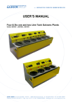
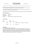
Notes for DME64N/DME24N Version 1.2
Thank you for purchasing the DME64N/DME24N. The following notes supplement the information in the Owner’s Manual
about DME64N/DME24N.
Upgrading Cautions
• The following parameter will not be reflected in Version 1.2 when it is used to read data created in Version 1.0.0: SlotIn/SlotOut.
Remake these settings in DME Designer Version 1.2.
• Data created using Version 1.2 will not open properly on Version 1.1.
• Version 1.2 will not work with previous version in the area. When using Version 1.2, all DME firmware (program and components),
along with DME Designer, must be upgraded to Version 1.2 simultaneously. For instructions on performing the version upgrade,
see “DME Firmware Update” in Chapter 3 “Main Panel Window” of the “DME Designer Version 1.2 Owner’s Manual.”
• To use the DME CONTROL function on the PM5D, the PM5D must be version 1.12 or later, and connected DME64N/24N units
must be version 1.1 or later.
• For details about DME CONTROL function settings in the PM5D, see the “PM5D/PM5D-RH Owner’s Manual.”
Changes in Version 1.2
■ An Edit Indicator has been added.
If a parameter is changed after recalling a scene, a dot
will appear in the scene number indicator, and “EDIT”
will appear in the display.
■ The User-defined parameters display is changed.
“No Assign” settings in DME Designer are displayed as
dotted lines.
When [Parameter Value Edit] is selected the display will
be a solid line.
When [Direct Parameter Value], [Scene Change], [GPI
Out], or [Play Wav File] are selected, the display will be
inverted.
■ The Remote parameter has been added to Utility display “Misc” page.
• The REMOTE connector can be used as a MIDI connector.
• A new communications protocol allows AMX, Crestron, and other external devices to control the DME.
For details about the communication protocol refer to the “DME-N Remote Control Protocol Specifications” document.
The “DME-N Remote Control Protocol Specifications” document can be found at the Yamaha Pro Audio website:
http://www.yamahaproaudio.com/
HA Control (422)
External head amp control (RS-422 only)
COM (232C)
Control using the DME communication protocol via RS-232C/RS-422.
COM (422)
MIDI (232C)
Control using MIDI commands via RS-232C/RS-422.
MIDI (422)
Remote Ctrl (232C)
Remote controller via RS-232C/RS-422.
Remote Ctrl (422)
Added parameters are shown in bold.
EN
Changes in Version 1.1
For information on changes to DME Designer, see the “DME Designer Version 1.2 Owner’s Manual.”
■ The default gateway IP address is changed.
In Version 1.0, the default IP gateway address was ***.***.***.1, but in Version 1.1, the address is changed to ***.***.***.254.
Consequently, while the zone slave IP addresses in Version 1.0 were ***.***.***.3 through ***.***.***.254, they have changed
in Version 1.1 to ***.***.***.3 through ***.***.***.253.
■ An initialization function has been added.
With this function you can initialize the DME64N/24N and the ICP1.
Turn the power OFF, then turn it back on again while holding down the [SCENE] and [ENTER] buttons.
SCENE
HOME
UTILITY
LEVEL
MUTE
CANCEL
ENTER
1. Holding down the [SCENE] and [ENTER] buttons
2. Press the [POWER] button
Plug the PA-300 AC adaptor while holding down
the [SCENE] and [ENTER] buttons.
01. Initialize DME: Returns to the factory setting. (Deletes all user settings except component data.)
02. Delete All Data: Deletes all data.
03. ==> Exit Diag Mode: Leaves this screen and restarts.
■ A THRU connection function has been added.
Even in an environment with no computer, you can check the connections without using DME Designer by directly
connecting the DME64N/24N input/output.
The meter does not operate during a connection check.
This is set on the CHECK page of the utility screen.
MODE: OFF
Makes connections in the configuration used in the current scene.
This is set to OFF when the unit is started.
MODE: Thru
Directly connects the Input and Output of each slot one-to-one for
each channel.
When input-only or output-only cards like AD or DA cards are
inserted in the slots, you cannot perform checks in this mode.
In the DME24N, the internal AD and internal DA are directly
connected on each channel.
2
Notes for DME64N/DME24N Version 1.2
MODE: Summing
Sums all input signals coming from Inputs (-12dB), without regard to
device or card type, and outputs it through all Outputs.
■ The Event Scheduler function allows day/time settings for events
The settings are accessible via the Utility display “Misc” page.
Refer to the “DME Designer Version 1.2 Owner’s Manual” for details.
Event Scheduler
Determines whether an event schedule setup in the DME Designer
will be executed or not, and displays the current status.
ON: The event will be executed.
OFF: The event schedule will not be executed.
■ A DAW control function has been added.
With this function you can control the DME64N/24N from a DAW controller.
1. Parameter Control Function
Lets you control DME64N/24N parameters using a DAW Controller.
For example, if the PAN parameter is assigned to CH1 of the DAW controller, you can control the PAN parameter by
operating a knob.
There are two modes in the parameter control function, as follows:
(1) General Parameter Operation Mode
[KNOB] and [CH FADER] controls are used to operate internal parameters assigning them in DME Designer.
For detailed settings, see the “DME Designer Version 1.2 Owner’s Manual.”
(2) Final Output Stage Parameter Operation Mode
Final output stage parameters are operated using [MUTE] and [CH FADER] controls.
Unlike the General Parameter Control Mode, controls and the parameters that are compatible with them, are fixed in this
mode.
[Method of Operation]
[▲]: Switches to General Internal Parameter Control Mode.
[▼]: Switches to Final Output Stage Parameter Control Mode.
[BANK <][BANK >]: The channels targeted for operation are shifted by the number of channels built into the DAW
controller.
[CH <][CH >]: The channels targeted for operation are shifted one channel at a time.
[SELECT]: Switches the display method on the DAW controller.
When turned OFF, an overall display appears. When a channel is turned ON, the detail display appears for that channel.
For information about the overall and detail displays, see the next item, “Setting and Parameter Name Display Function.”
[KNOB]: Changes assigned parameters in the General Internal Parameter Operation Mode.
This is not used in the Final Output Stage Parameter Operation Mode.
[MUTE]: This is not used in the General Internal Parameter Operation Mode.
This turns muting ON or OFF for the corresponding channel in the Final Output Stage Parameter Operation Mode.
[CH FADER]: Changes assigned parameters in the General Internal Parameter Operation Mode.
This adjusts volume for the corresponding channel in the Final Output Stage Parameter Operation Mode.
NOTE
Only one parameter can be assigned to the same channel.
2. Setting and parameter name display function
Displays the settings and parameter names on the DAW controller’s LCD screen.
There are two display methods: over-all display and detail display.
Overall Display: The overall display shows the assigned parameter names and settings, organized by DAW channels.
Detail Display: In the detail display, you select the parameter you want to display. Only information for that parameter
appears on the DAW controller’s LCD screen.
NOTE
The number of characters that can be displayed is limited by the size of the DRAW’s LCD screen.
Notes for DME64N/DME24N Version 1.2
3
3. User Label Function
Lets you attach names to assigned parameters.
For details about settings, see the “DME Designer Version 1.2 Owner’s Manual.”
■ A GPI LOCK function has been added.
This functions allows you to disable input from a GPI device.
For details about settings, see the “DME Designer Version 1.2 Owner’s Manual.”
■ The number of MY16-C cards that can be used simultaneously in the DME64N is now four.
In Version 1.0, only two MY16-C cards could be used simultaneously in the DME64N (page 20 in the DME64N/24N Owners
Manual). In Version 1.1, up to four cards can be used simultaneously.
However, if the serial number written on the upper surface of your DME64N is shown below, a hardware upgrade is needed.
KK, KL, KM, KN, KO, KP, KX, KY are the third and fourth digits of the serial number.
A fee is charged for the hardware upgrade.
For details, contact Yamaha customer support using the contact information located at the end of the “DME64N/24N
Owner’s Manual.”
■ The [PHONES] terminal can now be muted.
The [PHONES] terminal in Version 1.0 was not muted when the unit as a whole was muted by pressing the [MUTE] button
(page 40 in the DME64N/24N Owner’s Manual, “Mute Switching.” In Version 1.1, all outputs are muted including [PHONES].
■ The CASCADE setting (page 53 in the DME64N/24N Owner’s Manual) is now available from DME
Designer only.
In Version 1.0, CASCADE could be set in the DME64N, but in Version 2.0, this is a screen display function only.
Set CASCADE from DME Designer.
For details about settings, see the “DME Designer Version 1.2 Owner’s Manual.”
■ The monitoring function (page 42 in the DME64N/24N Owner’s Manual) has been changed.
• By editing the Monitoring Point List in DME Designer, you can select user-defined monitoring points in the DME64N/24N. Using
this function, component input/output points can be selected for monitoring points in the DME64N/24N.
• The [MONITOR] indicator blinks when you are using the probe monitor function to select monitoring points from DME Designer.
• You can turn the monitoring function OFF.
• Lighting of the indicator lamp is linked to ON/OFF for the monitoring function and probe monitoring function.
The monitoring function is for monitoring the sound at a specific point within the DME.
The monitored sound is output from the [PHONES] terminal and from the Monitor OUT that is set in DME Designer.
1. Setting a monitoring point from the DME64N/24N
You can select a monitoring point in the DME64N/24N and check the sound.
(1) Slot or user defined selection
Select the slot or User Defined in the monitoring slot dialog.
The following five position types can be selected:
1 Slot input/output terminal
2 CASCADE input/output terminal (DME64N only)
3 IN terminal (DME24N only)
4 OUT terminal (DME24N only)
5 User Defined
By connecting 1 through 4 in DME Designer, you will be able to select the input/output terminal.
You will be able to select 5 by editing the Monitoring Point List in DME Designer.
(2) Selecting a Monitoring Point
Monitoring points can be selected using the “Monitoring Point” dialog box.
The monitoring point will switch and the [MONITOR] indicator lights up.
Method of Operation
With the monitoring function set to OFF ([MONITOR] indicator not lit) press the [MONITOR] button to display the
Monitoring Slot Dialog.
In the dialog, select the Monitoring Slot and Monitoring Point and use the [ENTER] button to confirm.
Pressing the [CANCEL] button returns to the previous dialog.
4
Notes for DME64N/DME24N Version 1.2
2. Setting the Monitoring Point from DME Designer (Probe Monitor Function)
For details, see the “DME Designer Version 1.2 Owner’s Manual.”
When you use the probe monitor function, the monitoring point switches and the [MONITOR] indicator lights up.
At the same time, the “Probe” mark appears on the DME64N/24N display, and the monitoring point selected in the DME64N/
24N is disabled.
3. Monitoring OFF
You can turn OFF the monitoring function at the DME unit.
This turns OFF output of sound from the [PHONES] terminal and the Monitor OUT set in DME Designer.
Method of Operation
When the monitoring function is set to ON ([MONITOR] indicator lit steadily or blinking), you can tur n it OFF by pressing
the [MONITOR] button.
The [MONITOR] indicator light turns OFF.
When you want to turn ON the monitoring function, select a monitoring point.
The following notes supplement the information in the DME64N/DME24N Owner’s Manual:
■ Only a limited number of some components can be arranged in a configuration.
Maximum number of components that can be arranged
(for each DME unit)
Component
Matrix Mixer
64 Input 32 Output
64 Input 64 Output
DME64N
DME24N
1 (*1)
0 (Cannot be arranged)
(*1)
• Input components (Slot In, Cascade In) and output components (Slot Out, Cascade Out) cannot be directly connected.
• Components other than input/output components cannot be arranged.
■ The following notes apply when “Preparation” on page 19 of the DME64N/24N Owner’s Manual is
started up for the first time.
The meter does not operate during the first startup. The [SIGNAL][PEAK] indicators also do not work in the DME24N.
■ There is an error on page 29 of the DME64N/24N Owner’s Manual, where it states that there is
current between the OUT and GND [GPI] terminals.
Incorrect
Correct
Illustration note
Max. 6mA
Caution sentence
Make sure that the current between the OUT and Make sure that the current between the OUT and
GND [GPI] connectors is less than 6mA.
GND [GPI] connectors is less than 16mA.
Max. 16mA
■ The following notes apply to “Net Page (Network Settings Page)” on page 47 of the DME64N/24N
Owner’s Manual:
3 Link Mode
Error:
The 100Base-Tx: [NETWORK] terminal operates as 100Base-TX.
Correct: The 100Base-Tx: [NETWORK] terminal operates as 100Base-TX if possible. If the network environment does not
support 100Base-TX, it operates as 10Base-T.
■ The following notes apply to the RS-232C terminal in “Control I/O)” on page 63 of the DME64N/24N
Owner’s Manual:
Baud Rate = 38,400 bps
Data = 8bit
Stop bit = 1bit
Notes for DME64N/DME24N Version 1.2
5
Message List
Message
6
Content
Corrective Action
Cannot Select
There is no selectable item in the scene or monitoring
point list.
Data is not registered.Register the data to be used in DME
Designer.
CAS. In Sync Err
The word clock input from the [CASCADE IN] terminal is
not synchronized with the DME64N word clock.
Recheck the settings for using the word clock that
synchronizes the DME64N and external devices.
CAS. Out Sync Err
The word clock input from the [CASCADE OUT] terminal is Recheck the settings for using the word clock that
not synchronized with the DME64N word clock.
synchronizes the DME64N and external devices.
Connecting
Searching for DMEs in the network and connecting them.
—
Download Success
The DME64N/24N program update or restoration was
successful.
—
Downloading
Updating the DME64N/24N program. Do NOT turn off the
power while this display is on the screen.
—
DSP Power Shortage
To operate with all word clocks, set the word clock in DME
The audio signal is muted without being input or output,
because the DSP resources are insufficient. This message Designer to 96 kHz when creating a configuration.
may be displayed when a configuration created at 44.1 or
48 kHz is operated at 88.2 or 96 kHz.
Duplicate IP Adr.
An IP address is duplicated.
File Operating
Scene-related data (configuration, component, etc.) from
the computer is in operation. Do NOT turn off the power
while this display is on the screen.
Flash Rom Full
The flash memory used for saving data has become full.
Erase unused data such as configurations, presets, and
audio data.
Illegal MAC Adr.
This is an invalid MAC address.
Since this is likely to be a device failure, contact a Yamaha
electric sound service outlet listed at the end of this
manual (page 79).
Invalid IP Adr.
An IP address is invalid.
Set a valid IP address.
Invalid Password
The password is incorrect.
Enter the correct password. If you have forgotten the
password, contact a Yamaha electric sound service outlet
listed at the end of this manual (page 79).
Low Battery
Battery capacity is running low.
Stop using the unit immediately and contact a Yamaha
electric sound service outlet listed at the end of this
manual (page 79).
MIDI Port In Use
The USB port being used for communication with DME
Designer has been selected as a host.
Set Host on the utility screen’s MIDI page to another port.
Network Busy
Traffic in the network is congested. Communication will
take time.
Check the devices connected to the network. If there are a
large number of connected devices, reduce their number.
If LinkMode is set to 10BASE-T, traffic speed may improve
if the setting is changed to 100BASE-TX.
Network Error
Investigate the cause of the error and eliminate it.
An error like the following has occurred on the network:
• A cable has become disconnected.
• The power to a connected hub or router is cut off.
• A cable is in an unsuitable condition (such as something
heavy resting on the cable).
(Static electricity may be having an effect.)
Network Setup
Various settings for connecting to the network are being
made.
No Battery
The battery is exhausted.
When the power is turned OFF, the current settings will be
lost and the unit will return to its initial settings. Stop using
the unit immediately and contact a Yamaha electric sound
service outlet listed at the end of this manual (page 79).
No Current Scene
There is no current scene.
This is displayed when scene data has not been sent even
once. Create data using DME Designer, and synchronize
DME Designer and the DME64N/24N unit.
No MAC Adr.
No MAC address is set.
Since this is likely to be a device failure, contact a Yamaha
electric sound service outlet listed at the end of this
manual (page 79).
Panel Locked
Panel lock is set, and the panel cannot be operated.
Panel lock may have been set by the administrator to
prevent unexpected data changes caused by erroneous
user operations.
To use the panel, hold the [CANCEL] button down for at
least two seconds. This clears the panel lock.
Panel Unlocked
Panel lock has been cleared. Panel operations are
possible.
Param Access Err
Cannot display current settings.
The component version may be old. Update to the latest
component.
Param Set Err
Cannot change current settings.
The component version may be old. Update to the latest
component.
Notes for DME64N/DME24N Version 1.2
Change the settings so that there are no duplicate IP
address.
—
—
—
Message
Content
Corrective Action
Recovering
The DME64N/24N program update has failed. Restoring
the previous program. Do NOT turn off the power while
this display is on the screen.
Retry the program update. If the update is still
unsuccessful after several retries, a malfunction is likely.
Contact a Yamaha electric sound service outlet listed at
the end of this manual (page 79).
Saving Failed
Cannot save settings.
Since this is likely to be a device failure, contact a Yamaha
electric sound service outlet listed at the end of this
manual (page 79).
Saving HA Info
Saving head amp information. Do NOT turn off the power
while this display is on the screen.
—
Saving Setup Info
Saving information (except head amp information) that is
set in the utility screen. Do NOT turn off the power while
this display is on the screen.
—
Scene Recalling
Recalling a scene.
—
Scene Storing
Storing a scene. Do NOT turn off the power while this
display is on the screen.
—
SLOT1 Sync Err
The word clock input from Slot1 is not synchronized with
the DME64N/24N word clock.
Recheck the settings for using the word clock that
synchronizes the DME64N/24N and external devices.
SLOT2 Sync Err
The word clock input from Slot2 is not synchronized with
the DME64N word clock.
Recheck the settings for using the word clock that
synchronizes the DME64N and external devices.
SLOT3 Sync Err
The word clock input from Slot3 is not synchronized with
the DME64N word clock.
SLOT4 Sync Err
The word clock input from Slot4 is not synchronized with
the DME64N word clock.
Slots Overloaded
The electric current being consumed by cards currently
installed in the slots exceeds the specified value.
This combination cannot be used. Check the combination
of cards that are currently installed.
Store Disable
Scene storing is currently prohibited in the settings.
This prohibition may have been set by the administrator to
prevent unexpected data changes caused by erroneous
user operations.
Change the setting by going to the Misc page of the utility
screen and changing the setting for Scene Store to
“Enable.”
WCLK Unlocked
A valid word clock is not being input or cannot be
detected.
Recheck connections and internal settings related to the
word clock.
Zone Sync Err
Data from the wrong zone has been input or data has not Use DME Designer to resend the data.
been input.
NOTE
For information about updated CD-ROM versions to be released in the future, contact the store where you purchased the device, or contact
Yamaha customer service using the contact information at the end or your “DME64N/24N Owner’s Manual.”
Notes for DME64N/DME24N Version 1.2
7
The following notes supplement the information in the DME64N/DME24N Owner’s Manual
DME24N ANALOG INPUT CHARACTERISTICS
Terminals
Gain
CH INPUT -60dB
1–8
10dB
Actual
Load
Impedance
3kΩ
For Use
With
Nominal
50 – 600Ω
Mics &
600Ω
Lines
Total Harmonic Distortion fs=96kHz
Input
Input Level
Max.
Nominal before
clip
-60dBu
(0.775mV)
10dBu
(2.451V)
-40dBu
(7.75mV)
30dBu
(24.511V)
Connector
CH INPUT
1–8
Euroblock
• 0dBu = 0.775 Vrms
• All AD converters (CH1-8) are 24-bit linear, 128 times oversampling.
• +48V DC (phantom power) is supplied to CH INPUT (1-8) connectors via each individual
controlled switch.
Internal
OSC
Output
CH
OUTPUT
1–8
PHONES
RL
Conditions
600Ω
GAIN = -60dB
@20Hz – 20kHz
@+14dBu
GAIN = +10dB
@20Hz – 20kHz
@+14dBu
-30dBFS @1kHz,
phones level control:
max.
8Ω
Min.
Typ.
Max.
Units
0.1
%
0.05
%
0.1
%
Hum & Noise EIN = Equivalent Input Noise
Input
DME64N ANALOG OUTPUT CHARACTERISTICS
Output
Terminals
PHONES
Actual
Source
Impedance
For Use With
Nominal
15Ω
8Ω
40Ω
CH INPUT
1–8
Output Level
Max. before
clip
RL
600Ω
Connector
Nominal
75mW
65mW
Output
CH
OUTPUT
1–8
150mW
150mW
Stereo
Phone Jack
600Ω
• 0dBu = 0.775 Vrms
• Stereo Phone Jack = unbalanced (Tip = LEFT, Ring = RIGHT, Sleeve = GND)
Internal
OSC
DME24N ANALOG OUTPUT CHARACTERISTICS
Output
Terminals
OUTPUT
1–8
PHONES
Actual
Source
Impedance
For Use With
Nominal
150Ω
600Ω Lines
15Ω
8Ω
40Ω
Output Level
Max. before
Nominal
clip
+4dBu
(1.23V)
75mW
65mW
Connector
+24dBu
(12.28)
150mW
150mW
Euroblock
• 0dBu = 0.775 Vrms
• All AD converters (CH1-8) are 24-bit linear, 128 times oversampling.
• Stereo Phone Jack = unbalanced (Tip = LEFT, Ring = RIGHT, Sleeve = GND)
8Ω
Min.
Typ.
Max.
Units
-128
EIN
dBu
-64
dBu
-82
dBu
-86
dBu
• Hum & Noise are measured with a 6dB/octave filter @12.7kHz; equivalent to a 20kHz filter
with infinite dB/octave attenuation.
Dynamic Range
Input
Stereo
Phone Jack
PHONES
Conditions
GAIN = -60dB
Master fader at
nominal level and
one Ch fader at
nominal level.
(Mixer mode)
GAIN = +10dB
Master fader at
nominal level and
one Ch fader at
nominal level.
(Mixer mode)
Residual output
noise, phones level
control: min.
CH INPUT
1–8
Output
CH
OUTPUT
1–8
RL
600Ω
Conditions
Min.
GAIN = +10dB
Typ.
Max.
106
Units
dB
• Dynamic range are measured with a 6dB/octave filter @12.7kHz; equivalent to a 20kHz filter
with infinite dB/octave attenuation.
Crosstalk@1kHz
From/To
DME24N ANALOG CHARACTERISTICS
(Output impedance of signal generator: 150Ω)
CH N
Frequency Response 20Hz – 20kHz, reference to the nominal output level
@1kHz
Input
CH INPUT
1–8
Internal
OSC
Output
CH
OUTPUT
1–8
PHONES
RL
600Ω
Conditions
GAIN = -60dB
8Ω
Min.
Typ.
Max.
Units
-1.5
0.0
0.5
dB
-3.0
0.0
0.5
dB
To/From
CH (N-1) or
(N+1)
Conditions
Internal
OSC
Max.
-80
Units
dB
Maximum Voltage Gain@1kHz
Input
CH INPUT
1–8
Output
CH
OUTPUT
1–8
RL
600Ω
Conditions
Min.
GAIN = -60dB
Output
Input
Typ.
Typ.
Max.
64
Units
dB
Phantom Voltage
Frequency Response fs = 96kHz@20Hz – 40kHz, reference to the nominal
output level @1kHz
CH INPUT
1–8
Min.
CH1 – 8, adjacent
inputs
Output
CH
OUTPUT
1–8
PHONES
RL
600Ω
Conditions
GAIN = -60dB
Min.
Typ.
Max.
hot, cold: No load
Min.
46
Typ.
48
Max.
50
Units
V
Units
-1.5
0.0
0.5
dB
-3.0
0.0
0.5
dB
PEAK/SIGNAL Indicator Level
Input
8Ω
Conditions
CH INPUT
1–8
CH INPUT
1–8
Output
CH
OUTPUT
1–8
Conditions
Min.
GAIN = +10dB PEAK
19
red LED: ON
GAIN = +10dB SIGNAL -18
green LED: ON
Typ.
Max.
Units
21
23
dBu
-16
-14
dBu
Gain Error @1kHz
Input
CH INPUT
1–8
Internal
OSC
Output
CH
OUTPUT
1–8
PHONES
RL
Conditions
Min.
Typ.
Max.
Units
600Ω
GAIN = -60dB
GAIN = +10dB
2.0
2.0
4.0
4.0
6.0
6.0
dBu
dBu
8Ω
-30dBFS @1kHz,
phones level control:
max.
-2.0
0.0
2.0
dBu
Total Harmonic Distortion fs = 48kHz
Input
CH INPUT
1–8
Internal
OSC
Output
CH
OUTPUT
1–8
PHONES
RL
Conditions
600Ω
GAIN = -60dB
@20Hz – 20kHz
@+14dBu
GAIN = +10dB
@20Hz – 20kHz
@+14dBu
-30dBFS @1kHz,
phones level control:
max.
8Ω
Min.
Typ.
Max.
Units
0.1
%
0.05
%
0.1
%
U.R.G., Pro Audio & Digital Musical Instrument Division, Yamaha Corporation
© 2005 Yamaha Corporation Printed in Japan