1
INSTALLATION AND OPERATING
INSTRUCTIONS
442 443 452 453
482 483 462 463
WARNING
Improper installation, adjustment, alteration, service, or maintenance can
cause injury or property damage. Refer to this manual. For assistance or
additional information consult a qualified installer, service agency, or the
gas supplier.
Contents
Safety Precautions .............................................. 2
Extended Service Protection Plan ...................... 4
Ventilation Requirements .................................... 5
Installation Instructions........................................ 8
Decorative Door Panel Installation.................... 11
FOR YOUR SAFETY
Do not store or use gasoline or other
flammable vapors and liquid in the vicinity of this or any other appliance.
Reversing Door Swing ...................................... 11
Lighting and Start-Up Instructions..................... 14
Operating and User Instructions ....................... 15
Refrigerator Maintenance.................................. 17
FOR YOUR SAFETY
If you smell gas:
1. Open windows
2. Do not touch any electrical
switches
3. Extinguish any open flame
4. Immediately call your gas supplier
Trouble Shooting................................................19
Failure of Refrigerator ....................................... 20
Replacement Parts............................................ 20
Wiring Diagrams................................................ 21
Warranty ............................................................ 23
These refrigerators are designed to operate on the following energy sources:
LP GAS OPERATION - 11.0 inches Propane & 12 volt DC control voltage (15.4 volts max., 10.5 volts min.).
AC OPERATION - 120 volts AC (132 volts max., 108 volts min.) and 12 volt DC control voltage.
DC OPERATION - [3-WAY MODELS] 12 volts DC (15.4 volts max., 11.5 volts min.).
Operation where these specifications are exceeded will void the refrigerator warranty.
MODEL NO. ______________________________
SERIAL NO. ______________________________
The refrigerator’s model number and serial number are on the serial plate located in the refrigerator.
Part No.: 618484B (95-09)
Safety Precautions
Read this manual and become thoroughly acquainted with it before installing or starting
the refrigerator. The following safety precautions and recommendations contained herein
are for your protection.
Improper installation, adjustment, or operation can cause injury or property damage.
The safety symbols used in this manual contain Safety Alert information. Understand their
meanings and be safety conscious.
DANGER
A SITUATION WHICH, IF NOT AVOIDED, WILL RESULT IN DEATH OR SERIOUS INJURY.
WARNING
A SITUATION WHICH, IF NOT AVOIDED, COULD RESULT IN DEATH OR SERIOUS INJURY.
CAUTION
A SITUATION WHICH, IF NOT AVOIDED, MAY RESULT IN MINOR OR MODERATE INJURY.
General
• Keep the unit and surrounding area clean. Never use the area behind refrigerator for
storage; in particular, storing flammable materials (oily rags, paper, aerosol cans,
and chemicals.). Stored materials not only present a safety hazard but could block
the ventilation to the system.
• Provide appropriate fire extinguishers installed in convenient locations. Consult your
local fire department for the correct type to use. Do not use foam on electrical fires.
Use extinguisher rated by NFPA.
• Make sure all fasteners, supports, seals, electrical covers are secure.
LP Gas System
• LP gas is highly flammable. Gas connections must be leak tight. Do not smoke,
create sparks or use an open flame when checking gas connections. Do not ignore
the "rotten egg" smell of gas fumes.
• Protect all gas lines from physical damage, vibration, or excessive heat.
• Insure that the supply gas pressure is within the tolerance specified on the front
cover of this manual. The gas controls are designed for safety. Never tamper with
the adjustment or function of the controls other than as directed by the Lighting and
Shutdown Instructions. All repairs must be done by a qualified service person.
Exhaust Gases
• Proper ventilation to remove exhaust gases is extremely important. These gases,
generated in the GAS mode at the rear of the refrigerator, replace the oxygen in the
air and in extreme cases can produce dangerous levels of carbon monoxide. This
manual contains installation instructions to safely remove the exhaust gases and
seal the zone from the living area. The installation instructions are certified by American Gas Association and Canadian Gas Association and must be followed.
• Check the burner for proper flame characteristics at the initial start-up and at least
once every year. The information for this check is located in this manual and must
be performed by a qualified service person.
2
Safety Precautions -
continued
Electrical Circuits - AC and DC
• The 120 volt AC circuit must be properly grounded. Never cut or remove the round
grounding prong from the refrigerator’s AC cord. Do not use a two-prong adapter. Do
not use an extension cord to connect to the approved AC receptacle.
• Protect all wiring from physical damage, vibration, or excessive heat.
• Always disconnect both AC and DC sources of power when working on either circuit
(only a qualified service person).
• Insure all terminating connections are clean and tight to prevent arcing or overheating.
• Never allow Leak Detecting fluids or any other liquids to spill on electrical connections. Many liquids are electrically conductive and could cause serious arcing damage and, in some case, fires.
Refrigerant System
• Never physically bend, drop, drill, weld, or hammer the refrigerant system. Doing so
could cause the system to rupture and release dangerous chemicals which can
cause severe burns to the eyes or skin. If ignited, these chemicals will burn with
intense flame. A leaking system can release certain chromium components which, if
inhaled, can cause cancer.
• Never apply direct heat in excess of 240° F to the refrigerant system. Because the
refrigerant is hermetically sealed under pressure, a temperature sensitive safety device opens to protect the system from erupting under excessive pressure. However,
the expelled refrigerant could ignite and burn if an ignition source were near.
• Never attempt to repair or recharge the refrigerant system. If defective, it must be
replaced.
Child Entrapment
• Never install door locks or other restraints which could entrap small children within
the refrigerator. The Travel Latch system must not be modified.
Handling the Refrigerator
• Never lift the refrigerator without assistance. Protect yourself from body strain.
• Avoid hot surfaces at the rear of the refrigerator when operating. The absorption
type refrigerator produces several hot areas at the rear of the unit. This is true
whether in GAS or ELECTRIC mode.
• Take care to avoid brushing against the irregular shapes and sheet metal parts at the
rear of the refrigerator. Cuts or abrasions could result.
3
E.S.P.
EXTENDED COOLING UNIT SERVICE PROTECTION PLAN
An additional four year Service Contract is now
available to original purchasers of Norcold refrigerators. For only $40.00 you get:
the original purchaser. The contract provides replacement of a defective cooling unit only for this
refrigerator (freight, parts, and labor) for an additional period of four years after expiration of the
original Limited Warranty. The refrigerator must be
delivered to Norcold Service Center together with
the Norcold E.S.P. card showing E.S.P. coverage.
An E.S.P. card will be mailed to the original purchaser upon receipt of a completed Service Contract Application form and a check covering the
E.S.P. charge. E.S.P. coverage is non-transferable and non-refundable.
To register your refrigerator, fill out the warranty
Service Contract Application - i.e.: Tear Sheet
Form in yellow envelope or include the following
information (Please Print Clearly):
* Four extra years protection against cooling unit
failure.
* Automatic replacement of defective cooling unit.
* Pre-paid freight from your dealer to Norcold and
return.
* Labor free of charge.
The E.S.P. (Extended Service Protection) plan
can be obtained by mailing your check for $40.00*,
U.S. funds to:
1.
2.
3.
4.
5.
6.
NORCOLD
P O BOX 4248
SIDNEY OH 45365-4248
If mailing in Canada:
GREG LUND PRODUCTS LTD
P O BOX 760
OAKVILLE ONTARIO CANADA L6J 5C4
E.S.P. is a service contract between Norcold and
Owner’s name and address.
Refrigerator model number.
Refrigerator serial number.
Date of purchase.
Refrigerator proof of purchase
Check for $40.00* (payable to Norcold).
Applications will be accepted only if they are mailed
within ninety (90) days after date of purchase.
*Ohio residents, add $2.60 sales tax.
Keep the refrigerator and the surrounding area clear
and free of combustible materials, gasoline, and
other flammable materials.
General Instructions - All Models
The refrigerators described in this manual are designed for built-in installations and require cut out dimensions as indicated on page .
The refrigerators must be placed on a solid and
level floor away from heat generating sources. The
floor must be strong enough to support the combined
weight of the refrigerator and its food load.
Never install the refrigerator directly on carpeting.
To protect carpeting, the refrigerator must be placed
on a metal or wood panel extending at least the full
width and depth of the refrigerator.
Note:
4
These appliances are not approved for
use as a Free-Standing refrigerator. The
refrigerator must be used in the manner
for which it was designed. Refer to this
manual for installation, operating procedures, and the refrigerator intended use.
This appliance is equipped for LP gas
and cannot be converted to any other fuels (Natural Gas, Butane, etc.).
VENTILATION REQUIREMENTS
WARNING: Carbon Monoxide can cause
nausea, fainting, or death. Inadequate ventilation or partial blockage of the refrigerator’s flue can result in increased carbon
monoxide emissions when operating in the
gas mode. To prevent the emission of levels of carbon monoxide, installation must
assure complete isolation of the living
space of the R.V. from the refrigerator’s
combustion system. Follow Norcold’s Ventilation and Installation recommendations
explicity.
The vents for these refrigerators are certified by
A.G.A. and CGA and must be installed as directed
by this manual without modification. Any deviation
or substitution:
* Can result in carbon monoxide levels in the living
space of the vehicle.
* Will void the agencies’ certification.
* Will void the refrigerator warranty.
* Will effect refrigerator performance.
The intake vent (lower) also serves as a access
(service entrance) door. The bottom of the intake
vent opening must be flush with the surface on which
the refrigerator is mounted. This configuration allows
any leaking propane to ventilate to the outside.
A.G.A. And CGA certification permits installing the
refrigerator with zero (0) inches minimum clearance
between the refrigerator and any adjacent walls. This
certification does not specify any maximum clearance. However, to insure adequate air flow across
the cooling system, the clearance must be minimized. The combination of the two vents and the
minimum clearances provide the necessary air flow
through the creation of a natural draft, or "chimney
effect" across the cooling system.
Venting is required in an R.V. refrigerator installation to remove the products of combustion, to isolate
the living space of the vehicle from the combustion
system of the refrigerator, to remove the excess heat
from the generator area of the refrigerator’s cooling
system, and to remove the heat that is extracted
from the refrigerator cabinet.
Certified installation requires that one intake (lower)
and one exhaust (upper) be used. For the models
6052, 6053, 652, and 653, the installer has the option of exhausting through the roof or through an upper side wall vent. Whether roof or side wall exhaust
venting, the specified vent kit must be installed as
directed by this manual. To insure adequate refrigerator performance, a continuous air flow is required
across the refrigerator’s cooling system.
The air passage from the intake vent to the refrigerator coils and from the refrigerator coils through the
exhaust vent must be unobstructed.
Certified Vent Kits
Kit Number
Certified Lower
Vent Door
Certified
Roof Jack
Models
2&3
615998
616009
616010
617778
615791
All Models
Kit Number
Certified Lower
Vent Door
Certified
Upper Side
Exhaust
Models
4
615998
616009
616010
617778
617485
442. 443
452, 453
ONLY
TABLE 1
DIMENSIONS (INCHES) for Vent Kits 2, 3, and 4
Cut - Out Dimension (inches)
Roof Jack
Part No.
Type
Length
Width
Height
Width
Radius
Approved
Models
617778
Plastic
--
--
13 3/4
21 1/2
--
All Models
616010
Sq. Corner
--
--
13 3/4
21 3/4
--
All Models
616009
Rad. corner
--
--
13 3/4
21 7/8
3 1/4
All Models
615998
Rad. Corner
--
--
13 3/4
21 7/8
3 1/4
All Models
Upper Side
vent
--
--
7 1/4
18
--
6052, 6053
652, 653
Roof Jack
24
5 1/4
--
--
--
All Models
85
615791
Lower Intake Vent
5
1
3
2
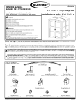
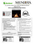
Optimum Installation - Figure 1
The optimum installation is illustrated in Figure 1.
Condenser
(source of
rejected heat)
1. Area above refrigerator blocked (baffled) off to
prevent trapping of hot air above the refrigerator.
2. 0 -1/4 inch clearance at the top of the refrigerator.
3. Exhaust vent centered directly over refrigerator’s condenser.
4. 0 - 1 inch at rear of the refrigerator.
5. 0 inch clearance at bottom of refrigerator.
4
Absorber
(source of
rejected heat)
5
Air flow path
Figure 1
Exhaust vent opening
centered over condenser
(front to rear of vehicle)
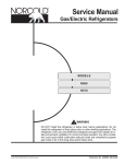
Exhaust Vent Centered - Figure 2
Figure 2 further illustrates the requirement to center
the exhaust vent opening over the condenser of the
refrigerator.
.
Figure 2
Alternate
Figure 3
1
2
2
Construction
Requirements
1. Exhaust vent opening is inboard in relation to
the rear of the refrigerator.
2. Baffles added to the top of the refrigerator to
assist in directing air flow out the exhaust vent.
3. 0-1/4 inch clearance at the top of the refrigerator.
4. Angle between baffles and rear top edge of the
refrigerator not to exceed 45 degrees.
5. Deflectors added at rear in strategic locations
adjacent to the cooling units condenser and absorber coils to reduce clearance to 0 to 1 inch.
3
4
Condenser
5
Absorber
Figure 3
6
Side Wall Clearance - Figure 4
1. Figure 4 illustrates the requirement to minimize
the clearance at the sides of the refrigerator.
The clearance is not to exceed 1/2 inch. Side
clearances in excess of 1/2 inch must be either
filled with Fiberglas batting or blocked with paneling, etc.
B
1
1
Figure 4
Upper Side Wall Exhaust Vent For Models 452, 453, 442, and 443 ONLY
Figure 5
1
2
1. Area above refrigerator blocked (baffled) off to
prevent trapping of hot air above the refrigerator.
2. 0 - 1/4 inch clearance at the top of the refrigerator.
3. Upper Side vent Location. Floor level to top of
opening. 38 1/8" for models 442 & 443. 50 1/2"
for models 452 & 453. See Table 1 for vent
dimensions,
4. 0 - 1 inch clearance at the rear of the refrigerator. (See Figure 3 when clearance exceeds 1
inch).
5. Intake (lower) vent installed flush with the surface on which the refrigerator is mounted.
6. O inch clearance at bottom of refrigerator.
4
3
6
5
Figure 5
1
Top and Side Wall Clearance-All Models
Figure 6
1. Top baffle fills the total area above the refrigerator an is properly aligned with the side wall
construction.
2. 0 - 1/2 inch at the sides of the refrigerator.
2
Figure 6
7
2
INSTALLATION INSTRUCTIONS
Certification and Code Requirements
Combustion Seals
The refrigerators described herein are certified under the latest edition of ANSI Z21.19 Standards by
the American Gas Association (A.G.A.) for installation in mobile home or recreational vehicle and approval by the Canadian Gas Association (CGA).
Installation must be made in accordance with these
standards and with the installation instructions provided in this manual for the Norcold factory warranty
to be in effect.
Installation must conform with local codes, or in the
absence of local codes, with the following standards
as applicable:
In the United States:
a. National Fuel Gas Code, ANSI Z223.1.
b. Manufactured Home Construction and Safety
Standard, Title 24 CFR, Part 23-80.
c. Standard for Recreational Vehicles,ANSI
A119.2, latest edition.
When an external electrical energy is utilized, the
refrigerator must be electrically grounded in accordance with local codes, or in the absence of local
codes, the National electrical Code, ANSI/NFPA 70.
In Canada:
a. Current CGA B149.1 and B149.2 installation
code for Propane Appliances and Equipment..
b. Current CSA Z240.4.2 installation code for Propane Appliances and Equipment in Recreational Vehicles.
c. Current CSA Z240.6.2/C22.2 No. 148 Electrical
Requirement for Recreational Vehicles.
When installed, the appliance must be electrically
grounded in accordance with the current Canadian
Electrical Code C22.2 Parts 1 and 2.
Combustion seals (foam strips) are attached to the
back surface of the refrigerator’s mounting flanges.
These seals isolate the products of combustion from
the vehicle’s living space. The seals must be continuous between the wall and the mounting
flanges to assure a complete combustion seal.
When installing or removing the refrigerator, insure
that the seals are not missing or damaged.
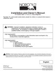
Lower Flange Installation
The lower mounting flange and mounting screws
are located in a clear plastic bag positioned in the
coils at the rear of the refrigerator. After removing the
plastic bag, slide the refrigerator partially into the enclosure and attach the lower mounting flange. Install
the lower mounting flange by maneuvering it under
the bottom control cover and secure with the screws
provided. Refer to Figure 7. Do not omit installation of the lower mounting flange. This flange is
part of the combustion seal.
Cut-Out Dimensions
The refrigerators certified for built installation and
requires cut-out dimensions as indicated in Table 2
below.
Figure 7
TABLE 2
REFRIGERATOR CUT-OUT OPENINGS (INCHES)
Model
462, 463
482, 483
452,453
442,443
Height
52 7/8
59 7/8
43 1/4
30 7/8
Width
23 1/2
23 1/2
23 1/2
23 1/2
Securing the Refrigerator
Depth
24
24
24
24
Secure the refrigerator with screws through the
mounting flange holes at the front of the refrigerator
and the holes at floor level at the rear of the refrigerator. Screw covers are provided to cover the front
mounting flange holes.
8
Gas Connection
The refrigerators are designed to operate on propane gas at a supply pressure of 11 inches water
column. A pressure regulator is required between the
refrigerator and the main gas tank. Do not connect
the refrigerator directly to the main propane tank
without a pressure regulator.
Use supply piping and fittings that comply with local,
state, and national codes governing type and size.
These components should also comply with NFPA
501C. Flexible metal connectors must comply with
the current CAN 1-6.10 Standard. To prevent gas
pressure loss to the refrigerator, the propane should
be supplies by a 3/8 inch diameter copper piping.
The gas supply piping is connected to the refrigerator
by means of 3/8 inch SAE (UNF 5/8 - 18) male flare
fitting.
Route the gas supply piping to limit vibration and
abrasion. The gas supply piping should enter the refrigerator enclosure near the gas connection at the
rear of the refrigerator. The hole through which the
gas piping enters should be of sufficient size (approximately 1/2 inch diameter) to provide adequate
clearance for the piping. Once the gas piping is in
place, apply a sealant around the piping at its point
of entry to minimize abrasion and vibration, and to
serve as a barrier to external moisture.
Figure 9 Rear View
120 Volt AC Connection
WARNING: The refrigerators are designed
to operate on a 120 volt, 60 Hertz
grounded AC circuit. The refrigerator’s AC
power cord is equipped with a three-prong
grounding plug which must mate with a
three-prong grounded receptacle to protect
against possible electrical shock hazards.
Operating the refrigerator without proper
ground can cause property damage, severe personal injury, or death. It is the installer’s responsibility and obligation to
provide a properly grounded electrical circuit to the refrigerator accordance with local codes, or in the absence of local
codes, the National Electrical Code,
ANSI/NFPA 70. Do not cut or remove the
round grounding prong from the refrigerator’s AC power cord. Do not use a two
prong adapter or an extension cord.
CAUTION: Use two wrenches when manipulating the gas inlet fitting. Failure to
use two wrenches can over stress the piping and create gas leaks.
Manual Shut-Off Valve
Hold
3/8 " Gas Supply
The free length of the refrigerator’s AC power cord
is 24 inches. It is recommended that the three-prong
grounded receptacle be located to the left side of the
refrigerator (viewed from rear) and approximately 12
inches from the floor (see Figure 9 above). The AC
power cord must be routed so as not to contact the
refrigerator’s burner, flue pipe, or any other component which could damage the cord insulation.
Turn
Figure 8
The gas supply is connected to the refrigerator at
the inlet to the manual gas valve located at the bottom rear of the refrigerator. Access to this area is
obtained through the vehicle’s lower vent door. Care
must be taken when connecting the gas piping to the
refrigerator to insure the fittings are secure.
12 Volt DC Connection
A 12 volt DC supply is required to maintain the
flame ignition circuit in the gas mode and for 3-Way
models, to provide power for the DC heater. The DC
9
supply connects to the terminal block at the rear of
the refrigerator (See Figure 9 on page 8). The 12 volt
DC should enter the refrigerator’s enclosure near the
refrigerator’s terminal block. The 12 volt DC connects
at (2) one quarter inch quick connects. The positive
DC input lead connects to terminal marked (+), and
the DC ground input lead connects to terminal
marked (-).
tional Electric Code (ANSI/NFPA No. 70, Art. 551).
When this conductor is used to bond the non-current
carrying metal parts of the refrigerator, a No. 10-32
bonding terminal is provided to make the connection.
(See Figure 10 ).
CAUTION: Correct polarity must be observed when connecting the DC supply.
Do not use the chassis of the refrigerator
or the vehicle frame as one of the conductors. Connect DC supply wires at the battery and route to the refrigerator.
The distance the current travels from the battery to
the refrigerator dictates the wire size. Undersized
wire can result in a voltage drop, which will affect the
wattage output of the DC heater and result in reduced refrigerator performance. Norcold recommends
the installation of a fuse in the supply wiring between
the battery and the refrigerator. For optimum protection, install the fuse as close to the battery as possible.
WARNING: A circuit overload can result in
an electrical fire when undersized wires or
improperly sized fuses are used. To prevent a possible electrical fire, follow
R.V.I.A. A119.2 Standards, Norcold’s wire
size and fuse specifications, or applicable
state and local codes.
TABLE 3
12 VOLT SUPPLY WIRING AND FUSE SIZE
482, 462
452, 442
483, 463
453, 443
min.
wire
size
max.
fuse
size
Min.
wire
size
max.
fuse
size
0 - 20’
18 6 Amp 10
AWG
AWG
30
Amp
12
AWG
20
Amp
over
20’
18 6 Amp
8
AWG
AWG
40
Amp
10
AWG
30
Amp
min.
wire
size
max.
fuse
size
If a wire size is installed which is larger than the
minimum size indicated the table above, it must be
fused in accordance with the R.V.I.A. A119.2 standard or local governing codes.
Chassis Bonding Connection
A No. 8 AWG copper conductor is commonly used
to meet the chassis bonding requirements of the Na-
Figure 10
Hypot Test
A Dielectric Strength test (hypot) has been conducted at the factory; this refrigerator does not require an additional test. If hypot tests are conducted
on the vehicle’s 12 volt circuit, the 12 volts must be
disconnected from the refrigerator to protect the
flame ignition circuit.
Testing the Vehicle’s Gas Supply Piping
When installation of the refrigerator is complete, the
propane gas supply piping must be inspected and
tested for leaks from the refrigerator to the main gas
supply tank. Use a leak detection solution. Do not
test for leaks with an open flame.
If compressed air is used for leak testing, the gauge
pressure must not exceed 1/2 pound per square inch
(14 inches water column).
The appliance and its individual shut-off valve (Figure 11 on page 10) must be disconnected from the
gas supply system during any pressure testing of that
system at test pressures greater than 1/2 psig (14
inches water column).
The appliance must be isolated from the gas supply
system by closing its individual manual shut-off valve
(Figure 11 on page 10) during any pressure testing
of that system at test pressure equal to or less than
1/2 psig (14 inches water column).
Check the gas pressure to the refrigerator without
other gas appliances operating. The pressure should
not exceed 11 inches water column. With other appliances operating the pressure should not be less than
10.5 inches water column.
10
Figure 12
INSTRUCTIONS
1. Prepare panel by cutting to size indicated in accompanying chart. (See TABLE 4)
2. Remove handle assembly (A) by removing four
screws (B). (See Figure 12)
3. Slide panel into frame slots.
4. Replace the handle assembly.
Figure 11
Check Out - Flame Failure Safety Device
Before placing the refrigerator into operation, the
gas safety device must be tested (see Operating Instructions on page 13). The purpose of the gas
safety device is to prevent the escape of unburned
gas from the burner if the burner flame is extinguished. Once a flame is established, close the manual shut-off valve of the refrigerator. The flame will
extinguish and ignition spark will continue. Wait a
minimum of four (4) minutes and re-open the manual
shut-off valve. The burner flame will not re-establish,
indicating the gas safety control is functional.
Instructions for Reversing Door Swing
Your refrigerator is equipped with convertible door
hinges. The hinging of the doors can be changed to
the opposite side anytime you wish.
TOOLS REQUIRED
Phillips Screwdriver - Size #2
Two Slotted Screwdrivers
REMOVING THE DOORS
Door Panel Installation
1. Remove all items of food, juices, etc., from the
doors. Remove the juice rack and storage bins.
Close both doors before removing hinge pins.
2. Remove the top hinge pin using one of the slotted screwdrivers. Remove the center hinge pin
(both pieces) using the two slotted screwdrivers; one on each end of the pin. Lastly, remove
the bottom hinge pin. Be sure to save the pins
for reassembly later. (See Figure 19)
The Norcold refrigerator doors provide slots for inserting decorative panels. Installation of the panels is
accomplished by removing the handle assembly, inserting the decorative panel, and re-inserting the
handle assembly. This procedure applies to both
doors. (See Figure 12)
The frame slots are designed to accept panel thickness up to 3/16" maximum.
TABLE 4
PANEL DIMENSIONS
Upper Door
462, 463
482, 483
19 11/16" x 16"
19 11/16" x 16"
Lower Door 19 11/16" x 32 1/4" 19 11/16" x 39 1/4"
Figure 13
442, 443
452, 453
3. Remove the upper door by opening the door
slightly and pulling the bottom of the door away
from the refrigerator. Allow enough room to
slide the door down off of the upper hinge pin
shoulder. (See Figure 13)
Door Panel 19 11/16" x 27 1/4" 19 11/16" x 39 1/4"
11
RELOCATING THE TRAVEL LATCHES
4 Remove the lower door by opening it slightly
and pulling the top of the door away from the
refrigerator. Allow enough room so the door
can be lifted up and off of the bottom hinge pin
shoulder (See Figure 18). Be sure to save the
hinge plates along with the spacer used in the
middle hinge bracket, for reassembly later.
(See Figures 19A, 19B, and 19C)
8. Remove both travel latches by taking out the
two screws holding each to the refrigerator.
Use the #2 Phillips screwdriver. Remove the
two screws from each of the corresponding
holes on the opposite side of the refrigerator.
Relocate them in the two holes just exposed by
the removal of the latches. Attach the latch in
the new position so the tab points towards the
opposite side of the refrigerator. Do not tighten
screws completely. (See Figure 16)
Figure 14
REMOVING
BRACKETS
AND
RELOCATING
THE
HINGE
Figure 16
5. Remove the middle hinge bracket by using the
#2 Phillips screwdriver and taking out the three
screws holding it in place. Next, remove the
three screws on the opposite side corresponding to the center hinge location. Relocate them
in the holes just exposed by the removal of the
hinge bracket. Attach the hinge bracket to the
refrigerator on the opposite side. Do not tighten
screws completely. (See Figure 15)
9. Turn the door over so that the end previously
at the bottom is now at the top. Relocate the
bottom of the door on the bottom hinge pin
shoulder. Close door and align holes in top
hinge brackets. The magnetic gasket will hold
the door in place. Before reinstalling the top
door, check to insure that the spacer is in
place. (See Figures 17 and 19C)
Figure 15
Figure 17
6. Remove the top hinge bracket and reposition it
in the opposite bottom corner. Use the same
technique as outlined in Step #5.
7. Remove the bottom hinge bracket and reposition it in the opposite top corner. Use the same
technique as outlined in Step #5.
10. Reposition the upper door in a similar manner
as described in Step #9, except the top of the
door must be engaged into the hinge pin
shoulder before setting the door in place.
(See Figure 18)
11. Starting at the top, replace the hinge pins using
the slotted screwdrivers. Tighten all screws.
12
Figure 18
A: Top Hinge
B: Bottom Hinge
C: Middle Hinge
D: Middle Hinge
Figure 19
ALIGNMENT OF THE DOORS
12. Align the upper door with the lower so that
there is a parallel gap between the doors and
around the frame. Adjust the doors to the cabinet so the gaskets seal but do not bind.
Tighten the screws holding the hinge brackets
in place.
13. Door Seal: The door seal can be checked by
closing the door on a 1" x 6" strip of paper. A
slight drag should be noticed when the paper is
pulled out from between the gasket and the
cabinet. Repeat the process around all four
sides of the door. If the door does not seal
properly, readjust the hinge brackets.
14. Position the travel latches so that they secure
the doors when closed but does not prevent
the doors from closing properly. Tighten the
two screws in each travel latch.
15. Replace the juice rack and storage bins into
the door. Make sure that the milk bins (wider
storage bins) are installed in the lowest door
position.
13
Lighting and Start Up Procedures
WARNING:
DO NOT HOLD GAS VALVE (D) IN MORE THAN 30 SECONDS. IF FLAME IS NOT INDICATED WITHIN
THIS TIME, TURN GAS TO OFF, WAIT 2 MINUTES AND RETRY. CONTINUING TO HOLD GAS VALVE IN
WILL CAUSE GAS BUILD-UP IN THE BURNER AREA AND CAN RESULT IN AN EXPLOSION WHICH
CAN CAUSE PERSONAL INJURY OR DEATH.
2-Way and 3-Way Models
Lighting Instructions: Gas Operation
(D) clockwise so that "ELEC" is visible on the
knob. Upon release, note that the knob moves
toward you, indicating that the control is locked
into electric operation.
1. Make certain that 12 Volts DC is available to
the refrigerator and divider switch is in NORMAL position.
2. Turn on gas supply at the tank.
3. Set thermostat control (C) to COLDEST setting.
4. Set ignitor switch (A) to "ON" position. The toggle light (A) located on the switch will illuminate
if 12 volts DC is present.
5. Push and rotate the "ELEC-OFF-GAS" control
(D) counter-clockwise so that "GAS" is visible
on the knob. Push the control knob (D) in and
hold until the flame indicator (B) illuminates
(continuous glow). Continue to hold approximately 5 seconds, then release. The flame indicator (B) will remain on. If not repeat this step.
NOTE: In normal use the flame should ignite
within 10 seconds. On initial refrigerator
start-up, it may take longer than 10 seconds to allow air to be purged from the
gas line, as indicated by the flame indicator (B) failing to illuminate.
Do not hold gas control valve (D) in more
than 30 seconds. See WARNING above.
6. Move thermostat control (C) to desired setting
7. The ignitor switch (A) should be left in the
"ON" position during gas operation. If the
switch is turned off, the refrigerator will cycle
normally. However, in case of flame blowout,
the relighter does not function.
Start-Up Instructions: DC Electric Operation - 3-Way models
1. Make certain that 12 Volts DC is available
to the refrigerator, divider switch is in NORMAL position, and "GAS IGNITOR" switch
(A) is "OFF".
2. Set thermostat control (C) to desired setting.
3. Set "AC-STDBY-DC" switch (E) to "DC" position.
4. Set ignitor switch (A) to "OFF" position.
5. Push and rotate the "ELEC-OFF-GAS" control
(D) clockwise so that "ELEC" is visible on the
knob. Upon release, note that the knob moves
toward you, indicating that the control is locked
into electric operation.
Operation Shut-Down: All Modes
1. Set ignitor switch (A) to "OFF" position.
2. Push and turn "ELEC-OFF-GAS" control (D)
to "OFF".
3. For longer periods of shut-down, set NORMALSTORAGE-HUMIDITY switch to STORAGE.
Operation Note: Use the "ELEC-OFF-GAS" control
(C) to shut off all cooling operation (both Gas and
Electric). The "GAS IGNITOR" switch and the "NORMAL-STORAGE-HUMIDITY" switch must be shut off
independently. The "STDBY" position of the "ACSTDBY-DC" switch (E) can be used to temporarily
shut off AC or DC operation.
Start-Up Instructions: AC Electric Operation
1. Make certain that 120 Volts AC and 12 Volts
DC are available to the refrigerator and divider
switch is in NORMAL position.
2. Set thermostat control (C) to desired setting.
3. Set ignitor switch (A) to "OFF" position.
4. Push and rotate the "ELEC-OFF-GAS" control
14
OPERATING AND USER INSTRUCTIONS
For AC electric, push and turn clockwise until the
knob is pointing to"ELEC". Note, upon release the
knob will move towards you, indicating that the operating control is locked into the AC electric mode.
Safety Valve - During the gas ignition process, the
safety valve knob must be held in until a flame is
established at the burner.
The safety valve is designed so that any loss of
flame will stop the gas flow to the burner. It is controlled by means of a thermocouple that is positioned
in the flame. As long as a flame is detected by the
thermocouple, the valve will remain open. Upon
flame failure, the valve closes, shutting off the gas
flow to the burner.
THIS APPLIANCE HAS BEEN DESIGNED FOR
STORAGE OF FOODS, STORAGE OF FROZEN
FOODS, AND MAKING ICE WHEN INSTALLED AS
DIRECTED BY THIS MANUAL.
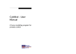
Location of Controls
Figure 18 illustrates the location of the 400 Series
refrigerator’s operating controls. All operating controls
are conveniently located below the door.
Figure 20
AC/DC Selector Switch
This switch is utilized on 3-Way models only. The
switch selects either 120 volt AC or DC electric
modes of operation. The center position of the switch
is a "Stand-By" mode which will temporarily turn off
the electric positions.
Ignition Switch
Flame
Indicator Lamp
AC/DC Selector Switch
3-Way Models Only
Gas Operation
Thermostat
The gas burner is designed to operate on propane
gas only. The gas control is equipped with an ignition
relighter, offering the features of automatic re-ignition
in case of flame blowout, positive flame sensing, and
easier gas start-up. The ignition relighter is powered
by 12 volts DC and is controlled by the ignitor switch
located on the control panel. When the switch is in
the "OFF" position, no ignition spark is present.
When the switch is in the "ON" position, the relighter
produces a rapid spark at the gas burner. The spark
occurs at a rate of 1 to 2 times per second until a
flame is present (Refer to "Lighting Instructions").
The spark continues until a flame is sensed or until
the ignitor switch is turned off. When the flame is
sensed, the relighter discontinues the spark and the
flame indicator illuminates. The flame indicator lamp
will cease to illuminate upon loss of burner flame.
During gas operation, the current draw for the re-ignition system is very low, approximately 30 milliamps
(.030 amps).
Gas On/Electric
and Safety Valve
Operating Controls Function
Ignition Switch
The ignition switch is used for the Gas operation
only. When the ignition switch is turned "ON", the
switch will illuminate indicating that 12 volt DC is
available and being supplied to the electronic ignition
which generates ignition spark to the burner.
Flame Indicator Lamp
When a flame is established at the burner, the
Flame Indicator Lamp will illuminate indicating the refrigerator is operating on gas.
Thermostat
The thermostat controls all modes of operations,
thereby eliminating the necessity of resetting each
time a different power source is selected. Rotate the
knob clockwise to make the refrigerator cabinet
colder.
120 Volt AC Operation
While parked, the coach normally operates from a
120 volt AC source. The refrigerator can be very easily switched to AC operation.
Gas ON/Electric and Safety Valve
!2 Volt DC Electric Operation
Gas ON/ELECTRIC allows the user to select an
operating mode. For gas, push and turn the knob
counter-clockwise until the knob is pointing to "GAS".
The refrigerator receives its DC power from the vehicle’s 12 volt system; either an auxiliary battery, a
converter, or the engine battery. The 12 volt DC sys-
15
Remove the bulb from its bracket. Replace the bulb
with a GE #214-2 bulb (Norcold part number
61628922), which can be purchased from most retail
automotive centers. Re-install light cover. Reconnect
the 12 volt DC.
tem not only supplies power to the refrigerator, but to
other DC components in the vehicle.
DC electric operation is not as efficient as LP Gas
or AC electric operation, and should therefore be
used only when the other modes are unavailable (for
example; while in transit - 4 to 6 hours). Reminder,
before using the DC electric mode, the refrigerator
must be cooled using either gas or electric.
Information Regarding Battery Drain
A 12 volt DC source is required for the gas mode
and the DC electric mode of operations. For the
gas operation, the DC power source supplies voltage for the electronic ignition. The current draw is
less than 30 milliamps. For models 482,3 and
462,3, if the HIGH HUMIDITY (MOISTURE REDUCTION HEATER) and the interior light were left
on, the total DC current draw would be 900 milliamps (.9 amps). This indicates that the drain on
the battery is very low and has little effect on "battery run down" unless the battery is left connected
for long periods of time without recharging.
During AC electric operation there is no battery current drain, unless the interior light or moisture reduction heater (HIGH HUMIDITY) is energized (models
482,3 and 462,3).
For the DC electric operation, the DC power source
supplies voltage for the cartridge heating element.
For models 443 and 453, the DC electric operation
draws approximately 9 amps at 12 volt DC. For models 483 and 463, the DC electric operation draws approximately 14 amps at 12 volt DC. If the battery
charging means is lost during DC operation, for instance during short stops, the refrigerator could be
switched to Gas, AC (if connected) or to the Standby
switch position until the charging means is re-established.
The DC voltage should be checked while operating
in the DC mode. The voltage at the refrigerator
should never drop below 11.5 volts.
During periods when the refrigerator is not used
(seasonal storage, etc.) the NORMAL OPERATIONSTORAGE-HIGH HUMIDITY switch should be
switched to STORAGE and the ELEC-OFF-GAS set
at OFF. This shuts off all DC drain. The Ignitor switch
must be turned off when not in use.
High Humidity - Storage Switch
Models 482,3 & 462,3 Only
Figure 21
The models 482,3 and 462,3 are equipped with a
heater that prevents moisture from forming on the
center divider between the freezer and the fresh food
compartment doors. The heater is activated by turning the NORMAL OPERATION-STORAGE-HIGH
HUMIDITY switch to the HIGH HUMIDITY position.
The switch should be left in the NORMAL OPERATION position unless condensation is observed in
this area.
When your RV is being stored for the winter, the
High Humidity - Storage switch should be placed in
the STORAGE (light off) position and ELEC-OFFGAS control to OFF. This shuts off all DC power to
the light and humidity heater and allows the refrigerator door to be left open for airing without chance of
battery drain during storage (See "Information Regarding Battery Drain")
Interior Light-Models 482,3 & 462,3 Only
The interior light is located at the top of the fresh
food compartment. The light will turn on when the
fresh food compartment door is opened and off when
the door is closed. Power to the light is activated
when the NORMAL OPERATION-STORAGE-HIGH
HUMIDITY switch is set to either NORMAL OPERATION or HIGH HUMIDITY positions.
To replace the light bulb, disconnect the 12 volt DC
from the refrigerator from the rear of the refrigerator.
Remove the light cover by sliding it towards the front
to gain access to the bulb.
Operation in Transit
While the refrigerator should be level when the vehicle is stopped, performance during transit is not
normally affected.
Refrigerator Storage Volume
CAUTION: Do not replace with a bulb of
higher wattage. Higher wattage bulbs can
damage the interior surface of the fresh
food compartment.
16
Models
Storage Volume
482,3
7.5 cu. ft.
462,3
5.9 cu. ft
Models
Storage Volume
442,3
3.1 cu.ft.
452,3
4.3 cu. ft.
erator interior. This will help to prolong the life of the
gaskets.
Leveling
Comfortable vehicle leveling is well within the refrigerator’s operating requirements of 3 degrees off
level side-to-side and 6 degrees off level front-toback (looking at the front of the refrigerator). Continued operation outside of these limits can result
in irreparable damage to the cooling system.
Door Latch
The refrigerator’s built-in door latch prevents the
door from flying open during transit. There are no
chains or slides to remember to actuate when the
vehicle starts moving (See Figure 25). Always close
the door to the sealed position (audible clicks) to prevent cooling loss and heavy frost.
Freezer Compartment
This compartment is not designed for the quick
freezing of food but designed to retain food in a frozen state. Foods purchased for storage in the freezer
compartment should be frozen when purchased to
reduce the load on the refrigerator system.
IMPORTANT: Ice trays must be placed on the
bottom freezer surface when
making ice.
Water will freeze more rapidly if the thermostat is at
it’s coldest setting.
For models 482,3 and 462,3, the freezer shelf can
be adjusted or removed to meet your storage needs.
Important Notice:
Read and understand this notice before removing this refrigerator, re-installing this refrigerator,
or performing any maintenance on this refrigerator. Norcold will not accept responsibility for improper installation, adjustment, alteration, service, or maintenance performed by anyone other
than a qualified dealer or a Norcold service center. Costs or related consequential problems resulting from improper installation, adjustments,
alteration, service, or maintenance are the refrigerator owner’s responsibility.
Fresh Food Compartment
The fresh food compartment stores and cools food.
For best cooling performance, air must be free to
circulate within the fresh food compartment. Do not
cover the shelves with paper, plastic, etc.
To reduce frost formation on the cooling fins, cover
liquids and moist foods, do not place hot foods in the
compartment, and do not leave the door open longer
than needed.
Allow the refrigerator to cool for 8 hours before
loading foods. Loading a warm refrigerator with warm
food increases the cool down period.
Refrigerator Maintenance
1. Leak test gas supply piping and fittings at least
once a year. This procedure should only be
performed by your dealer or a Norcold service
center. These facilities are familiar with gas refrigerators and propane gas systems.
2. Check the main line gas pressure periodically
and adjust if necessary. The correct input gas
pressure is 11 inches water column. It is recommended that your dealer or a Norcold service center perform this task.
3. Clean the refrigerator’s burner and burner orifice. This procedure is required once a year
minimum and should only be performed by
your dealer or a Norcold service center. These
facilities are familiar with gas refrigerators and
propane gas systems.
4. Insure that the LP gas supply is Propane, not
another fuel such as Butane or Butane mixtures.
5. Periodically inspect the burner flame appearance during gas operation. See "Burner Flame
Inspection on page 17.
6. Inspect the electrode assembly to insure it is
secure to the burner bracket.
7. Inspect the flue of the refrigerator’s cooling system. This area must be free of foreign materials. Foreign materials observed in the flue indicate the burner requires cleaning.
8. Insure the area directly behind the refrigerator
Defrosting and Cleaning the Refrigerator
Interior
Your refrigerator is not frost free and will require periodic defrosting. To defrost, turn the refrigerator off.
Empty the freezer and the fresh food compartments.
Placing a pan of hot water in the freezer will reduce
the defrosting time. Leave the drip tray under the
cooling fins. After frost has melted, empty the drip
tray and clean the refrigerator.
Add a small quantity of mild dish detergent to lukewarm water and wash the interior of the refrigerator.
Do not use abrasive cleansers; they can damage
the interior surfaces of the refrigerator. Rinsing
both compartments in a solution of baking soda and
water (one table spoon of baking soda to one quart
of water) will freshen the interiors and neutralize
odors. Dry the interior with a soft cloth to remove
excess moisture and to prevent water spots. Clean
the door gaskets in the same manner as the refrig-
17
ble burning appearance (Figure 22). If there is a constant yellow component observed or if the flame appears erratic or unstable, switch the refrigerator to
electric or turn the refrigerator "OFF" and contact
is not being used for storage. Keep the refrigerator area clear and free from combustible
materials, gasoline, and other flammable vapors and liquids.
9. Periodically inspect the ventilation system. The
air passage from the bottom intake vent to the
refrigerator coils and from the refrigerator coils
through the upper exhaust vent must be unobstructed.
10. Inspect combustion seals (visual check without
removing the refrigerator). Combustion seals
are attached the back surfaces of the refrigerator’s mounting flanges and must be continuous
between the wall and the mounting flanges to
assure a complete combustion seal.
11. Periodically inspect door seals. See "Checking
Door Seals" below.
Checking Door Seals
Figure 22
To insure cooling efficiency and to prevent frost formation, the door gasket must seal completely.
To check for proper door seal, lay a strip of paper
between the gasket and the refrigerator. Close the
door and withdraw the paper. A frictional drag should
be noticed. Repeat all around the door. If the paper
does not have a noticeable drag, the gasket is not
sealing. Contact your dealer or a Norcold service
center for corrective procedures.
your dealer or a Norcold service center.
Refrigerator
Removal and Replacement
1.
1. Turn off the gas at the main supply tank(s).
2. Turn the refrigerator off.
3. Turn the refrigerators manual shut-off to off.
4. Disconnect the refrigerator’s AC power cord
from the wall receptacle.
5. Disconnect the 12 volt DC supply from the refrigerator’s terminal block.
6. Disconnect the LP gas supply line from the refrigerator.
7. Remove the mounting screws securing the refrigerator
or to the enclosure.
8. Remove refrigerator form the enclosure.
Refrigerator Storage
When the refrigerator will not be in use for an extended (seasonal) period of time, it is recommended
that all power to the refrigerator be disconnected. Unplug the refrigerator’s AC power cord from the wall
receptacle and disconnect the 12 volt DC from the
refrigerator’s terminal block located at the rear of the
refrigerator. Clean the refrigerator interior and leave
the door(s) open to keep the interior odor free. After
the extended shut-down period, the burner, burner
orifice, and flue must be inspected before igniting the
burner flame. These areas must be free from dust,
spider webs, or other obstructions which might restrict the combustion system.
To Reinstall the Refrigerator:
1. Before reinstalling the refrigerator, inspect the
areas behind the mounting flanges for damaged or missing seal strips (combustion seals).
These seal strips serve as a combustion seal
which isolates the living space of the vehicle
form the refrigerator’s combustion system.
2. Reinstall the refrigerator by reversing the above
procedures.
3. After reinstalling the refrigerator, check the gas
fitting connections for leaks. Do not check for
leaks with an open flame. Use an approved
leak-detection solution.
Burner Flame Inspection
The efficiency of your refrigerator while operating in
the gas mode is independent upon the correct burner
flame. The burner flame provides energy to the refrigerator’s cooling system.
The burner flame efficiency is a function of correct
input gas supply pressure, air input, and burner and
burner orifice cleanliness.
A visual check of the burner flame should be made
regularly. The flame should be sharp blue with a sta-
18
Trouble Shooting
SYMPTOM
Refrigerator does not
operate in AC Mode
Possible Causes
* Mode Selection switch may be set to
"OFF" or "GAS".
* Temperature Selector set too low.
* Refrigerator’s power cord may not be securely plugged in.
* Circuit breaker or fuse may be tripped
or blown (AC power source to refrigerator).
* Wall outlet may be inoperative. (This
can be checked by trying a different appliance in the same outlet.)
* If unit fails to operate after the above
items have been checked, unplug refrigerator and contact a service center.
SYMPTOM
Refrigerator does not
operate in Gas Mode
Possible Causes
* Temperature Selector set too low.
* May be using gas other than LP gas.
TURN OFF GAS AND CONTACT
SERVICE CENTER.
* Gas not available to refrigerator
(clogged gas supply line, empty tanks,
etc.). Contact service center.
* Burner and orifice need cleaned.
* Spark ignitor needs replaced.
* If unit fails to operate after the above
items have been checked, unplug the
unit and contact a service center.
SYMPTOM
Poor Performance,
Gas and Electric
Possible Causes
* Incorrect power supply.
* Incorrect installation.
* Refrigerator off level.
* Unusually high ambient temperatures.
* Door opened frequently or for extended
periods.
* Internal cabinet air circulation (wire
shelves) blocked by food items, paper,
or plastic.
* Hot foods placed in refrigerator.
* Refrigerator needs defrosting.
* Temperature selector set too low.
19
FAILURE OF REFRIGERATION
* Available at most auto supply companies.
Failure of refrigeration does not necessarily indicate
that the cooling system is defective. Other factors
governing its operation must be checked.
If the refrigerator is operating on gas and a loss of
cooling is noticed, switch the refrigerator to AC electric operation. (See "Operating Instructions on page
13). If the refrigerator has been operating on electric,
switch to gas operation. After the refrigerator has
been switched from one power source to the other
allow several hours to assure the refrigerator is cycling properly. This will help to determine if a component failure in the electric or gas control’s is causing
the cooling fault. If no cooling is evident after eight
hours (or overnight), you must contact your dealer or
a Norcold service center to determine the cause of
failure.
20 Amp. Fuse
15 Amp Fuse
3 Amp. Fuse
5 Amp. Fuse
Description
Milk Bin
Dairy Keeper Lid
Ice Cube Tray
Crisper
Storage Bin
Outer Door Gasket
Freezer Door Gasket
Burner Orifice
Burner Gasket
Knob - Thermostat
Knob Selector
Fuse - DC Heater
(3-Way only)
Fuse - 12 Volt Control
Note: Do not attempt to operate the refrigerator on DC when analyzing the cooling
unit performance. The DC electric mode of
operation is designed for short periods of
operation only and will not power the cooling unit to its full capabilities.
Fuse - AC
Owner’s Manual
Replacement Parts
The following is a list of parts which can be replaced by the owner and are obtainable from all Norcold Service Centers.
Description
Model 482,3
Model 462,3
Ice Cube Tray
Crisper
Juice Rack
Storage Bin
Milk Bin
Freezer Door Gasket
Lower Door Gasket
Cabinet Lamp
Burner Orifice
Burner Gasket
Knob - Thermostat
Knob Selector
Fuse/DC Heater
(3-Way Only)
3 Amp Fuse/12 Volt
5 Amp Fuse/AC
Owner’s Manual
61630422
61571340
61580525
61564025
61579425
61567830
61568030
61628922**
61452222
61475122
61642322
61641822
*61440522
(20 Amp)
61654622*
61611622*
618484
61630422
61571340
61580525
61564025
61579425
61567830
61567930
61628922**
61452222
61475122
61642322
61641822
*61440522
(20 Amp)
61654622*
61611622*
618484
Littelfuse SFE-20
Littlefuse SFE-15
Littelfuse 1 AG-3
Buss AGC-5
Model 4423
61579425
61580425
61630422
-------61564025
61640030
61618730
61452122
61475122
61642322
61641822
*61446022
(15 Amp)
*61654622
(3 Amp)
*61611622
(5 Amp)
618484
Model 452,3
61579425
61580425
61630422
61571325
61564025
61568030
61618730
61452122
61475122
61642322
61641822
*61446022
(15 Amp)
*61654622
(3 Amp)
*61611622
(5 Amp)
618484
Le manuel de langue anglaise est disponsible sur
demande, par l’lintermédiaire de vorte revendeur.
N° de piéce: 618506.
SERVICE INFORMATION
IF SERVICE OR PARTS ARE REQUIRED,
CONTACT THE NEAREST NORCOLD
SERVICE CENTER.
A NORCOLD SERVICE CENTER BOOKLET HAS BEEN INCLUDED WITH THE REFRIGERATOR INFORMATION PACKET.
** GE PART NUMBER 214-2: DO NOT SUBSTITUTE.
20
21
22
LIMITED WARRANTY
NORCOLD SERVICE CENTER
P O BOX 4248
SIDNEY OH 45365-4248
This Limited Warranty is given by NORCOLD ("Company") to the original consumer-purchaser of any new
refrigerating equipment ("Equipment") supplied by the Company, excluding glassware and electric light bulbs,
and will be effective for a period of one year from date of original purchase. The Company warrants, provided
that the Equipment shall at all times have been in possession of and used by the original consumer-purchaser, that:
A. The Company will provide free service and replacement of defective parts at no charge at all authorized
Norcold Service Centers for a period of one year from the date of original purchase. This Limited Warranty covers labor costs incurred in removing and re-installing the refrigerator only when necessary to
replace a defective part. The Company will pay inbound and outbound transportation costs of any defective part, for a 1-year period commencing with date of purchase. The original consumer-purchaser must
pay all expenses incurred in making the equipment available at one of the Norcold Service Centers.
B. The following procedure must be followed by an original consumer-purchaser desiring to obtain performance under the terms of this Limited Warranty. The refrigerator must be brought to any of the
Norcold Service Centers and the original consumer-purchaser must present evidence (1) to identify
the original consumer-purchaser: and (2) that the item claimed to be defective is still within the
warranty coverage. If the original consumer-purchaser is unable to accomplish this task, written notice should be immediately directed to Norcold and advice will be promptly given concerning the
manner in which warranty service may be obtained. Inability to physically bring the refrigerator to a
Norcold Service Center will not void the warranty, but any additional costs thereby incurred are solely
the responsibility of the original consumer-purchaser.
C. The Company will not be liable under this Limited Warranty for any of the following:
(1) Defects which arise by reason of transit damage, misuse, neglect or accident.
(2) Manufacturing defects found at the time of purchase which are not communicated to the Company
within 30 days.
(3) Defects in glassware and electric light bulbs.
(4) Defects arising from improper installation or adjustment of the Equipment.
(5) The need for normal maintenance of this refrigerator, including the cleaning of the flue dilution assembly and orifice, and the adjustment of the gas pressure regulator in the case of gas-electric models.
(6) Defects arising from the improper use of parts or parts not manufactured or supplied by the Company
in the course of repairs or replacements to the Equipment.
D. Employees and agents of the Company, and its authorized service representatives, have no authority to
vary the terms of the Limited Warranty, which applies only to Equipment purchased and installed in the
United States of America and the Dominion of Canada. The Company reserves the right to make any
improvements or changes in parts or models without notice to any original consumer-purchaser.
E. The Company shall not be liable or in any way responsible for any loss or damage to person or property,
or lost profits or other similar loss or damage that may result or be claimed to have resulted from a
defect in any parts of the Equipment covered by this Limited Warranty. Some states do not allow the
exclusion or limitations of any incidental of consequential damages, so the above limitation or exclusion
may not apply to you.
F. ANY IMPLIED WARRANTY OF MERCHANTABLITY OR FITNESS FOR A PARTICULAR PURPOSE:
(1) APPLICABLE TO A PART OR PARTS OF THE REFRIGERATOR IS LIMITED TO A PERIOD OF
ONE YEAR FROM DATE OF PURCHASE.
(2) SOME STATES DO NOT ALLOW LIMITATIONS ON HOW LONG AN IMPLIED WARRANTY LASTS.
THE ABOVE LIMITATIONS MAY NOT APPLY TO YOU.
G. This Warranty gives you specific legal rights, and you may also have other rights which vary from state
to state.
23