1
INSTALLATION
&
OPERATION
GUIDE
ED SEN
AR
T
KN
R
SO
INFR
M O D E L
O CKOU
®
B
L E N D I N G
A N D
A
H
I G H
F
I D E L I T Y
RC H I T E C T U R E
®
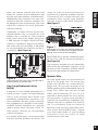
Congratulations!
Thank you for choosing a Niles loudspeaker. With proper installation and operation,
you'll enjoy years of trouble-free use.
The PSW8 wall mount subwoofer is uniquely designed to provide unobtrusive low frequency augmentation. The selectable high and low-pass filters make it suitable for use
with a wide variety of satellite speakers.
Niles manufactures the industry's most complete line of custom installation components
and accessories for audio/video systems. For a free full line catalog write: Niles, Catalog
Request, P.O. Box 160818, Miami, Florida 33116-0818
TABLE OF CONTENTS
FEATURES AND BENEFITS
2
HOW MANY SUBWOOFERS?
4
CONNECTIONS
5
IMPEDANCE
7
TREATMENT & PLACEMENT
9
INSTALLATION FUNDAMENTALS
10
INSTALLATION IN NEW CONSTRUCTION
14
INSTALLATION IN EXISTING CONSTRUCTION
15
FINAL INSTALLATION IN NEW OR EXISTING CONSTRUCTION
16
REMOVAL OF SPEAKER AND GRILLE
20
OPERATION
21
SPECIFICATIONS
22
WARRANTY REGISTRATION CARD
25
LIMITED WARRANTY
26
©2000 Niles Audio Corporation. All rights reserved. Niles, the Niles logo, Blending High Fidelity and Architecture and Systems
Integration Amplifiers are registered trademarks of Niles Audio Corporation. BumpBack and MicroSensor are trademarks of
Niles Audio Corporation. Dolby is a registered trademark of Dolby Laboratories Licensing Corporation. Decora is a registered
trademark of Leviton Manufacturing Co. Because Niles strives to continuously improve its products, Niles reserves the right to
change product specifications without notice. The technical and other information contained herein is not intended to set forth
all technical and other specifications of Niles products. Additional information can be obtained on-line at www.nilesaudio.com
or by calling Niles at 1-800-289-4434. Printed in Taiwan. 11/00 DS00278ATW
Features and Benefits
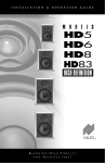
Injection Molded TCC
(Talc, Carbon and Ceramic)
Woofer with Butyl Rubber
Surround and Vented Pole Piece
The Niles PSW8 Subwoofer employs a
newly developed cone material that combines injection molded polypropylene
with talc, carbon and ceramic stiffening
agents. The result is a cone that offers
extreme stiffness and light weight for accurate, dynamic response. Additionally, the
woofer employs a vented pole piece for
increased bass linearity and a Butyl
Rubber Surround for improved damping
and clarity as well as moisture resistance.
Figure 1
Features and Benefits
Inverted Dust Cap
The inverted dust cap feature of the PSW8
actually reinforces the cone to further
increase the stiffness-to-mass ratio and
reduce distortion. In a subwoofer application, this dust cap inversion offers the additional benefit of reducing the “oil can” effect
that can cause traditional woofers to produce unwanted high frequency overtones.
Antiresonant Wave Bracing
The HD speaker’s baffle design employs
specially molded ribs that increase the
rigidity of the baffle and raise the resonant
frequency so that less “out-of-phase” cancellation takes place. Equally important,
the ribs are curved and crossed to further
shift vibration modes away from low-bass
canceling frequencies. This keeps bass
tones rich and dynamic.
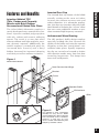
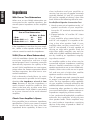
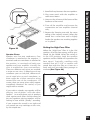
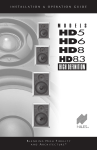
Model PSW8 Shown
New Construction Wings
Bracket
Frame
Speaker Baffle
IR Knockout
Grille
Figure 2
The PSW8 In-wall subwoofer
includes an easy access, baffle
mounted high-pass filter to prevent
over-excursion of the satellite’s
woofers. It also has an easy
access, baffle mounted low-pass
frequency selection switch.
2
Features and Benefits
High Power Handling
The PSW8 employs an exceptionally heavyduty magnet/voice-coil/spider assembly that
is capable of handling high power amplifiers (up to 150 watts).
Infinite Baffle Design
The PSW8 is designed for optimum low frequency reproduction in a traditional 2 x 4
stud wall with varying air volumes. It does
not require a special enclosure to provide
high performance.
Selectable Low-Pass Filter
Installers can select to roll off the high frequencies from the PSW8 at 12dB per octave
at either 100Hz or 140Hz. This selection is
accomplished via baffle-mounted controls
that are accessible even after the subwoofer
has been installed.
Selectable High-Pass Filter
Installers can also select whether or not to filter the low frequencies from the satellite
speakers at a fixed frequency of 120Hz. Like
the low-pass filter, this selection is accessed
via baffle mounted controls.
Moisture Resistant Construction
All components of the PSW8 are moisture
resistant. The aluminum grille is rustproof.
This makes the subwoofer ideal for moist
environments which would cause some
brands of speakers to discolor. However,
the PSW8 is not waterproof and direct
contact with water should be avoided.
Low Diffraction, MicroPerf™
Aluminum Grilles
HD speakers include aluminum grilles.
The painted aluminum grille has hundreds
of precisely sized perforations, creating an
acoustically transparent grille.
No-Strip Speaker Terminals
The PSW8 is equipped with both left and right
speaker level input terminals to accommodate
a stereo amplifier driving a single subwoofer.
3
Output terminals are also provided to utilize
the switchable low-pass filter and provide for
convenient wiring to the satellite speakers. All
terminals are Niles patented non-strip design,
which greatly simplifies installation.
Easy Retrofit Installation in your
Existing Home
Designed for ease of installation, the Niles
mounting system makes retrofit installations
simple and fast. A supplied template assures
fast and accurate hole cutting. The bracket
slips behind the drywall and the screws
secure the bracket to the frame, sandwiching the drywall between them. The speaker
baffle attaches to the frame, and the grille
mounts over the speaker.
Snap-in Baffle Assembly
This proprietary Niles design enables
installers to attach Niles loudspeaker
assemblies to previously installed frames
without additional hardware or tools. Niles'
Snap-in design makes it easy to upgrade
Niles' speakers after installation without the
hassles associated with removal and reinstallation of traditional designs. Snap-in
baffles make installation of Niles speakers
easier and faster than other in-wall brands.
Three Stage Installation System for
Remodels or New Construction
You install only the parts you need for a
particular stage of construction. When the
framing and wiring are finished, you
install the bracket. After the drywall is up,
but before the painter begins to paint, you
install the frame and provide the rustproof
aluminum grilles to the painter so that
they can be painted to match the surroundings. Only when construction is
completely finished do you put the valuable speaker in the wall. You don’t have
to mask or prep the speaker for painting,
and worries about theft during the final
phases of construction are never an issue!
For most applications a single PSW8’s is
appropriate. However, in large rooms, high
performance listening rooms or in home
theaters, an array of two or more PSW8s
will deliver astounding results. Unlike
other subwoofer systems, a Niles
Subwoofer Array is concealed. Consider
the distance between the subwoofer(s) and
the listener, the size of the amplifier, and
the desired quality and volume of sound
when deciding how many PSW8s to install
in your home.
Decibels and Power
65dB
Conversation at three feet.
75dB
Sewing Machine at three feet.
85dB
Vacuum Cleaner at 10 feet.
95dB
Subway Train entering a station
at 20 feet.
3dB
The smallest difference in volume
the human ear can easily detect.
10dB
Perceived as twice as much loudness if it is an increase (half as
much if it is a decrease).
Any speaker requires twice as much
amplifier power to increase 3dB and ten
times as much power to increase 10dB.
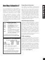
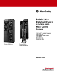
Comparison of 1, 2 or 4 Subwoofers
16’ x 18’ x 8’ Room @ 12’
25 Watts 100 Watts
1 Sub
2 Subs
VLSA of 4 Subs
95dB
100dB
103dB
101dB
106dB
109dB
2 x Watts = 3dB Increase in Volume.
2 x Subs = 3dB Increase in Volume.
2 x Subs = 1/2 the subwoofer excursion for
the same volume.
Single Stereo Subwoofer
One PSW8 can produce the bass sound
from both the left and the right channels
because of its unique dual voice coil
design. One voice coil powers the left channel and the other powers the right channel.
A stereo crossover divides the signal and filters it according to the settings of the switches on the front panel. A single stereo subwoofer is compatible with any 4 ohm stable
amplifier. Eight ohm stable amplifiers may
be used with a Niles IM volume control (see
Impedance section on Page 7)
How Many Subwoofers?
How Many Subwoofers?
Dual Subwoofer Systems
Using two PSW8 subwoofers in a system
raises the maximum attainable volume of
the system by 3dB. Additionally, at lower
volumes, excursion — and therefore distortion levels — are reduced. In a large room,
or a home theater system, the effect on
bass quality is extremely desirable.
Another 2dB increase is possible if the
voice coils of each are PSW8 paralleled.
This requires a multi-channel amplifier or
an amplifier capable of driving the 2 to 2.6
ohm load of the overall system.
VLSA Installations
A Very Large Subwoofer Array (VLSA)
installation lowers the amount of excursion required to achieve a high sound
pressure level. Lowering excursion dramatically improves the quality of the
sound. VLSA installations are most appropriate when the listener appreciates detail
and bass extension, but must have a concealed installation. A VLSA of four subwoofers must have a multi-channel amplifier with one channel assigned to each
subwoofer. (See Figure 7).
If you double the distance from the subwoofer to the primary listening position
you decrease the volume by 4 to 6dB.
4
Connections
Connections
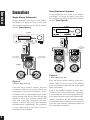
Dual Subwoofer Systems
Single Stereo Subwoofer
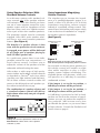
A four conductor wire (Left+, Left-, Right+
and Right-) 16 gauge or larger is run from
the amplifier location to the local volume
control. (See Figure 4).
A four conductor wire (Left+, Left-, Right+
and Right-) 16 gauge or larger is run from
the amplifier location to the local volume
control. (See Figure 5).
Amplifier
Amplifier
Left
Left
Right
Right
Wire to
Corresponding
Output
PSW-800 PASSIVE SUBWOOFER
WF
WF
R
OUT
C
L
SW1
LEFT
OUT
OUT
RIGHT
—
+
IN
IN
L
H
RIGHT
RIGHT
WF
C
IN
IN
LEFT
LEFT
LEFT
H
H
SW2
L
C
L
SW1
C
Niles Audio Corporation, Inc.
OUT
H
SW2
L
Niles Audio Corporation, Inc.
RIGHT
PSW-800 PASSIVE SUBWOOFER
L
—
+
WF
R
Either
Input
OK
Left and Right
Input terminals
Left and Right
Output terminals
PSW800
PSW800
Satellite Speaker
Satellite Speaker
PSW8
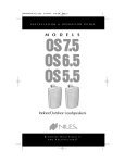
Figure 5
A Dual PSW8 Hook-Up
Satellite Speaker
Satellite Speaker
Figure 4
A Single PSW8 Hook-Up
From the local volume control, the four
conductor cable is run to the PSW8 and
connected to the Input connectors. A two
conductor wire is connected to each of the
stereo outputs and fed to the left and right
speakers. Now, the volume control will
raise and lower the volume for the subwoofer and the left and right speakers
simultaneously. Additionally, the crossover
is now connected so that the crossover
switches can be adjusted.
5
From the local volume control, a two conductor cable is run to each of the PSW8s
and connected to either the left or the right
Input connectors.
Each of the satellite speakers must be connected to the correct subwoofer. Typically,
a two conductor wire is connected from the
left channel output on the left channel subwoofer and fed to the left satellite speaker
and another two conductor wire connects
from the right channel subwoofer output to
the right channel satellite.
UT
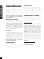
C
FRARE
IN
SENSOR
KO
D
KNO
D
FRARE
IN
KNO
U
CK O
ED SE
AR
NO
K
R
T
SO
UT
INFR
K
INFR
AR
NO
CK O
CK O
U
K
R
NO
SO
N
ED SE
CK O
U
AR
N
SO
R
NO
ED SE
K
NO
CK O
NO
AR
CK O
U
ED SE
U
R
K
INFR
INFR
SO
AR
T
T
AR
N
K
R
R
INFR
SO
SO
U
T
INFR
N
ED SE
T
N
N
KO
SENSOR
C
T
ED SE
Optionally, a jumper of wire may be connected between the L+ and the R+; and
between the L- and the R-. This connects
both voice coils of the PSW8, giving you
a 2dB increase in output. Since each subwoofer’s impedance drops from 8Ω to
4Ω, make sure your amplifier is 2Ω stable
to accommodate the satellite speaker’s
impedance. (See Figure 6).
range (or with an external electronic
crossover) by a separate amplifier channel.
Connections are straight-forward; two
conductor wires connect each amplifier
channel to each individual subwoofer.
(See Figure 7).
Connections
Now, the volume control will raise and
lower the volume for the subwoofers and
the left and right speakers simultaneously.
Additionally, the crossovers are now connected so that the crossover switches can
be adjusted to your requirements. You must
adjust the crossovers on each subwoofer
with this hook-up.
SI-1230
Figure 7
Subwoofers
Connections to a VLSA are normally made from
each PSW8 to a multi-channel amplifier like the
Niles SI-1230 twelve-channel amplifier.
Each PSW8 has a jumper installed to parallel the voice coils for maximum efficiency.
(See Figure 6).
The crossover controls on each subwoofer
affect only the subwoofer response. Level
controls on the amplifiers facilitate blending and compensation for placement.
Speaker Wire
Figure 6
Connecting the two voice coils in parallel with a
jumper (a piece of speaker wire).
Very Large Subwoofer Array
(VLSA)
Using four or more PSW8 subwoofers in a
system creates a system of unprecedented
clarity, with stunning bass impact and
potentially extraordinary maximum volume capability. Because of the extremely
low impedance of a parallel VLSA system,
multiple channel amplifiers are normally
used to power them. Because of this, inwall volume controls are incompatible
with VLSA systems.
In a system of this type, it is recommended
that the satellite speakers be driven full
For most applications, we recommend you
use 16 or 18 gauge wire. For wiring runs
longer than 80 feet we recommend 14
gauge wire. The no strip terminals of the
PSW8 speakers will accommodate up to 12
gauge wire. When you run wire inside
walls, special jacketing (CL-2 or CL-3) is
required to both protect the wire and for
fire prevention. In some areas conduit is
required. For a trouble-free installation, low
voltage wire such as speaker wire must be
run in accordance with the National
Electrical Code and any applicable provisions of the local building code. Consult
your local Niles dealer or your building
contractor if you are unsure of code
requirements in your area.
6
Impedance
Impedance
With One or Two Subwoofers
When one or two PSW8 subwoofers are
connected to the satellite speakers, the
overall system impedance to the amplifier
lowers.
System Impedance in Ohms (Ω)
One or Two Subwoofers
8Ω Sats 4Ω Sats
1 Sub
4Ω
2.6Ω
2 Subs @8Ω each 4Ω
2.6Ω
2 Subs @4Ω each 2.6Ω
2Ω
If the impedance is too low for your amplifier, utilize a Niles speaker selector or IM
volume control to match the impedance.
VLSA (Four or More Subwoofers)
A VLSA installation lowers the amount of
excursion required to achieve a high
sound pressure level. Lowering excursion
dramatically improves the quality of the
sound. VLSA installations are most appropriate when the listener appreciates detail
and bass extension, but must have a concealed installation.
Each subwoofer should have its voice
coils connected in parallel for full output,
therefore the impedance of each is four
ohms. Because of this low impedance, a
multi-channel amplifier stable to four
ohms is the best way to drive more than
two subwoofers. Each PSW8 is connected
to its own channel of the multi-channel
amplifier.
Check Your Amplifier’s Specs
Every amplifier has a minimum impedance
specification. Check your owner’s manual
for the specification for four ohm low
impedance drive capability. If there is no
7
clear indication and your amplifier or
receiver has two sets of speaker terminals
(typically labeled “A” and “B”) your amplifier may be capable of driving a four ohm
load. Perform the following test to be sure:
Parallel/Serial Speaker Connection Test
1. Hook up one pair of speakers to the “A”
speaker terminals of your amplifier.
Leave the “B” terminals unconnected to
speakers.
2. Engage both the “A” and the “B”. Listen
for sound.
If your amplifier plays sound when “A”
and “B” are engaged, it is capable of driving a four ohm speaker load. If your
amplifier does not play sound when “A”
and “B” are selected, it is only capable of
driving an eight ohm speaker load. An
eight ohm stable amplifier may only be
used with a PSW8 satellite/subwoofer system by installing an impedance magnifying volume control.
An amplifier stable to four ohms may be
connected without impedance matching
devices. Parallel connections via the “A”
speaker terminals to one or two PSW8 subwoofers (If the voice coils are not in parallel) and one pair of eight ohm satellite
speakers results in a four ohm load.
The “B” speaker terminals cannot be used
to power a second pair of speakers anymore. The low impedance drive capability
of your amplifier is already utilized by the
satellite/subwoofer combination. If you are
connecting other speakers in other rooms
you must install either a speaker selector or
impedance magnifying volume controls.
A few professional/audiophile amplifiers
advertise the capability of driving two
ohm speaker loads. These amplifiers may
be used without impedance matching
devices if the rating is quoted as “RMS” or
“Continuous” power.
Using Impedance Magnifying
Volume Controls
In multi-room systems with standard volume controls any Niles speaker selector
will maintain a four ohm load if you leave
one set of room outputs unused for every
speaker system with an impedance of less
than four ohms (such as a PSW8 connected to a pair of four ohm satellite speakers).
The protection switch must be constantly
engaged. Niles HDL series speaker selectors have a rear panel constant protection
feature. (See Figure 8).
The simplest way to increase the impedance of a satellite/subwoofer system is to
install a Niles VCS-2D-IM or VCS-2S-IM
impedance magnifying volume control
instead of a standard volume control. This
control has a behind the wall jumper which
is set at the time of installation to “magnify”
the speaker system’s impedance.
(See Figure 9).
The benefit of a speaker selector is that
even with the protection circuit constantly engaged, more power will be delivered
to any single pair of speakers playing by
itself (all other speakers off).
In a multi-room system there is one indispensible control for true convenience—a
local volume control. It allows you to
adjust the volume of the speakers and the
subwoofer without leaving the room.
Niles makes a wide range of high performance indoor and outdoor volume controls
in Standard or Decora® style face plates
(just like your light switches and dimmers).
All of these volume controls enable full
power to be delivered to each speaker system when turned all the way up.
The combination of a speaker selector and
a standard volume control will deliver
high volume when only one pair of speakers is playing.
MAGNIFICA TION
FACTOR
16x
8x
4x
2x
JP1 (LEFT)
Impedance
Using Speaker Selectors With
Standard Volume Controls
MAGNIFICA TION
FACTOR
➟
16x
8x
4x
2x
(RIGHT) JP2
Figure 9
Setting the jumper on the Niles VCS-2D-IM or
VCS-2S-IM Impedance Magnifying Volume Control
For example: In the two times position, an
IM volume control will enable an eight
ohm stable amplifier to play a 4 ohm
speaker system without overheating. The
available power will decrease, which you
will perceive as a 3dB drop in maximum
undistorted volume.
If the jumper is set to the 4x position, a
6dB drop in volume will be perceived.
If the jumper is set to the 8x position, a
9dB drop in volume will be perceived.
A 10dB drop is perceived as half as loud,
so there are limits to the amount of magnification you can use unless the amplifier is
very powerful (3dB increase every time
you double the power) or you never listen
at high volumes. Consult the Decibels and
Power chart on page 4.
Figure 8
Setting the constant protection switch on the
Rear Panel of a Niles HDL series speaker
selection system.
8
Treatment & Placement
Treatment & Placement
Typically, sheetrock encloses the subwoofer in most installations. Sheetrock has
a fairly loud resonant “twang” compared
to the rigid non-resonant enclosures of
most floor standing subwoofers. None of
the following modifications are absolutely
necessary, however any one or combination of them will improve the performance
of the subwoofer.
Minimum Enclosure Size
The PSW8 will produce magnificent
results if the wall cavity behind the
woofer is a minimum of 1900 cubic inches. If the wall studs center measure 4”
deep (2x4) and are spaced 14-1/4” apart
(16” spacing) you would want the length
of the air cavity to be a minimum of 331/3”. A larger cavity is fine.
Purchase some subwoofer damping material from a car stereo store (there are various
brands available, e.g. Dynamat™). Apply
the damping material to the back of the
wall behind the PSW8 and to the
sheetrock surrounding the wall beside the
subwoofer.
Speaker Placement Techniques
Although the PSW8 has extensive ability to
compensate for unusual placements with its
crossover switches; placement is still the
primary tool for satisfying your particular
listening needs.
Maximizing Output
Insulation
The Boundary Effect – Placing your subwoofer near the floor or in a corner will
increase the volume of bass sound produced by the subwoofer! This is called the
boundary effect. Generally, you can
expect a 3dB increase in sound pressure
level by harnessing the boundary effect.
Lay a batten of fiberglass insulation (e.g. R-19
un-batted insulation) behind of the speaker.
If you have more than one subwoofer in the
room, place the same amount of insulation
behind each subwoofer. If your enclosure is
smaller than the recommended 1900 cubic
inches, try packing more insulation into the
space behind the speaker. This effectively
increases the enclosure size.
Proximity – Place the subwoofer as close
as possible to the primary listening position. Sound dissipates indoors at approximately 4dB to 6dB for each time you double the distance from the subwoofer to the
listener. Therefore you can expect a 4dB to
6dB increase in output every time you
halve the distance from the subwoofer to
the listener.
Enclosure Bracing
Insert small pieces of 1x2 or 1x1 scrap
wood as wedges between the front and
back panels of sheetrock if possible. Do
not use too long of a piece as you could
create a bulge in the wall surface.
9
Enclosure Lining
Improving the Stereo Image
Place the subwoofer(s) as close as possible
to the satellite speakers.
Introduction
If you have doubts about whether you are
capable of installing an in-wall speaker,
consult a Niles dealer or professional
installer. They have special tools, techniques, and experience to make the impossible possible. The installer can provide you
with an estimate before any work is done.
Running the Speaker Wire in
New Construction
Plan to schedule the speaker wiring after
the electrical wiring is finished. That way
you can avoid wire routes which could
potentially induce hum over the speaker
wire. The basic rules are:
• Never run speaker wire through the
same hole as an electrical cable.
• Never run speaker wire into the same
J-box as electrical cable.
• Avoid running the speaker wire beside the
electrical cable. Keep it at least three or four
feet away from any electrical power cable.
Side-by-side wiring is unavoidable in particular spots in every house, just move the
speaker wire route away as soon as possible.
Figure 10
If construction forces a side by side run for
more than ten feet, install metal conduit or
shielded speaker wire. Low-voltage wires
such as doorbells, intercoms, telephone,
security, or television cannot cause interference or hum on your speaker wires, so you
can safely run all of them at the same time,
through the same holes, side-by-side.
Before you drill any holes, mount p-rings
or open backed J-boxes where the volume controls and stereo equipment will
be. If you are using the optional 800 New
Construction Bracket kit - (FG00321)
attach the wings and install them as
instructed on pg.14, Installation in New
Construction. (See Figure 15 and 16).
Installation Fundamentals
Installation Fundamentals
Safety First!
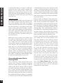
Wear gloves, safety goggles and head protection when drilling. Avoid nails, they
ruin bits and they can cause injury.
Drilling
Use a bit that is large enough for the wires
you plan to run. An auger bit is the preferred bit for rough-in wiring. It will actually pull itself through the wood, so that the
drill motor, not you, does most of the
work. You will be drilling a lot of holes, so
this is important.
Always drill the holes in the center of the
stud. If you have to notch the stud or drill
the hole closer than one inch from the edge
of the stud, protect the wire with a nail
plate (See Figure 10).
When drilling holes in ceiling joists drill in
the center of the joists and try to locate the
hole near the end of the joist. DO NOT
drill through a “gluelam” or any load bearing beam without the direction of your
contractor.
Try to line the holes up perfectly, because it
makes pulling the wire much easier.
10
Installation Fundamentals
A good technique is to snap a chalk line
across the face of the studs or against the
bottom of the ceiling joists. Then work
backward so that you can always see the
holes you have already drilled. Paying careful attention to this will save you a lot of
time later on!
is the skeleton; two-by-four wood or metal
“studs” running vertically from the floor to
the ceiling in walls and two-by-six or larger
“joists” running horizontally in the ceilings
and floors. In between the studs and the
joists is the space for the wiring and plumbing of your home.
Pulling the Cable
Pull the cable in sections (from the stereo to
the volume control, from the volume control to the speaker). Start with the longest
sections and use left over wire to complete
the short sections. If you plan to pull many
rooms at the same time through a central
route, walk off the distance to each destination, add a generous fudge factor for turns
and other obstacles, then cut off each section so that you have a bundle of wires you
can pull at once.
Exterior walls are different. They must insulate the house from the heat and cold outside, so they are stuffed with insulation. The
national building code requires that the hollow wall space in exterior walls be broken
by a horizontal stud placed between the
vertical studs. This “fire blocking” makes it
very difficult to retrofit long lengths of wire.
In some areas of the country the exterior
walls are constructed of solid masonry, and
have no hollow space for speaker wires.
Whenever you run the wire further than
four and one half feet from a hole in a stud
or joist (open attic space, going up walls,
etc.), fasten the wire to the joists or studs
using cable clamps or appropriately sized
wire staples. The wire should not have
large sags in it, nor should it be too tight.
Try to protect the wire from being stepped
on in attics or other unfinished crawl
spaces. There are guard strips, raceways
and conduits which can be used to protect
the cable. Consult the local building code
for special requirements in your area.
Concealing Speaker Wire in
Existing Walls
This is actually a fairly simple task if you
restrict your choice of speaker locations
and wire routes to the ceilings or interior
walls of your home. Interior walls in almost
all North American residences are hollow,
so it is easy to flush mount speakers into
them and route new speaker cable around
the house. What you see when you look at
the painted wall board, plaster, or paneling
is only the skin of the wall. Behind the skin
11
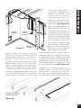
Start by examining all the possible routes
you might take to run the speaker wire
from the speaker to the volume control
and back to the stereo. Use a stud sensor
or other device to locate the internal
structure of the wall. You want to avoid
all studs or joists. A typical route would
be: from the speaker location up the
inside of the wall to a new hole drilled
into the top “plate” (horizontal two-byfour at the top of the inside of the wall),
into the attic crawl space, then down to
the volume control location through
another top plate, back up to the attic,
across the attic, and finally down another plate to the wall behind the stereo system itself (See Figure 11). The other
very common route is through the bottom plate of the wall into an unfinished
basement or crawl space.
Speaker
Location
Volume
Control
Location
Figure 11
Stereo
Location
Identify where all of your electrical,
phone, and TV wiring is likely to be and
plan to route around it all. You can accidentally induce 60 Hz hum on your
speakers if you run your speaker wire right
beside electrical wire for more than a few
feet. Try to keep speaker wire running parallel to power cables at least 3 feet away.
To find exactly where an electrical cable is
routed, try inspecting the inside of the wall
by turning off the breaker for a particular
power outlet or switch, removing the
When you don’t have access
above or below the wall, try
to estimate the existing wire
and pipe locations from the
positions of electrical outlets
and plumbed fixtures on both
sides of the wall. Take a look
at the outside of your house
too, sometimes conduit, vents
or drain pipe will be visible
that give useful information.
Choose the route with the
fewest potential obstacles.
Installation Fundamentals
cover plate and switch or
receptacle, and shining a
penlight into the wall. If you
have access to an attic or
basement space you can
quickly see which part of the
wall space the wire is free of
obstructions (See Figure 12).
If your house is built on a slab or you are
wiring between two finished floors, look
for baseboards which could be removed
and replaced with the wire behind them.
Doorjambs can be removed and often
have enough space for speaker wire all
the way around the door (See Figure 13).
Sometimes, an under-the-carpet run is
possible (there are special flat speaker
wires made for under-the-rug wire runs).
As a last resort, heating and air conditioning vents can be used as wire raceways for
Unobstructed space
for speaker wiring
Figure 12
12
Installation Fundamentals
plenum rated wire (check your local
building codes, some municipalities
require conduit).
In traditional wood stud/drywall construction you can cut the hole for the speaker
and utilize the large hole to auger holes
across, up or down the wall for as far as
your drill bit will take you. If you have
matching paint and take reasonable care in
patching you can cut a hatch in the drywall at each stud, run your wire, and patch
and touch-up the wall (See Figure 14).
When you are dealing with the unknown
because of the structure of your home, or
with difficult to patch wall materials like
plaster, lath and plaster, faux finishes,
wallpaper etc., be patient. A careful study
of the potential problems before you start
the job will pay off.
Figure 14
13
Figure 13
Stage One: Before Drywall is Hung
Insulating the Wall Cavity.
If feasible, fill the wall cavity with insulation
at this point.
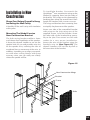
Mounting The Model 8 series
New Construction Bracket
The hole saving bracket enables a faster
and cleaner final installation of the speaker.
It forces the drywall installer to cut out the
speaker hole for you and provides wire ties
for the speaker wire, reducing the risks of
accidental loss or movement of the wire. In
addition, it enables you to align your speakers with other ceiling fixtures with great
accuracy since you can really see exactly
where the speaker will be.
To install the bracket, first attach the
QuickSnap™ new construction wings to the
bracket by snapping them into the sides of
the bracket. The wings can be shortened by
breaking them along the scored lines if their
length will interfere with a corner or eaves.
The wings and brackets have centering lines
to simplify the placement of the speaker.
Screw one side of the assembled bracket
with wings to the joist using one of the
supplied screws. Level the bracket. Screw
the other side of the bracket/wing assembly to the joist. Two screws on each side
makes for a very secure installation.
Secure the wire to the bracket using the
bracket’s wire tie (See Figure 15). The
drywall installers will cut the drywall to
the exact size of the bracket.
Installation in New Construction
Installation in New
Construction
Figure 15
New Construction Wings
Bracket
Frame
Grille
14
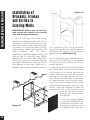
Installation In Existing Construction
Installation of
Brackets, Frames
and Grilles in
Existing Walls
IMPORTANT: Before you cut into any
wall, review the sections on running
wire and speaker placement.
1. Drill a 1/8” pilot hole just barely
through the wallboard or dry wall (1/2” to
5/8” deep in most homes) about an inch
below the center of your proposed speaker location (an inch to the side if you are
mounting the speaker horizontally). BE
VERY CAREFUL NOT TO DRILL
THROUGH EXISTING WIRES, PIPES, OR
STRUCTURE. IF YOU FEEL ANY EXTRA
RESISTANCE AS YOU ARE DRILLING,
STOP. Cut a piece of coat hanger equal to
the width of the bracket. Bend the wire in
half creating a right angle. Poke the “Lshaped” wire into the pilot hole and turn it
Figure 17
15
Figure 16
in a complete circle. If it turns freely,
repeat the procedure from a hole about an
inch above the center of your proposed
speaker location (See Figure 16).
If the wires movement is obstructed by a
pipe or cable, fill the hole (s) with spackle
or other patching compound and try
another location.
2. When determining the final location of
the cutout keep in mind that the frame
and bracket will extend beyond the
cutout. Make sure that you do not place
the edge of the cutout directly next to a
stud. Locate the studs using a stud sensor
or hand-knocking. Once you have determined the correct position for the cutout,
hold the supplied template up to the wall
surface. Level the template in either the
horizontal or the vertical position and
mark the wall with a pencil.
Drill the four corners with a
1/4” drill bit.
3. If you are cutting a painted
or wall papered drywall use
a sheetrock or keyhole saw.
Cut the hole with the saw at
a 45 degree angle. That way,
4. If you are cutting into lath and plaster
walls, use masking tape to outline your
penciled marks, drill the four corners with
a 1/4” bit and use a razor to score the
plaster down to the lath beneath. Then use
a chisel to remove all of the plaster within
the taped outline. Finally, insert a metal
cutting blade into a sabre saw and very
slowly and carefully saw the lath. Sawing
the lath can easily vibrate plaster off the
wall. If you have the patience, use a pair
of tin snips to slowly nip away at the lath
instead. There is no risk with this method,
it is just time consuming.
5. Fill the wall cavity with insulation at
this point. Remember to use equal
amounts of insulation for each speaker.
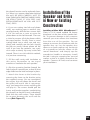
Installation of the
Speaker and Grille
in New or Existing
Construction
Installing a Niles MS-1 MicroSensor™
There is a 1/2" round molded "IR Sensor
Knockout" on the face of the speaker baffle. To prevent damage to the crossover
network you must remove the knockout
from the rear of the speaker. Do not
attempt to remove the knockout with the
speaker face up. Lay the speaker face
down on a clean carpet or rug. Put the tip
of a screwdriver into the center of the
round "knockout" and sharply tap the
screwdriver handle as necessary. Install
the MS-1 using its mounting hex nut and
washer so that it is tightly secured to the
speaker. Connect all wires and continue
your installation.
Final Installation In New Or Existing Construction
the drywall section can be replaced cleanly if there is an unseen obstruction behind
the wall. BE VERY CAREFUL NOT TO
SAW THROUGH EXISTING WIRES, PIPES,
OR STRUCTURE. IF YOU FEEL ANY
EXTRA RESISTANCE AS YOU ARE CUTTING, STOP.
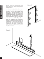
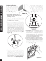
6. Slip the mounting bracket through the
hole and pull it toward you so that its front
edge slides into the hole and stops in place.
7. Attach the frame to the bracket by
screwing the frame to the bracket using
the supplied screws. Do not overtighten
the screws, this will distort the frame and
the grilles will not fit (this is not permanent, just loosen the screws and the grille
will pop in). The screws should pull the
frame and bracket together (sandwiching
the drywall) so that the frame is absolutely
flush with the wall surface. There should
be no gaps between the wall and the
frame (See Figure 17).
16
Final Installation In New Or Existing Construction
Installing the Speaker
If the grille is already
installed, remove it by
using a bent paper clip or
the tip of a corkscrew and
pulling it away from the
frame (See Figure 18).
5. Place the speaker baffle in
the frame by installing the
legs in the corresponding
holes in the frame and
tilting the speaker forward
until the snaps engage
(See Figure 21).
Figure 18
1. Separate the speaker wire so
that at least two inches of each
conductor are free.
2. Open the no-strip terminal by applying
pressure to the red and black levers until
an audible “click” is heard.
3. Insert one unstripped wire fully into the
black and one into the red terminal. Pay
attention to the markings on the wire.
Each speaker must be connected to the
amplifier in the same way. Squeeze the
red and black levers until they click signifying that they have locked into the
wire. Check to make sure that the knife
assembly inside the no strip connector
has properly pierced the wire (See
Figure 19).
Figure 20
6. Important: When installing the speakers in the ceiling, or if the installation is
located within an earthquake zone, it is
recommended that you utilize the
enclosed self tapping sheetmetal screws
to secure the baffle to the frame.
a. Locate the dimples on the front baffle.
b. Place the self-tapping sheet metal
screw in the dimple and turn it with a
screw driver until it cuts through the
baffle and anchors securely in the
frame (See Figure 22).
Figure 19
4. Insert the no strip terminal into the corresponding socket on the rear of the
speaker. Push it down until it locks in
place. The terminal will only fit in the
socket in one direction. If the terminal
does not properly seat, reverse the terminal 180˚ and re insert (See Figure 20).
Figure 21
17
2. Play some music with the amplifier or
radio set to Mono.
3. Listen to the richness of the bass and the
loudness of the sound.
4. Turn off the amplifier and reverse the
connections on one amplifier channel
only.
5. Repeat the listening test with the same
setting of the volume control. When the
sound has a richer bass and is slightly
louder the speakers are working together
or “in-phase”.
Figure 22
Speaker Phase
Speaker wire has two conductors. One
conductor is attached to the negative (-)
terminals and one conductor is attached to
the positive (+) terminals of both your
speaker and your amplifier. Usually, the
wire is marked for your convenience.
There are different ways wires are marked:
a stripe on one wire, a ribbed area of one
conductor you can only feel, different colors of metal wire on each conductor, or
there might be a fabric strand or string
wound into one of the conductors. Of
course, there are some wires which appear
completely identical. Be careful, or you
might make a mistake.
If you make a mistake, one speaker will be
playing “out-of-phase” with the other
speaker. An out-of-phase pair of speakers
work against each other and the sound of
the two speakers playing together will be
lacking in bass and be “phasey” sounding.
If you suspect the sound is not right and
you cannot see any markings on the wire,
try this simple test:
Setting the High-Pass Filter
When the “High Pass” filter is in the ON
position, all of the bass energy will be produced via the PSW8. When the switch is
in the OFF position, both the satellite
speakers and the PSW8 will reproduce the
bass signal. Typically, satellites with
woofers that are 5-1/4” or smaller will
sound best with the filter on. Listen to a
loud and well recorded bass passage to
evaluate (See Figure 23).
Final Installation In New Or Existing Construction
1. Stand half way between the two speakers.
Figure 23
18
Final Installation In New Or Existing Construction
Setting the Subwoofer
Low-Pass Filter
With the “Low Pass” switch in the 100Hz
position, the PSW8 will only reproduce
bass below one hundred cycles. When the
switch is in the 140Hz position, the PSW8
will reproduce bass below 140 cycles.
Depending on the size of the room, the
type of satellite speaker and the subwoofer
position, you will prefer one setting to the
other. Listen to a loud and well recorded
bass passage to evaluate (See Figure 23).
Install the grille into the speaker. The grilles
should fit snugly. If you have difficulty fitting
them in, try loosening the screws used to
secure the frame to the bracket slightly
(excessive tightening can distort the shape of
the frame holding the grille in place).
Painting the Speakers
All models may be painted. The plastic will
readily accept most paints.
The subwoofers must be masked prior to
painting them. The inside rectangular portion of the hole template can be used as a
paint mask. Remove the outside portion of
the template by gently pulling along the
perforation. Affix the mask to the front of
the speaker by friction-fitting the mask into
the bezel.
The grilles should be painted before they
are installed. For all models, the best
results will be obtained by using a spray
gun or airless sprayer, thinning the paint
(prevents clogging of grille holes), and by
applying several light coats instead of one
heavy one.
19
Speaker/Subwoofer Phase
Speaker wire has two conductors. One
conductor is attached to the negative (–)
terminals and one conductor is attached to
the positive (+) terminals of both your
speaker and your amplifier. Usually, the
wire is marked for your convenience.
There are different ways wires are marked:
a stripe on one wire, a ribbed area of one
conductor you can only feel, different colors of metal wire on each conductor, or
there might be a fabric strand or string
wound into one of the conductors. Of
course, there are some wires which appear
completely identical. Be careful, or you
might make a mistake.
If you make a mistake, there are three possibilities:
1) Subwoofer Input Phase Reversal
The Left Input of the subwoofer is out of
phase with the Right Input. If this is the
case, you will hear almost no output out of
the subwoofer when playing a loud bass
passage. Try reversing one of the subwoofer
inputs. If the sound gets a great deal louder,
that was the problem. If bass sound was
reduced, return the connections to their
original state.
2) Subwoofer /Satellite Relative Phasing
An acoustically out-of-phase sat/sub combination works against each other and the
sound of the overall system will be lacking
in bass. This might be because of the position of the subwoofer rather than an error in
wiring. Try reversing the phase of both the
left and the right outputs of the subwoofer.
Make sure you evaluate (listen) from the
primary listening position.
5. Repeat the listening test with the same
setting of the volume control. When
the sound has a richer bass, is slightly
louder and the vocal image is
“focused” the satellites are working
together or “in-phase”.
180
4. Turn off the amplifier and reverse one of
the connections on the subwoofer.
w 1w 80 0-B
w
.n 0-28 U
ile
Ysa 9- H
ud 44 IF
io 34 I
.c
om
3. Listen to the apparent placement of the
vocals.
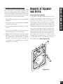
Utilizing 2 small screwdrivers or needle
nose pliers, release the side snaps that
hold the speaker to the frame. Insert the
screwdriver into the hole in the snap and
exert force straight inward (towards the
woofer) until the snap releases. Follow the
same process with the snaps at the top.
Once the snap releases, the speaker can
be tilted away from the frame to be
removed. Do not attempt to use the frame
for leverage, as this may damage the surface of the frame (See Figure 24).
180
2. Play some vocal music with the amplifier
or radio set to Mono.
Removing The Speaker
If the grille is already installed, remove it by
using a bent paper clip or the tip of a
corkscrew and pulling it away from the frame.
w 1w 80 0-B
w
.n 0-28 U
ile
Ysa 9- H
ud 44 IF
io 34 I
.c
om
1. Stand half way between the two satellite
speakers.
Removal of Speaker
and Grille
Removal of Speaker and Grille
3) Satellite Left-Right Phase Reversal
If the right satellite is reversed in phase from
the connections on the left satellite, you
will hear reduced bass and a “phasey” diffused vocal image. If you suspect the sound
is not right and you cannot see any markings on the wire, try this simple test:
1-
ww
I
HIF
Y- 34 m
BU 44 co
0- 9- o.
80 0-28 di
1- 80 esau
nil
w.
1- nil
w.
ww
I
HIF
Y- 34 m
BU 44 co
0- 9- o.
80 0-28 di
1- 80 esau
Figure 24
20
Operation
Operation
Congratulations
A concealed PSW8 subwoofer installation
frees you to use your tone controls, play the
system loudly and enjoy deep extended
bass, even if your satellite speakers are
small. When used with satellite speakers
that have substantial bass of their own, the
PSW8 tightens the deep tones and augments the bass musically.
Listening at Higher Volumes
It requires more power to achieve a reasonable volume of sound in a large room than
it does in a small room. It is possible (even
if you are not a teenager) to turn the volume so high that the amplifier runs out of
power. This creates “clipping” distortion. If
you are using an extremely powerful amplifier it may be possible to hear clicking or
buzzing sounds from the subwoofer as it
tries to reproduce too loud a sound. If you
hear these sounds turn the volume down.
More typically you will hear clipping distortion through your satellite speakers.
Clipping distortion makes treble sound very
harsh and unmusical. When you hear harsh
sounding treble from any good speaker,
turn the volume down immediately! Those
harsh sounds are masking some much
more powerful ultra-high-frequency sound
spikes which will quickly damage any fine
loudspeaker. You are much less likely to
damage a speaker with a large amplifier
because it will be very loud indeed before
it produces any clipping distortion.
Cleaning
You can clean the speaker with a dampened soft cloth or paper towel. If the speaker is mounted high up on the wall, use a
broom to gently brush it off.
21
Model PSW8
Driver Complement
8" injection-molded TCC (talc, carbon and
ceramic-filled polypropylene) woofer, custom
debris screens, high BL magnet structure with
vented pole piece
Specifications
Specifications
Design Principle
Infinite baffle for large and varying air volumes
Recommended Amplifier Power
Ten to one hundred fifty watts per channel
Impedance
8 Ohm - single subwoofer in stereo
4 Ohm - single subwoofer with voice coils
paralleled for full monophonic output
Frequency Response
35 Hz to 140 Hz, plus or minus 3dB
(on axis)
Sensitivity
89 decibels for 2.83 volts of pink noise,
measured at 1 meter on axis
Overall Exterior Frame Dimensions
10-3/16” x 14-1/4”
Depth Behind Wall
3-3/4” (assumes 1/2” drywall)
Wall Cut-Out Dimensions
9-1/8” x 13-1/8”
Wiring Requirements
We recommend 16 to 18 gauge for up to
80 feet, 14 gauge for up to two hundred
feet. Connectors accommodate 12 to 18
gauge wire.
22
23
PLEASE FILL OUT THE
WARRANTY REGISTRATION
CARD ON THE REVERSE SIDE,
DETACH, AND MAIL TO:
DETACH HERE
Niles Audio Corporation
Warranty Registration Dept.
P.O. Box 160818
Miami, Florida 33116-0818
®
WA R R A N T Y R E G I S T R AT I O N C A R D
Model Purchased___________________________________
_________________________________________________
Serial Number____________________________________________________________________________________
Dealer Name and Location________________________________________________________________________
__________________________________________________________________________________________________
❑ Dr.
❑ Miss
❑ Mr.
❑ Mrs.
❑ Ms.
Name______
______________________________________________________________________________________
Address_________________________________________________________________________________________
__________________________________________________________________________________________________
City_________________________________________________________State______
__________Zip______________
Telephone (___________)___________________________________________________________________________
Please take a moment to fill out our warranty registration card. The information helps us to
get to know you better and develop the products you want
Age:
❏ Under 25
❏ 25-34
❏ 35-44
❏ 45-54
❏ 55 & over
Income:
❏ Under $24,999
❏ $25,000-$34,999
❏ $35,000-$44,999
❏ $45,000-$59,999
❏ $60,000-$74,999
❏ $75,000-$99,999
❏ Over $99,999
Occupation:
❏ Arts/Entertainment
❏ Business Owner
❏ Engineer
❏ Finance/Accounting
❏ General Office
❏ Management
❏ Professional
❏ Sales/Marketing
❏ Student
❏ Tradesperson
Musical tastes:
(Please check all that
apply)
❏ Alternative
❏ Classical
❏ Country
❏ Jazz
❏ New Age
❏ Popular
❏ R&B
❏ Rock
❏ Other__________
____
How did you hear
about Niles?
❏ Architect/Developer
❏ Custom Installer
❏ Direct Mail
❏ Friend/Family
❏ In-Store Display
❏ Interior Designer
❏ Magazine Ad
❏ Mail-Order Catalog
❏ Newspaper Ad
❏ Product Brochure
❏ Product Review
❏ Retail Salesperson
What magazines do
you read?
1. ___________________
2. ___________________
3. ___________________
Who will install the
product?
❏ Custom Installer
❏ Electrician
❏ Friend
❏ Myself
Which factor(s) influenced the purchase of
your Niles product?
(Please check all that
apply)
❏ Ease of Use
❏ Price/Value
❏ Product Features
❏ Quality/Durability
❏ Reputation
❏ Style/Appearance
❏ Warranty
Do you . . . ?
❏ Own a House. If yes,
how many square feet?
__________________
❏ Own a Town House/
Condominium/Co-op
❏ Rent an Apartment
❏ Rent a House
Are you interested in
receiving literature on
other Niles products?
❏ Yes
❏ No
Are there products/
capabilities that you
would like to see
introduced?
____________________
____________________
____________________
____________________
____________________
____________________
DETACH HERE AND RETURN TO: Niles Audio Corporation Warranty Registration Dept. P.O. Box 160818 Miami, Florida 33116-0818
Date Purchased (month/day/year)__________________________________________________________________
Niles Audio Corporation ("NILES") warrants its loudspeaker products to the original purchaser
to be free of manufacturing defects in material and workmanship for a period of five years
from date of purchase.
This Warranty is subject to the following additional conditions and limitations. The Warranty
is void and inapplicable if NILES deems that the product has been used or handled other than
in accordance with the instructions provided by the manufacturer, including but not limited to
damage caused by accident, mishandling, improper installation, abuse, negligence, or normal
wear and tear, or any defect caused by repair to the product by anyone other than NILES or an
authorized NILES dealer.
Limited Warranty
Limited Warranty
To obtain warranty service, take the unit to the nearest authorized NILES dealer, who will test
the product and if necessary, forward it to NILES for service. If there are no authorized NILES
dealers in your area, you must write to NILES and include your name, address, model and
serial number of your unit, along with a brief description of the problem. A factory Return
Authorization Number will be sent to you. DO NOT RETURN ANY UNIT WITHOUT FIRST
RECEIVING WRITTEN AUTHORIZATION AND SHIPPING INSTRUCTIONS FROM NILES.
If the above conditions are met, the purchaser's sole remedy shall be to return the product to
NILES, in which case NILES will repair or replace, at its sole option, the defective product
without charge for parts or labor. NILES will return a unit repaired or replaced under warranty
by shipping same by its usual shipping method from the factory (only) at its expense within the
United States of America. THERE ARE NO OTHER WARRANTIES, INCLUDING WITHOUT
LIMITATION, EITHER EXPRESS OR IMPLIED WARRANTIES OF MERCHANTABILITY OR FITNESS FOR A PARTICULAR PURPOSE, WITH RESPECT TO THE PRODUCT.
REPAIR OR REPLACEMENT AS PROVIDED UNDER THIS WARRANTY IS THE EXCLUSIVE
REMEDY OF THE CONSUMER/PURCHASER. NILES SHALL NOT BE RESPONSIBLE FOR
ANY INCIDENTAL OR CONSEQUENTIAL DAMAGES EXCEPT TO THE EXTENT PROVIDED
(OR PROHIBITED) BY APPLICABLE LAW.
Some states do not allow the exclusion or limitation of incidental or consequential damages,
so the above limitation may not apply to you. This warranty gives you specific legal rights, and
you may also have other rights which vary from state to state.
For the name of your nearest authorized NILES dealer contact:
NILES AUDIO CORPORATION
P.O. BOX 160818, Miami, Florida 33116-0818.
Please fill in your product information and retain for your records.
Model_________
___________________________________________________________________________
Serial No._____
____________________________________________________________________________
Purchase Date____
_________________________________________________________________________
26
Niles Audio Corporation
12331 S.W. 130 Street
Miami, Florida 33186
Tel: (305) 238-4373
Fax: (305) 238-0185
www.nilesaudio.com
© 2000 Niles Audio Corporation. Patents applied for and pending.
Printed in Taiwan DS00278ATW