1
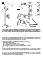
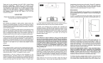
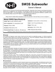
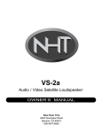
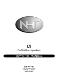
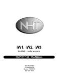
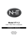
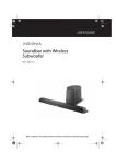
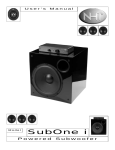
VS-1.2a Audio / Video Satellite Loudspeaker OWNER’S MANUAL Now Hear This 6400 Goodyear Road Benicia, CA 94510 800-NHT-9993 Thank you for your purchase of the NHT VS-1.2a Audio / Video Satellite Loudspeaker. Please take a few minutes to read through this Owner’s Manual prior to installing your new speaker. The information provided will help you to obtain maximum performance from your audio system. If you have questions or need assistance at any time during the installation or operation of your new speaker, please call your NHT dealer or our Toll Free Customer Hotline at: 1-800-NHT-9993 Please retain the VS-1.2a’s packaging to protect the speaker in the event that you move or transport it. VS-1.2a Specifications · System Type: 2-way acoustic suspension · Driver Complement: Two 4.5” woofers, 1” fluid-cooled soft dome tweeter, video shielded drivers · Crossover: 2.2KHz, 12dB/octave high-pass and low-pass · Response: 80Hz - 21KHz, +/- 3dB · Sensitivity: 86db (2.83V at 1M) · Impedance: 8 ohms nominal, 6.3 ohms minimum · Recommended Amplifier Power: 15W/ch minimum, 150W/ch maximum · Inputs: 5-way binding posts · Weight: 13.5 lbs. each · Dimensions: 5.5”H x 19”W x 8"D · Finish: High gloss black or white laminate Specifications are subject to change without notice, in accordance with our policy of continuously upgrading the performance of our products. Design NHT speakers are designed to deliver refined, musical sound from attractive and affordable packages. Our efforts are guided by the study of human hearing and are optimized for real-world use. Every NHT speaker undergoes rigorous testing and quality control at the factory to ensure you years of listening pleasure. The magnetically shielded VS-1.2a Audio / Video Satellite loudspeaker is designed to provide high-performance sound when used as a front, center, and surround speaker in five-channel home theater systems. The VS-1.2a employs the identical drive units as the companion VT-1.2 Audio / Video Tower loudspeaker, which may be used as front left & right speakers for a full-range, timbre-matched system. Placement The VS-1.2a is designed for use as either a center channel speaker in its horizontal orientation, or a satellite speaker in its vertical orientation. The VS-1.2a is designed for indoor use only. When installing the VS-1.2a as a center channel speaker, it should be placed directly above or below the television, as close to the screen as possible (fig.1). The VS-1.2a is magnetically shielded and will not distort the picture’s color. Ideally, the three front speakers in a home theater system should be placed at equal height, equidistant, and at ear level from the listening position. However, it is frequently not possible to install a center speaker at ear level, as the top surface of most televisions tends to be higher than ear level in the seated position. To address this problem, the VS-1.2a is supplied with an adjustable foot (fig. 2). This foot is used to angle or aim the speaker so that it radiates sound directly toward the listening position. The foot can also be used to level the VS-1.2a if the top of the TV has an uneven surface. Attach the rubber pad to the bottom of the foot to prevent it from sliding. Adjust the VS-1.2a to the desired angle, then tighten the finger screw. For best performance, place the VS-1.2a so that its baffle (front) is even with the front of your television (fig. 3). This will eliminate diffraction effects caused by sound waves bouncing off the top surface of your television. Rubber feet are included to protect both your VS-1.2a and your furniture from possible scratches. To install the feet, peel off their adhesive backings and stick them on four corners of the bottom surface, (whichever it is) of the VS-1.2a. 1 fig. 2 fig. 1 When used as front or rear satellite speakers, the VS-1.2a’s should be arranged as symmetrically as possible.The speakers should be slightly toed-in and the drivers should face the listening area without obstruction from furniture. If possible, arrange the speakers so that the distance between the listener and the center or the speaker plane is about 1.5 times the distance between the two speakers (fig. 3). This configuration puts the listener in the center of the stereo image. For 5.1-channel discrete digital surround systems, we recommend that all five speakers be placed equidistant from the listening position. For Dolby Pro-Logic® systems, it is preferable to have a more diffuse, ambient sound radiating from behind the listening position. This is accomplished by placing the rear (surround) speakers so that they fire across the room at each other (not directly toward the seating position), and by placing them 3 to 4 feet above ear level. Experimentation is the key to finding the best arrangement in your listening environment. Be patient, have fun, and remember that small changes in speaker position can sometimes have a significant effect on the sound. For example, moving the speakers nearer to a room boundary (walls, corners) will tend to increase their bass output, but may result in “boomy” or “muddy” sound. Conversely, placing the speakers farther away from room boundaries will tend to decrease their bass output, but may result in greater articulation and better imaging. fig. 3 In addition, room furnishings play an important role in absorbing and reflecting soundwaves. Midrange and high frequencies in particular will be absorbed by soft furnishings such as sofas, carpets and curtains. A large number of these soft furnishings will dull the sound, while a “live” room with few furnishings will brighten the sound. If you are willing to spend some time fine-tuning the performance of your system, you will enjoy the benefits for years to come. Speaker Stand and Shelf Mounting When used in the vertical (upright) orientation, the VS-1.2a may be placed on a rigid speaker stand. NHT offers a 26.5” stand (OneStand) which is ideally suited for the VS-1.2a. Refer to the OneStand owner’s manual for detailed installation instructions. Additionally, the VS-1.2a may be placed on a shelf or in a cabinet, however this placement may have a detrimental effect on the sound. For best results, place the speaker as far forward as possible to the front edge of the cabinet. Wall Mount Bracket Parts List: Tools you will need: 2 2 4 1 power drill with 1/8-inch bit Philips screwdriver or power driver studfinder level brackets long screws (#10 x 2” pan head) short screws (#7 x 3/4” pan head) template (included with owner’s manual) 2 Whenever an object is affixed to a wall, you must take special care to mount it securely, to prevent it from falling and causing possible injury. THE VS-1.2a MOUNTING BRACKET MUST BE ATTACHED TO STUDS, AS DRYWALL (SHEETROCK) ALONE CANNOT PROVIDE ADEQUATE SUPPORT. Make sure that the mounting bracket will not interfere with electrical wiring, plumbing, etc. IF YOU ARE UNSURE ABOUT THE INSTALLATION OF THIS MOUNTING BRACKET, CONSULT A PROFESSIONAL CONTRACTOR. Follow the mounting instructions carefully to ensure proper installation. There are two ways to mount the VS-1.2a to the wall with the supplied mounting bracket: horizontally or vertically. Before installing the bracket, determine the desired orientation of the speaker. If the VS-1.2a’s are to be mounted on the side walls and behind the listening position, it is advisable to mount them vertically, using the cabinets’ shape to aim the speakers inward toward the listening position. If the VS-1.2a’s are to be mounted on the rear wall of the room, it is advisible to mount them horizontally and high up on the wall, using the cabinets’ shape to aim the speakers downward toward the listening position. 1. Do not attach the bracket to the VS-1.2a yet! That comes later. 2. Begin by selecting the desired area on the wall where the VS-1.2a will be mounted. Using a studfinder (or the old-fashioned “knocking” method), locate one or two adjacent studs, spaced 16 inches apart. If the VS-1.2a is to be mounted vertically, both brackets are mounted to the same stud. If the VS-1.2a is to be mounted horizontally, the brackets must be mounted to two adjacent studs. 3. Using the supplied mounting template, mark the two screw locations, 16 inches apart and centered on the stud(s) - (see Fig. 4). Use the level to ensure that the screw locations are lined up precisely. 4. Drill a 1/8-inch pilot hole into the wall for each screw. Be sure that the hole passes through the drywall and into the stud. If the hole does not reach a stud, re-position the screws and pilot holes until it does. 5. Insert one long screw into each pilot hole. Screw all the way into the wall, until the screw head rests on the wall surface. 6. Place an unmounted bracket over each screw so that the screw head rests in the round section of the keyhole (Fig. 5). Don’t worry about which keyhole to use at this point. Loosen the screw 1 to 1-1/2 turns, until the bracket is able to slide down and the screw head now rests in the narrow section of the keyhole. The wall screws are now properly set. 7. Locate the four pilot holes (two per side) pre-drilled into the back of the VS-1.2a. Place one bracket above each pair of holes (Fig. 6). Take care to align the brackets carefully: Both brackets must be installed facing the same direction to ensure fig. 5 fig. 4 3 fig. 6 fig. 7 exact 16” spacing. There are three offset “keyholes,” but only one keyhole will be correct for your installation (see Fig. 7). When mounting the VS-1.2a vertically, use the middle keyhole on each bracket, and make sure that the brackets are installed so that the narrow section of each keyhole faces the direction that will be “up” once the speaker is on the wall. When mounting the VS-1.2a horizontally, use the appropriate “up”-facing keyhole on each bracket, making sure that both brackets face the same direction. 8. Using the short screws, attach the brackets to the VS-1.2a. Do not over-tighten the screws, as this may strip the pilot holes. On power screwdrivers, use the low-torque setting. Tighten the screws enough so that the bracket cannot move on the speaker. 9. Attach speaker cable to the VS-1.2a. When possible in new construction applications, run the cable inside the wall and have it come out directly behind the location of the VS-1.2a. If this is not possible, simply run the cable along the wall behind the VS-1.2a. Note: The speaker cable must be a maximum of 1/8-inches thick in order to fit between the speaker and the wall. 10. Hold up the VS-1.2a so that the brackets are aligned with the wall screws. Carefully place the brackets over the screws so that the screw heads slide into the round sections of the keyholes. Slowly move the VS-1.2a downward until the bracket has locked over the screw. Ensure that both brackets are securely mounted to their screws. If you are unable to slide the VS-1.2a brackets down onto the wall screws, check to ensure: z Nothing is obstructing the speaker z The brackets are mounted on the speaker with both facing the same direction z You are using the proper keyhole on both brackets z The wall screws are exactly 16 inches apart, centered on the studs z There is enough room between the screw head and the wall for the bracket to slide down. System Configurations The VS-1.2a is optimized for use in the latest five-channel discrete digital surround systems. Since digital surround soundtracks are mixed as five discrete channels, uniform tonality in the playback system is essential for achieving a believable “you are there” sound. The VS-1.2a satellites and VT-1.2 towers utilize identical upper range drivers, so there are two system configurations that will each provide matched timbre to all five channels: 1- Use a pair of VT-1.2 Audio / Video Towers for the front left and right speakers and three VS-1.2a’s for the center and rear speakers. Configure all low frequencies to be sent to the VT-1.2’s. Since the VT-1.2’s have built-in subwoofers, a separate subwoofer is an option and not a necessity in this system. 4 2- Use five VS-1.2a’s (front left, center and right, rear left and right) and a separate powered subwoofer (NHT SubOne or SubTwo) for the low frequency effects channel. For a no-holds-barred home theater system starting with either of the above configurations, powered subwoofers may be employed on any or all five channels to provide balanced bass and increased impact. Connections Before connecting speakers to your system, it is very important that you turn off the power to your amplifier / receiver to avoid damage to the equipment. The VS-1.2a is compatible with virtually all quality amplifiers. Proper wiring of the speaker is essential to good sound. At a minimum, 16 AWG speaker cable is recommended for runs of 10 feet or less, with 14 AWG cable used for larger runs. For specialty cable considerations, consult your local authorized NHT retailer. For best results, use equal length runs of cable for all three front speakers. Prepare your cable by stripping 1/4” to 3/8” of insulation from the ends and twisting the exposed wire strands tightly. The five-way binding posts on the back of the speaker will accept raw wire, banana plugs, or spade plugs. Tighten the binding posts by hand, as pliers can strip or break them. Be sure to wire all the speakers “in-phase.” That is, the Positive (red) terminal on the amplifier output must be connected to the corresponding Positive (red) terminal on the speaker. Likewise with the Negative (black) terminals. All speaker wires have some sort of marking along one or both conductors to help you make the correct connections. Incorrect speaker phase is indicated by weak bass and the lack of a well-defined stereo image. To minimize noise pickup, segregate cables by function. Do not run low level signal cables parallel to power cables, speaker cables, or digital cables. Also, do not run speaker cables or digital cables parallel to power cords or parallel to each other. If different types of cables are placed near each other at some place in your system, separate them by the maximum practical distance and cross them at right angles where they meet. Do not twist or tie AC power cords with speaker cables. Operation The VS-1.2a was designed to handle a wide range of listening levels, but every speaker has limits. It is important to use common sense and listen for signs of possible distress from the speakers. Underpowered amplifiers are most often the cause of speaker damage. For example, a 60-watt amplifier runs out of power when called upon to produce more than 60 watts, and the resulting distortion can damage the speaker. If you tend to listen at high voumes, more powerful amplifiers are preferable because they are less likely to run out of power. Noticeable distortion or harsh breakup is an indication that either your amplifier or your speakers are running beyond their capacity, and the volume should be decreased. If you can feel any heat emanating from the woofer or tweeter, reduce the level immediately. Speaker damage most often occurs from sustained high volume levels, not from transient sounds or brief musical peaks. Excessive boosting of bass, treble or equalizer controls can worsen the problem, and is not recommended. Maintenance Your speakers require minimal maintenance under normal use. The cabinet may be cleaned using a damp cloth or a mild, non-abrasive glass cleaner. To clean the grille, first remove it from the speaker, then brush lightly with a soft brush or use a vacuum on its lowest setting. Do not expose the speaker to direct sunlight, high temperatures, or moisture. Do not attempt to clean the actual drivers. Limited Warranty Valid Only in the U.S.A. Warranty Period For the period of 5 years for parts and 5 years for labor from date of original purchase (the warranty period) from an authorized NHT dealer, Now Hear This (NHT) warrants that if our product fails to function properly under normal use due to a manufacturing defect when installed and operated according to the owner’s manual instructions enclosed with the unit, it will be repaired or replaced with a unit of comparable value at the option of NHT without charge to you for parts or actual repair work. Parts supplied under this warranty may be new or rebuilt at the option of NHT. What’s Not Covered This warranty does not cover any product which is used in any trade or business, or in an industrial or commercial application. This warranty does not cover the cabinet or any appearance item, or any damage caused to the product resulting from: alterations, modifications not authorized in writing by NHT, accident, misuse or abuse, damage due to lightning or power surges, or being subjected to power in excess of the speaker’s published power rating. This warranty does not cover the cost of parts which would otherwise be provided without charge under this warranty, obtained from any source other than an authorized NHT service location. This warranty does not cover defects or damage caused by the use of unauthorized parts or labor or from improper maintenance. Altered, defaced or removed serial numbers void this warranty. Your Rights The liability of NHT will be limited to the purchase price of the product, and NHT will not be liable for incidental or consequential damages. NHT limits its obligations under any implied warranties under state laws to a period not exceeding the warranty period. Some states do not allow limitations on how long an implied warranty lasts, and some states do not allow the exclusion or limitation of incidental or consequential damages. The above limitations or exclusions may not apply to you. This warranty gives you specific legal rights, and you may have other rights which vary from state to state. To Obtain Service NHT has appointed a number of authorized service companies throughout the USA should your product ever require service. To receive warranty service, you will need to present your sales receipt showing place and date of original owner’s transaction. To find the name and address of the nearest authorized NHT service location, call 800-NHT9993 or write: NHT, 6400 Goodyear Road, Benicia, CA 94510. Keep this warranty with your sales receipt. Record date and place of purchase for future reference. 5