1
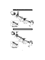
INSTALLATION & OPERATING INSTRUCTIONS
WARNING − RISK OF ELECTRIC SHOCK. CONNECT
ONLY TO A CIRCUIT
PROTECTED BY A GROUND-FAULT CIRCUIT-INTERRUPTER. THE UNIT SHOULD BE INSTALLED BY
A QUALIFIED SERVICE REPRESENTATIVE.
ALL ELECTRICAL WIRING OF THE MOTOR
INSTALLATION MUST BE DONE BY A QUALIFIED ELECTRICIAN IN ACCORDANCE WITH
APPLICABLE ELECTRICAL CODES. GROUNDING IS REQUIRED. BEFORE WORKING ON ANY
MOTOR, BE CERTAIN THAT THE SOURCE OF ELECTRICAL POWER IS OFF AT THE MAIN JUNCTION
BOX.
BONDING WIRE − UPON INSTALLATION OF THE PUMP, THE MOTOR MUST BE BONDED
2
WITH (NO SMALLER THAN) A NO.8 AWG (8.4MM ) SOLID COPPER CONDUCTOR PER
NATIONAL ELECTRIC CODE. THE CONNECTION SHOULD BE FROM THE ACCESSIBLE WIRE
CONNECTOR ON THE MOTOR TO ALL METAL PARTS OF THE SWIMMING POOL, SPA, OR HOT
TUB STRUCTURE AND TO ALL ELECTRICAL EQUIPMENT, METAL CONDUIT AND METAL
PIPING WITHIN 5 FEET (1.5M) OF THE INSIDE WALLS OF THE SWIMMING POOL, SPA, OR HOT
TUB, WHEN THE MOTOR IS INSTALLED WITHIN 5 FEET OF THE INSIDE WALLS OF THE
SWIMMING POOL, SPA, OR HOT TUB.
NOTE: FOR ELECTRICAL CONNECTIONS, SEE WIRING DIAGRAM ON MOTOR RATING PLATE.
GENERAL
Your AQUA-FLO pump has been quality built and engineered to give maximum
efficiency under normal water pumping conditions. Consult the manufacturer for
any other applications.
LOCATION OF PUMP
For best pump performance, locate the system as close to the water source as
possible. Provide adequate access around the pump for inspection and
maintenance.
MODELS LESS TRAP
This pump was designed for below water level (flooded suction) applications.
Make sure the pump is installed at a level that will allow the pump casing (volute)
to be completely filled with water.
Two quick disconnect compression fittings are included with your pump for ease
of installation and maintenance. Make sure the fittings are correctly aligned with
pump connections to allow the o-ring to make the proper seal. Hand tighten
only. Do not use a wrench to tighten fittings.
MODELS WITH TRAP
Avoid excessive tightening of pipe or fittings in any areas where threaded
connections are used.
For NPT threaded connections, use Quick-Seal Teflon Thread Sealing
Compound, Plasto-Joint Stick or any other sealants formulated specifically for
plastics.
2
STARTING & PRIMING PUMP
Do not run unit dry. Always be certain that the pump casing and/or trap is filled
with water before starting the unit. Allow a reasonable amount of time for
priming. If pump will not start or will not prime, see troubleshooting section in this
manual.
MAINTENANCE
The trap basket should be inspected frequently and kept clean. To avoid
damage to the basket, do not strike when cleaning. Inspect trap cover o-ring
regularly and replace as necessary.
Keep the motor clean. Ensure that the louvered openings are free from debris
and obstructions. Over a period of time, the shaft seals may become damaged
or worn and must be replaced.
WINTERIZATION
To prevent damage during freezing conditions, disconnect all electrical power.
Drain thoroughly and clean out any debris. Protect pump and motor from
elements by covering or, if possible, store in a dry, well ventilated room.
TROUBLESHOOTING
MOTOR WILL NOT START:
1) Check circuit breaker.
2) Check for incorrect or loose wire connections.
3) Make sure the correct power supply is being used.
4) Any on/off switch or pneumatic switch should be in the “on” mode.
MOTOR OVERHEATING AND CYCLING ON AND OFF:
1) Check for incorrect or loose wire connections.
2) Check for low voltage supply (frequently caused by undersized wire).
3) Make sure that the motor gets a fresh air supply and the vents are kept
unclogged.
MOTOR MAKES HUMMING NOISE BUT WILL NOT START:
1) Check for low voltage supply (frequently caused by undersized wire).
2) Make sure that the motor shaft turns free.
3) Check for jammed impeller or an obstruction in the pump casing (volute).
NOISE:
1) Check plumbing vibration. Make sure lines are adequately supported.
2) Check for cavitation due to obstructed or undersized suction line.
PUMP WILL NOT PRIME:
1) Make sure pump is installed at the proper level and the plumbing lines have
been correctly installed to allow the water to enter pump freely.
2) Open air control valves to release any possible air lock.
3) Make sure all suction and discharge lines are clear and unobstructed and all
valves are open.
4) Check for air leaks in the suction line.
3
LOW WATER FLOW:
1) Check for clogged plumbing lines.
2) Check for worn or damaged impeller.
3) Check for low voltage.
4) Check filter pressure gauge, filter may need cleaning.
WATER LEAKS:
1) Check contamination or damage to shaft rotary seal. Replace if necessary.
2) Check compression fittings (union connectors); make sure they are properly
aligned and secured. Hand tighten only. Do not use tools.
3) Make sure o-rings are properly seated and not damaged.
ASSEMBLY INSTRUCTION
(Impeller & Seal Replacement)
WARNING − RISK OF ELECTRIC SHOCK. BEFORE
PERFORMING ANY WORK ON THE PUMP UNIT, BE CERTAIN THAT
THE SOURCE OF ELECTRICAL POWER IS OFF AT THE MAIN
JUNCTION BOX AND DISCONNECTED
TO DISASSEMBLE PUMP
CAUTION: DRAIN THE WATER FROM THE PLUMBING LINES BEFORE
DISCONNECTING THE PUMP. ALWAYS PROTECT THE MOTOR FROM
POSSIBLE WATER DAMAGE.
Removing the Suction Cover
1. Remove the cover by removing the screws securing the cover to the volute
(casing). These screws are located at the perimeter of the cover.
2. Note the orientation of the loose wear ring on the impeller hub before
disassembling.
Removing the Impeller
3. Hold the motor shaft from rotating by using a needle nose ‘vise grip’ or pliers to
hold the shaft at the opening between the motor face and impeller sleeve.
CAUTION: DO NOT GRIP IMPELLER SLEEVE.
4. Turn the impeller counter clockwise until it is completely free from the motor shaft
thread.
Removing the Volute (Casing) from the Motor
5. Unscrew the four screws securing the four legs of the volute to the motor. These
bolts extend through the entire length of the motor into the 4 legs of the volute.
6. When the four legs of the volute are completely disengaged from all screws,
carefully slide the volute off of the motor shaft.
Inspecting the Seal
7. Carefully examine the surfaces of the carbon disk (black rigid part of seal rotating
assembly, mounted on impeller) and the white ceramic ring (at seal stationary
assembly on the volute) for edge chipping, surface scratches, or uneven wear.
The surfaces should be smooth and free from damage.
4
8.
9.
The rest of the seal assembly should be free from cracks and should fit snugly
with their respective mating parts.
Use alcohol wipes or isopropyl alcohol with clean ‘lint free’ soft cloth to clean the
carbon ring and the ceramic ring surfaces if reusing the same assemblies.
NOTE: IT IS ADVISIBLE TO REPLACE THE COMPLETE SEAL ASSEMBLY (BOTH THE CERAMIC AND
CARBON SIDES) EVERY TIME THE PUMP IS DISASSEMBLED.
Removing the Seal Assemblies
10. Remove seal rotating assembly from the impeller by carefully sliding off of the
impeller sleeve.
11. Remove the ceramic ring and rubber boot by knocking it out and/or prying it
loose through the rear opening of the volute. Be sure not to scratch or damage
the ceramic surface if you are reusing this part. Caution must be used so as not
to damage the volute wall.
TO REASSEMBLE PUMP
Installing the New Seal Assemblies
1. Seal Rotating Assembly-Carbon Ring, Spring, Steel Collar, Rubber Ring:
A. Before installing the seal rotating assembly, apply water to the impeller
sleeve for lubrication.
B. Grasp the assembly with the carbon ring facing outward. Insert the impeller
sleeve through the steel collar side. Using a twisting motion, push until the
steel collar touches the base of the sleeve.
2. Seal Stationary Assembly-Ceramic Ring, Rubber Boot:
A. Before installing the stationary assembly, apply water to the rubber boot’s
ribbing for lubrication.
B. Being careful not to damage the ceramic ring surface, press the seal
assembly squarely into the seal cavity of the volute.
Reinstalling the Volute (Casing) to the Motor
3. Inserting four screws at the rear of the motor. Align them with the volute legs.
Be sure to use proper screws.
4. Pre-tighten the four screws. Make sure that the motor shaft is accurately located
in the center of (not touching) the ceramic ring.
5. When the motor shaft is properly located, tighten the four screws to secure the
volute in place.
Reinstalling the Impeller
6. Hold the motor shaft from rotating by using a needle nose ‘vise grip’ or pliers to
hold the shaft at the opening between the motor face and impeller sleeve.
7. Thread the impeller clockwise over the motor shaft thread. Hand tighten only.
Make sure the seal carbon ring is making contact with the ceramic ring.
CAUTION: DO NOT GRIP IMPELLER SLEEVE.
8. Reinstall the wear ring over the impeller hub in the correct orientation noted
earlier.
Reinstalling the Suction Cover
9. Inspect the o-ring for damage. Replace if necessary.
10. Properly install the o-ring on the cover before mounting the cover to the volute.
5
11. Cover can be mounted to the volute in one orientation only. An ‘aligning’ feature
is built-in with each part to ensure proper mounting. When properly aligned, the
cover should slide in easily.
12. Secure the cover to the volute with screws. Tighten all screws alternately
(crisscrossing the cover) to achieve proper o-ring compression and cover
seating.
13. Rotate the impeller by hand to make sure that it is rotating freely without
interference.
Reconnecting the Pump Unit
14. Clean the seals, gaskets, or o-rings for the plumbing connectors. Replace if
cracked, worn, or damaged.
15. Reconnect the plumbing lines to the pump. Hand tighten only.
16. Be sure that the pump unit is secured properly to the platform or base, if
applicable. Tighten the bolts if necessary.
17. Reconnect the power supply. Be sure that all wiring is properly and securely
connected.
CAUTION:
BEFORE TURNING THE POWER ON, BE SURE THAT:
1. THERE IS AN ADEQUATE AMOUNT OF WATER IN THE SYSTEM.
2. ALL VALVES ARE OPEN TO ALLOW WATER CIRCULATION.
3. ALL CONNECTORS AND FITTINGS ARE PROPERLY ALIGNED AND
SECURED.
FLO-MASTER® “FMHP” REPLACEMENT PARTS
To Cross Reference: Refer to Diagram A Shown on Page 9.
Ref.
No.
1
2
3
4
4
4
4
4
5
6
7
7A
8
9
10
11
12
13
14
15
16
17
18
19
20
Part No.
92770501
92500150
91693501
91693551
91693601
91693651
91693700
92200090
92830062
91231301
56910010
99730050
92200120
92290015
92200140
91431050
91431000
52201000
91040281
50100120
92200210
91431200
91431150
52202100
Q
Q
Q
Q
Q
91040680-000
91040690-000
91040700-000
91040720-000
91040730-000
Description
Motor
Volute, FMHP Series
Seal Replacement, #200
Impeller, .50 HP
Impeller, .75 HP
Impeller, 1.0 HP
Impeller, 1.5 HP
Impeller, 2.0 HP
O-ring, Volute, #158
Wear Ring
Cover, Suction, FMHP Series, Std Drain
Replacement Kit Cover, Complete
Screw, #8-32 x 5/8"
O-ring, Pipe Plug, #011
Pipe Plug, 1/4" NPSM
O-ring, #226
Fitting, Tail Piece, 1-1/2"
Fitting, Union Nut, 1-1/2"
Fitting, Compression, Complete, 1-1/2"
Assembly, Trap, Complete 5" x 1-1/2"
Threaded Adapter, 1-1/2" x 2"
O-ring, #230
Tail Piece, 2"
Union Nut, 2"
Compression Fitting, 2" x 2" with
Threaded Adapter, 1-1/2" x 2"
Assembly, Wet End, Complete .50 HP
Assembly, Wet End, Complete .75 HP
Assembly, Wet End, Complete 1.0 HP
Assembly, Wet End, Complete 1.5 HP
Assembly, Wet End, Complete 2.0 HP
Q Includes Reference No.'s # 2-10
Note: FMC, FMH, and FMV replacement parts (including gray
impellers) are no longer available. Do not attempt to replace
plastic parts with current items. Replace with corresponding wet
end in the correct horsepower.
7
FLO-MASTER® “FMCP” REPLACEMENT PARTS
To Cross Reference: Refer to Diagram B Shown on Page 9.
Ref.
No.
1
2
3
4
4
4
4
4
5
6
7
7A
8
9
10
11
12
13
14
15
16
17
18
19
20
Part No.
92770603
92500150
91693501
91693551
91693601
91693651
91693700
92200270
92830062
91231402
56910040
99730050
92200120
92290015
92200140
91431050
91431000
52201000
91040281
50100120
92200210
91431200
91431150
52202100
Q
Q
Q
Q
Q
91040830-000
91040800-000
91040810-000
91040820-000
91040840-000
Description
Motor
Volute, FMCP Series
Seal Replacement, #200
Impeller, .50 HP
Impeller, .75 HP
Impeller, 1.0 HP
Impeller, 1.5 HP
Impeller, 2.0 HP
O-ring, Volute, #251
Wear Ring
Cover, Suction, FMCP Series, Std Drain
Replacement Kit Cover, Complete
Screw, #8-32 x 5/8"
O-ring, Pipe Plug, #011
Pipe Plug, 1/4" NPSM
O-ring, #226
Fitting, Tail Piece, 1-1/2"
Fitting, Union Nut, 1-1/2"
Fitting, Compression, Complete, 1-1/2"
Assembly, Trap, Complete 5" x 1-1/2"
Threaded Adapter, 1-1/2" x 2"
O-ring, #230
Tail Piece, 2"
Union Nut, 2"
Compression Fitting, 2" x 2" with
Threaded Adapter, 1-1/2" x 2"
Assembly, Wet End Complete, .50 HP
Assembly, Wet End Complete, .75 HP
Assembly, Wet End Complete, 1.0 HP
Assembly, Wet End Complete, 1.5 HP
Assembly, Wet End Complete, 2.0 HP
Q Includes Reference No.'s # 2-10
Note: FMC, FMH, and FMV replacement parts (including gray
impellers) are no longer available. Do not attempt to replace
plastic parts with current items. Replace with corresponding wet
end in the correct horsepower.
8
DIAGRAM A: FMHP: Refer to Reference Table Shown on Page 7
DIAGRAM B: FMCP: Refer to Reference Table Shown on Page 8
9