1
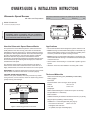
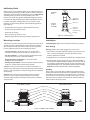
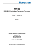
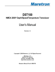
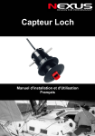
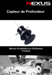
Log Transducer
- Solid State -
Installation and Operation Manual
English
OWNER’S GUIDE & INSTALLATION INSTRUCTIONS
Ultrasonic Speed Sensor
69920-1
Ver 1.0
17-263-01
rev. 01
01-08
11/02
with Valve and Temperature
Record the information found on the cable tag for future reference.
Part No._________________Date___________Frequency________kHz
Model CS4500-610
U.S. Patents 5,186,050; 6,426,918
IMPORTANT: Please read these instructions
completely before proceeding with the installation.
These instructions supersede any other instructions in
your instrument manual if they differ.
How the Ultrasonic Speed Sensor Works
The speed sensor uses ultrasonic pulses to collect echoes from
small particles in the water as they pass under two transducers
embedded in the insert (see Figure 1). These transducers monitor
the particles in their respective beams. As the boat travels through
the water, both transducers “view” the same stream of particles.
Because it takes time for particles to travel between the two
transducers, the aft transducer detects the particles later than does
the fore transducer. By measuring this time lapse, the instrument
calculates the boat speed.
The ultrasonic speed sensor requires particles in the water to
obtain echoes. If the boat is airborne even for a short time or in
highly aerated water, the sensor will measure an incorrect speed.
IMPORTANT: The ultrasonic speed sensor must be in good contact
with the water at all times for the sensor to function properly.
CAUTION: NEVER USE SOLVENTS!
Cleaners, fuel, paint, sealants, and other products may contain
strong solvents, such as acetone, which can attack many plastics
greatly reducing their strength.
Applications
• Not recommended for boats designed to pull air under the hull.
• Plastic housing recommended for fiberglass or metal hulls only.
Never install a plastic sensor in a wood hull since swelling of the
wood may overstress the plastic causing a fracture.
• Bronze housing recommended for fiberglass or wood hulls only.
Never install a bronze housing in a metal hull because electrolytic
corrosion will occur.
• Never install a metal housing in a vessel with a positive ground
system.
• Ultrasonic insert must be installed in a housing with a valve.
Raymarine ST-40—The ultrasonic insert is too long for the
existing housing. Install the new housing.
Tools and Materials
Water-based antifouling paint (mandatory in salt water)
Safety goggles
Dust mask
Electric drill with 10mm or larger chuck capacity
scanning transducer
hull
FORE
AFT
vessel direction
Drill bit
3mm or 1/8"
Hole saw
51mm or 2"
Sandpaper
Mild household detergent or weak solvent (such as alcohol)
File (installation in a metal hull)
Marine sealant
Additional washer [for aluminum hull less than 6mm (1/4") thick]
particle stream
Slip-joint pliers (installing a metal housing)
Installation in a cored fiberglass hull (see page 3):
Hole saw for hull interior
Figure 1. Monitoring particles in the water
60mm or 2-3/8"
Fiberglass cloth and resin
or Cylinder, wax, tape, and casting epoxy
Antifouling Paint
Marine growth can accumulate rapidly on the ultrasonic sensor’s
surface reducing performance within weeks. Surfaces exposed to
salt water must be coated with antifouling paint. Use water-based
antifouling paint only. Never use ketone-based paint, since
ketones can attack many plastics possibly damaging the sensor.
ultrasonic
insert
outside wall
below
lowest O-ring
It is easiest to apply antifouling paint before installing the sensor,
but allow drying time. Reapply paint every 6 months or at the
beginning of each boating season. Paint the following surfaces
(see Figure 2):
active face
housing
& valve
assembly
• Outside wall of the ultrasonic insert below lowest O-ring
inside bore
of housing
up 30mm (1-1/4")
• Active face of the ultrasonic insert
• Exterior lip of housing
exterior lip
• Bore of housing up 30mm (1-1/4")
Figure 2. Antifouling paint
• Blanking plug below lowest O-ring including exposed end
Mounting Location
Installation
Turbulence-free water must flow under the ultrasonic sensor at all
speeds. Choose an accessible spot with a minimum of 200mm
(8") of headroom inside the vessel to allow for the height of the
housing, tightening the nuts, and removing the insert.
Cored fiberglass hull—Follow separate instructions on page 3.
Hole Drilling
Warning: Always wear safety goggles and a dust mask.
• Fin keel sailboats—Mount the sensor on or close to the
centerline and forward of the fin keel 150–300mm (1/2–1').
1. Drill a 3mm or 1/8" pilot hole from inside the hull. If there is a rib,
strut, or other hull irregularity near the selected mounting
location, drill from the outside.
• Full keel sailboats—Locate the sensor amidships and away
from the keel at the point of minimum deadrise.
2. Using the 51mm or 2" hole saw, cut the hole from outside the hull.
• Displacement hull powerboats—Locate the sensor
amidships near the centerline.
3. Sand and clean the area around the hole, inside and outside, to
ensure that the sealant will adhere properly to the hull. If there is
any petroleum residue inside the hull, remove it with either mild
household detergent or a weak solvent (alcohol) before sanding.
Metal hull—Remove all burrs with a file and sandpaper.
• Planing hull powerboat—Mount the sensor well aft to ensure
it will be in contact with the water at high speeds.
Caution: Do not mount the sensor in an area of turbulence or
bubbles: near water intake or discharge openings; behind strakes,
fittings, or hull irregularities; or behind eroding paint (an indication
of turbulence).
Bedding
Apply a 2mm (1/16") thick layer of sealant around the lip of the
housing that contacts the hull and up the sidewalls of the housing.
The sealant must extend 6mm (1/4") higher than the combined
thickness of the hull, washer(s), and hull nut (see Figure 3). This
will ensure there is sealant in the threads to seal the hull and to
hold the hull nut securely in place.
Caution: Never mount the sensor directly ahead of a depth
transducer, since turbulence generated by the housing will
adversely affect the depth transducer’s performance, especially
at high speeds.
P120 plastic housing
B120 metal housing
ultrasonic insert
cap nut
safety wire
hull nut
washer
marine
sealant
hull
Figure 3. Bedding and installing
2
marine
sealant
Installing
Caution: Never pull, carry, or hold the ultrasonic insert by
the cable as this may sever internal connections.
1. From outside the hull, push the housing into the mounting hole
using a twisting motion to squeeze out excess sealant (see
Figure 3). Align the arrow on the lip of the housing pointing
forward toward the bow. If the sensor is not installed on the
centerline, angle the housing slightly toward the centerline to
align it with the water flow.
pour in
casting
epoxy
3. Screw the hull nut in place being sure the notch on the upper rim
of the housing and the corresponding arrow on the lip are still
positioned forward toward the bow (see Figures 3 and 5). (If your
plastic housing has wrenching flats, do not clamp tightly, possibly
causing the housing to fracture.)
Plastic hull nut—Hand-tighten only. Do not over-tighten.
Metal hull nut—Tighten with slip-joint pliers.
Wood hull—Allow the wood to swell before tightening the hull
nut securely.
4. Remove any excess sealant on the outside of the hull to ensure
smooth water flow over the ultrasonic insert.
Warning: The O-rings must be intact and well
lubricated to make a watertight seal.
5. After the sealant cures, inspect the O-rings on the ultrasonic
insert (replace if necessary) and lubricate them with the silicone
lubricant supplied.
Important: For the sensor to work properly, the bottom of the
insert must be flush with the bottom of the housing.
6. Slide the ultrasonic insert into the housing with the arrow on the
top pointing forward toward the bow. Seat it into place with a
pushing twisting motion until the key fits into the notch. The arrow
on the tip of the insert, the notch in the housing, and the arrow on
the lip will be aligned. Be careful not to rotate the housing and
disturb the sealant. Screw the cap nut in place and handtighten only. Do not over-tighten (see Figure 3).
Warning: Always attach the safety wire to prevent the insert
from backing out in the unlikely event that the cap nut fails or is
screwed on incorrectly.
7. Attach the safety wire.
Plastic housing—Attach the safety wire to one eye in the hull
nut. Lead the wire in a counterclockwise direction and thread it
through one eye in the cap nut, along the side of the cap nut,
through the second eye in the cap nut, and the second eye in
the hull nut. Twist the wire securely to itself.
Metal housing—Wrap one end of the safety wire tightly around
the housing and twist it together with the long end. Lead the wire
straight up and through the eye in the cap nut. Loop the wire
back down and twist it securely to itself.
8. To wire the ultrasonic sensor, follow the instructions, “Wiring” on
page 5.
inner skin
core
hull thickness
solid or hollow cylinder
2. From inside the hull, slide the washer onto the housing.
Aluminum hull less than 6mm (1/4") thick—Use an
additional rubber, fiberglass, or plastic washer. Never use
bronze since electrolytic corrosion will occur. Never use wood,
since it will swell possibly fracturing the plastic housing.
9-12 mm
(3/8-1/2")
larger than the
hole through the
hull’s outer skin
outer skin
Figure 4. Preparing a cored fiberglass hull
Checking for Leaks
Warning: Never install a thru-hull sensor and leave the boat in the
water unchecked for several days.
When the boat is placed in the water, immediately check around
the thru-hull sensor for leaks. Note that very small leaks may not
be readily observed. It is best not to leave the boat in the water for
more than 3 hours before checking it again. If there is a small
leak, there may be considerable bilge water accumulation after 24
hours. If a leak is observed, repeat “Bedding” and “Installing”
immediately.
Installation in a Cored Fiberglass Hull
The core (wood or foam) must be cut and sealed carefully. The
core must be protected from water seepage and the hull must be
reinforced to prevent it from crushing under the hull nut allowing
the housing to become loose.
Warning: Always wear safety goggles and a dust mask.
1. Drill a 3mm or 1/8" pilot hole from inside the hull. If there is a rib,
strut, or other hull irregularity near the selected mounting location,
drill from the outside. (If the hole is drilled in the wrong location,
drill a second hole in a better location. Apply masking tape to the
outside of the hull over the incorrect hole and fill it with epoxy.)
2. Using the 51mm or 2" hole saw, cut the hole from outside the
hull through the outer skin only (see Figure 5).
3. From inside the hull, use the 60mm or 2-3/8" hole saw to cut
through the inner skin and most of the core. The core material
can be very soft. Apply only light pressure to the hole saw after
cutting through the inner skin to avoid accidentally cutting the
outer skin.
4. Remove the plug of core material so the inside of the outer skin
and the inner core of the hull are fully exposed.Sand and clean
the inner skin, core, and the outer skin around the hole.
Caution: Completely seal the hull to prevent water seepage into
the core.
5. If you are skilled with fiberglass, saturate a layer of fiberglass cloth
with a suitable resin and lay it inside the hole to seal and strengthen
the core. Add layers until the hole is the correct diameter.
Alternatively, a hollow or solid cylinder of the correct diameter
can be coated with wax and taped in place. Fill the gap between
the cylinder and hull with casting epoxy. After the epoxy has set,
remove the cylinder.
6. Sand and clean the area around the hole, inside and outside, to
ensure that the sealant will adhere properly to the hull. If there is
any petroleum residue inside the hull, remove it with either mild
household detergent or a weak solvent (alcohol) before sanding.
7. Proceed with “Bedding” and “Installing” on page 2.
3
Operation, Maintenance, and Repair
How the Valve Works
The sensor incorporates a self-closing valve which minimizes the
flow of water into the vessel when the ultrasonic insert is removed.
The curved flap valve is activated by both a spring and water
pressure. Water pushes the flap valve upward to block the
opening, so there is no gush of water into the boat.
WARNING: THE VALVE IS NOT A WATERTIGHT SEAL!
Always install the ultrasonic insert or the blanking plug secured
with the safety wire for a watertight seal.
top view of
ultrasonic
insert
blanking
plug
large O-ring
ultrasonic
insert
medium O-ring
small O-ring
Using the Blanking Plug
To protect the ultrasonic insert, use the blanking plug when:
active face
• The boat will be kept in salt water for more than a week.
• The boat will be removed from the water.
• Aquatic growth build-up is suspected due to inaccurate
readings from the instrument.
valve
assembly
valve assembly with
flap valve, spring,
and retainer pin
notch
Warning: The O-rings must be intact and well
lubricated to make a watertight seal.
1. Inspect the O-rings (replace if necessary) and lubricate them
with the silicone lubricant supplied or petroleum jelly (Vaseline®)
(see Figure 5).
snap ring
housing
housing
BOW •
2. Assemble the blanking plug. Place the cap nut on top of the
plug and attach the pull ring to capture the cap nut.
3. Remove the ultrasonic insert from the housing by removing the
safety wire from the cap nut (see Figure 3).
4. Unscrew the cap nut to jack the insert out of the housing. This
will remove the cap nut and insert as a single unit.
Warning: Always attach the safety wire to prevent the insert
from backing out in the unlikely event that the cap nut fails or is
screwed on incorrectly.
5. Slide the blanking plug into the housing with the arrow pointing
forward toward the bow (see Figure 5). Seat it into place with a
twisting motion until the key fits into the notch. Screw the cap
nut in place and hand-tighten only. Do not over-tighten.
Reattach the safety wire (see Figure 3).
Servicing the Ultrasonic Insert
Caution: The active face of the ultrasonic insert is very fragile and
easily damaged. Do not scratch, gouge, or sand it with coarse
sandpaper.
Aquatic growth will seriously affect the ultrasonic insert’s performance.
Clean the active face with a dull putty knife being careful to avoid
scratching the surface (see Figure 5). If fouling is severe, lightly wet
sand the surface with fine grade (#320) wet/dry paper.
O-rings must be free of abrasions and cuts to ensure a watertight
seal. Install the large O-ring near the cap nut, the medium O-ring
below it, and the small O-ring near the active face. The three
remaining O-rings are placed in similar positions on the blanking
plug (see Figure 5).
Servicing the Valve Assembly
Should the valve fail, remove it for servicing. A replacement O-ring
and Valve Kit 33-450-01 is available.
1. On the blanking plug, inspect (replace if necessary) and lubricate
the O-rings with silicone lubricant or petroleum jelly (Vaseline®).
4
Figure 5. Servicing
2. Remove the ultrasonic insert from the housing (see Figure 3).
3. Remove the snap ring from the valve assembly using a
screwdriver to pry the end of the ring free (see Figure 5).
4. Slide the valve assembly upward and out of the housing slowly.
Note: The flap valve retainer pin is a loose slip-fit and may slide
out when the assembly is removed.
5. Slide the blanking plug (or ultrasonic insert) into the housing
with the arrow on the top pointing forward toward the bow. Seat
the plug into place with a twisting motion until the key fits into
the notch. Screw the cap nut in place and hand-tighten only.
Do not over-tighten. Reattach the safety wire (see Figure 3).
6. Clean, repair, or replace the valve assembly so the flap valve
moves freely and seats against the valve housing (see Figure 5).
7. Remove the blanking plug. Slide the valve assembly into the
housing with the flap valve pointing downward. Insert the snap ring
being certain that it locks into the groove in the housing wall.
Warning: Always attach the safety wire to prevent the insert
from backing out in the unlikely event that the cap nut fails or is
screwed on incorrectly.
8. Slide the ultrasonic insert into the housing with the arrow on the
top pointing forward toward the bow. Screw the cap nut until
there is resistance.Seat the ultrasonic insert into place by
rotating it until the key clicks into the notch. Continue to screw
the cap nut into place hand-tightening only. Do not overtighten. Re-attach the safety wire (see Figure 3).
Wiring
Tools and Materials
Pencil
Drill
Drill bit: 3mm or 1/8"
Cutting pliers
Phillips screwdriver
Wire strippers
Electrical tape
Blade screwdrivers
SERVER
power panel
(battery)
instrument
Locating the Junction Box and Cable Routing
sensor
Caution: Minimize electrical interference by separating the sensor
cables from other electrical wiring and the engine.
Figure 6. Cable layout
Caution: Be careful not to tear the cable jackets when passing
them through the bulkhead(s) and other parts of the boat.
1. Select a convenient, dry, mounting location for the waterproof
junction box, about 1–2m (3' – 5') from the instrument (see
Figure 6).
2. Route the sensor cable to the proposed location of the junction
box. Do not fasten the cable in place at this time.
3. Hold the junction box at the selected location and mark the
position of the four screw holes with a pencil.
Note: If the junction box will be mounted on a vertical surface, face
the compression bushings downward to avoid water seeping into
the box.
4. At the marked locations, drill a 3mm or 1/8" hole to a depth of
10mm (3/8"). Do not screw the junction box in place at this time.
5. Route the instrument cable to the junction box. Cut the cable
50cm (2') beyond the junction box to allow for wiring ease.
Do not fasten the cable in place at this time.
6. Route the power cable from the battery to the junction box.
Allowing 25cm (10") at each end for wiring ease, cut the cable
to length. Do not fasten the cable in place at this time.
Preparing the Cables
WARNING: The power must be “off” before proceeding.
1. Remove the junction box cover (see Figure 7).
2. Push approximately 200mm (8") of the power cable through the
left compression bushing, being careful not to damage the
circuit board.
3. Push approximately 200mm (8") of the instrument cable
through the center compression bushing, being careful not to
damage the circuit board.
4. Push approximately 200mm (8") of the sensor cable through
the right compression bushing. Be careful not to damage the
circuit board and the stripped wires.
Note: The grey wire is covered with protective sleeving and this
must remain in place.
5. Strip 60mm (2-1/2") of the outer jacket and foil shielding from
the cut ends of the power and instrument cables (see Figure 8).
screw hole (4)
6. Strip 11mm (3/8") of conductor insulation from the end of each
insulated wire in the power and instrument cables.
BRN
GRN
WHT
INSTRUMENT
BLK
RED
RED
RED
GRN
BRN
WHT
BARE
BLK
RED
BATTERY
SENSOR
grey
wire with
protective
sleeving
7. Protect the cable’s foil shielding from causing a short inside the
junction box. Wrap electrical tape around the jacket where the
wires emerge from the cable. The tape must overlap the wires a
minimum of 6mm (1/4").
remove outer jacket
60mm (2 1/2")
remove
insulation
11mm
(3/8")
compression
bushing (3)
From Battery
Use 2A Fuse
From Server
Log input
From Sensor
Figure 7. Junction box
cable
jacket
electrical
tape
Figure 8. Preparing the cable—instrument cable shown
5
Wiring the Junction Box
button
button
BRN
GRN
WHT
RED
INSTRUMENT
BLK
BATTERY
RED
GRN
BARE
BRN
WHT
BLK
RED
1. From outside the junction box, carefully pull each of the cables
in turn until only 13mm (1/2") of the cable jacket remains inside
the box (see Figure 9).
2. Starting with the battery cable, wire each cable in turn to the
corresponding terminal block. Follow the color code on the PC
board. Insert the stripped end of a wire in the hole in the
corresponding terminal. Simultaneously depress the adjacent
button using a small blade screwdriver. Release the button to
lock the wire in place. Be sure the stripped end of the wire is
inserted up to the insulation only. Do not include any insulation
inside the terminal. Gently tug on the wire to ensure it is locked
in place. Repeat this process until all wires are connected.
SENSOR
Caution: Sensor cable—Do not attempt to connect the bare
wire and grey wire. The bare wire has been cut off flush with the
cable jacket, and the grey wire has been covered with protective
sleeving. Do not allow these wires to short anything in the
junction box.
3. Hand-tighten the nut on each compression bushing to make a
waterproof seal.
4. Arrange the wires neatly inside the junction box being sure that
no bare wires are touching.
5. Attach the junction box cover with the screws provided for a
waterproof seal.
6. Using the screws provided, attach the junction box to the
selected mounting surface at the holes previously drilled.
Wiring the Instrument
To connect the instrument cable to the display, follow the
instructions in your instrument owner’s manual for connecting a
speed sensor. See the color code below.
Nexus Server
Red
B+ (5 to 15V)
Green
Green (GRN)
signal
Yellow
Bare
ground
Bare
Wite
White (WHT)
temperature
Jumper from Bare
Brown (BRN)
temperature
Wiring the Power Panel (Battery)
Warning: The power panel must have a 1/2 amp fast blow fuse or
breaker.
Cut off the bare wire flush with the cable jacket. To connect the
power cable to the power panel, see the color code below.
Red
Black (BLK)
+ 10 to 15 VDC
– VDC
Troubleshooting
No Speed Reading
• Is the ultrasonic insert installed in the housing and connected to
the junction box?
• Is the ultrasonic insert oriented with the arrow on the top
pointing forward toward the bow? If the insert cannot be seated
in the housing with the arrow pointing forward, check that the
arrow on the lip of the housing is pointing forward toward the
bow. If this is not the case, the housing needs to be reinstalled
with the proper orientation.
• Is power being supplied to the junction box? The power must be
10-15VDC. At lower voltages performance is degraded and the
unit will shut down. If there is no voltage, check the wiring.
AIRMAR
6
Figure 9. Wiring the Junction Box
• Are the wire connections at the terminals in the junction box
tight and properly stripped of insulation?
• Does the color of each wire match the color label on the PC
board?
Inaccurate Speed Readings
• If the ultrasonic speed sensor is “on” when the boat is
stationary, you may see a speed readout of a fraction of a knot
because of water movement under the hull.
• If the speed reading is consistently the same percentage higher
or lower than the true speed, the speed function within the
instrument needs to be recalibrated. Follow the instructions in
your instrument owner’s manual.
• If speed readings are inaccurate above about 10knots:
- The sensor is installed in turbulent water. The cause may be
water intake or discharge openings, strakes, fittings, hull
irregularities upstream of the sensor, or the shape of the hull
in that area. The sensor must be re-installed in another
location.
- The ultrasonic insert is covered with aquatic growth. See
“Servicing the Ultrasonic Insert” on page 4.
- Aerated water is flowing across the sensor because the boat
is designed to pull air under the hull. The sensor will not work
on this type of boat.
Replacement Parts
If you have purchased a plastic housing and have a wood hull or
desire greater strength, purchase a bronze housing. Obtain the
following parts from your marine dealer or instrument manufacturer.
Blanking
Plug
20-600
Cap Nut
Hull Nut
Housing, Washer
& Hull Nut
O-ring &
Valve Kit
04-234-1 (plastic)
04-004 (plastic) 33-340-02 (plastic)
33-450-01
02-131-01 (bronze) 02-030 (bronze) 33-340-01 (bronze)
Sensor Replacement
The information needed to order a replacement Airmar sensor is
printed on the cable tag. Do not remove this tag. When ordering,
specify the part number and date.
Copyright ©:
35 Meadowbrook Drive, Milford, New
Hampshire
03055-4613,
USA
Nexus
Marine
AB
TECHNOLOGY CORPORATION
www.airmar.com
Kuskvägen 4, 191 62 Sollentuna, Sweden
Tel: +46 -(0) 8 – 506 939 00. Fax: +46 -(0) 8 -506 939 01
www.nexusmarine.se
69920-1 Edition 1, For Solid State Log Tx
Copyright ©:
Nexus Marine AB
Kuskvägen 4, 191 62 Sollentuna, Sweden
Tel: +46 -(0) 8 – 506 939 00. Fax: +46 -(0) 8 -506 939 01
www.nexusmarine.se