1
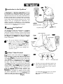
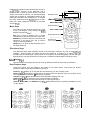
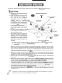
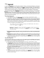
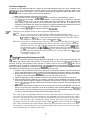
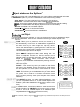
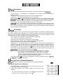
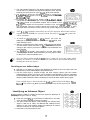
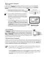
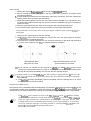
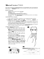
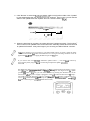
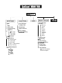
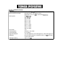
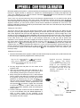
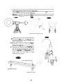
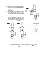
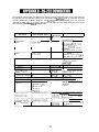
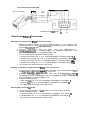
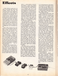
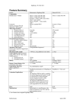
INSTRUCTION MANUAL NEVER USE YOUR TELESCOPE TO LOOK DIRECTLY AT THE SUN.
PERMANENT EYE DAMAGE WILL RESULT. USE A PROPER SOLAR FILTER
FIRMLY MOUNTED ON THE FRONT OF THE TELESCOPE FOR VIEWING
THE SUN. WHEN OBSERVING THE SUN. PLACE A DUST CAP OVER YOUR
FINDERSCOPE OR REMOVE IT TO PROTECT YOU FROM ACCIDENTAL
EXPOSURE. NEVER USE AN EYEPIECE-TYPE SOLAR FILTER AND NEVER
USE YOUR TELESCOPE TO PROJECT SUNLIGHT ONTO ANOTHER
SURFACE, THE INTERNAL HEAT BUILD-UP WILL DAMAGE THE
TELESCOPE OPTICAL ELEMENTS.
1 ntroduction to the SynScan
TM
The SynScanr" is a precision-engineered instrument
that will allow you to easily find and enjoy viewing night
sky treasures, such as planets, nebulea, star clusters,
galaxies and much more. The hand control allows you
to point your telescope at a specific object or even tour
the skies at the touch of a button. The user friendly
menu system allows automatic slewing to over 13,400
objects. Even an inexperienced astronomer can
master its variety of features in a few observing
sessions. Below is a brief description of the individual
components of the SynScanTM
hand controller.
Powering the SynScan
TM
The SynScanTMshould be powered by 11-15V DC
power supply (tip-positive) capable of producing
continuous current of minimum 2 amps. Correctly plug
the power cord into the 12V DC outlet on the the mount
(See Fig.a and b for HEQS mount, Fig.a-I and b-I for
EQ6 mount). Flip the Power Switch to the "on" position
to turn on the power.
Guider
to power supply
/
po$er switch
power indicator
The power indicator will flash when the
power is low. Continue to use the batten.
.at this point may damage the battev. The
power indicator will flash rapidly when
the power is extremely low. Continue to
use the same battery may damage the
SynScan " system.
T
S ynScan
TM
Hand Control
The SynScan " hand control cable for the HEQS has a
RJ-45 connector on both ends. Plug one end into the
hand control (Fig.c) and the other into the outlet on the
mount (Fig.b). Push the connector into the outlet until it
clicks into place. The SynScanTM
cable for the EQ6
mount has a RJ-45 connector on one end and DB9 on
the other. Plug the RJ-45 connector into the hand
control fig.^). Push the connector into the outlet until it
clicks into place. Plug the DB9 connector into the outlet
on the mount. Tighten the screws to secure the
connector in place (Fig.a-I). The RJ-11 6-pin port is
used for .RS-232 communications between the
SynScanTMand a computer or other devices. (See
"Linking with a Computei' for details.) The DC power
port allows independent use of the SynScanTM
hand
control for users who wish to browse the database
without connecting to the telescope fig.^).
T
The DC power port on the hand control is for
hand control stand-alone applications only.
For telescope applicaions, use the 12V DC
outlet on the mount.
To connect the SynScan to a PC, use only the
RS-232 cable provided with the mount.
The SynScanTM
Hand Control allows direct access to
all the motion controls of the telescope and a
database with a range of preset objects. The Hand
Control comes with a dual-line, 16 character display
screen that is backlit for comfortable viewing of the
telescope information and scrolling text. To explore
the many functions that the SynScanTM
has to offer,
there are 4 main categories of control on the Hand
Control (Fig.d):
Mode keys
The mode keys are located near the top, close to the LCD display. They include the ESC,
ENTER, and SETUP keys:ESC key is used to escape from a certain command or to go back a level in the menu tree. ENTER key is used to select the functions and submenus in the menu tree, and to confirm certain functional operations. SETUP key is a quick hot key that takes you to the Setup submenu. Display screen
I
..........................
Mode keys
----------
Directional keys
----------Dual purpose keys
-----------Scrollkeys
Directional keys
The directional keys allow complete control of the telescope at almost any step in the SynScanls
operation. These controls are locked out when the telescope is slewing to an object. They are
normally used to initially align, center objects in the eyepiece, and manual guiding. The left and right
directional keys can also be used to move the text curserwhen entering data to the hand control.
Scoll Keys (Fig.e)
The up and down scroll keys allow you to scroll up and down within the menu tree or selections.
Dual Purpose keys
These keys range from the middle to the bottom of the hand control. They serve two distinct
purposes -data entry and quick reference hot keys.
TOUR key (Fig.0 takes you on a preset tour across the sky you are currently under. RATE key (Fig.0 changes the speed rate of the motors when the direction keys are pressed. There
are 10 speeds to choose from: 0 (slowest) to 9 (fastest). UTILITY key (Fig.0 shows functions such as Show Position, Display Time...etc. USER key (Fig.0 gives access to up to 25 user-defined coordinates. ID key (Fig.0 identifies the object the telescope is currently pointing to. NGC, IC, M, PLANET, and OBJECT keys (Fig.g) allow direct access to SynScan " database of over
13,400 objects.
T
This section provides a step-by-step procedure on how to operate your SynScanrMhand control.
tial Setup 1. Perform the Polar alignment using the polarscope.
2. Point the telescope roughly to the
North Celestial Pole (or Polaris) if
you
are
in the
Northern
Hemisphere. Point to the South
Celestial Pole if in Southern
Hemisphere. Make sure the
counterweight rod is pointed down as seen in Fig.h. This will be the home position of the telescope. 3. Flip the Power Switch on the mount
to the "ON" position to turn on the
power.
4. The initial screen displayed on the hand control is the Version Screen. Press ENTER to proceed. 5. The hand control will display a warning concerning pointing the telescope at the sun without proper equipment. If you have read the
message already, pressing ESC will bypass the message and skip to the next step.
(Northern Hemisphere)
aID
Zenith
I
North Celestial Pole
Decl~natlon
Plane of local hor~zon
Plane of Celest~alEquator The hand control's red light will become diin~nerand the key pads will turn off if idle
for 30 seconds. Pressing any key turns it back on.
6. Enter the telescope's current latitudinal and longitudinal position using the numeric keypad.
First enter the longitudinal coordinate, followed by the latitudinal coordinate. Use the scroll
keys to choose between W or E, and N or S. Pressing the left or right directional keys will
move the cursor to the previous or next number. Press ENTER to confirm. The format you
enter should look like this: 123 04' W 49 09'N.
7. Enter your current time zone in hours (see Appendix C), using the scroll keys and numeric
key pad (+ for East, - for West). Press ENTER to confirm. The format you enter should look
like this if you are in Pacific Standard Time (PST): -08.
8. Enter the date in the following format mmlddlyyyy using the numeric keypad. Press ENTER
to confirm.
9. Enter your current local time using the 24 hr time mode (e.g. 2:00PM=14:00). Press ENTER
to view the time you just entered. If it is incorrect, press ESC to go back to the previous
screen. If correct, press ENTER again to proceed to the daylight saving setting.
10. If the date entered in step 8 falls between March and November, the SynScanTM
will prompt
"DAYLIGHT SAVING?". Use the scroll keys to make the selection and press ENTER to
confirm. If the date is out of the range between March and November, the SynScan will'" skip
the daylight saving setting and proceed to the next step.
11. After setting the daylight saving, SynScanTMwill display "Begin alignment?". Press "1" or
ENTER to start the alignment procedure. Press "2" or ESC to skip the alignment and exit to
the Main Menu.
If a mistake was entered into the SynScan hand control, press the ESC key to go back
to the previous menu. and press ENTER to start again.
TM
Star ~ l i ~ n r n e n t
In order for the SynScanT"to correctly point to objects in the sky, it must first be aligned to one to three
known positions (stars) in the sky. As the Earth rotates on its axis every 24 hours, astronomical objects
appear to move through the sky following an arc. W~ththe supplied information, the telescope can
replicate a model of the sky and the movements of astronomical objects. Star alignment can be done
anytime during the observing session by choosing Alignment under SETUP MODE, in the Main Menu.
There are three ways to align the SynScanTM
depending on your demand for accuracy. If you are using the
SynScanTM
for the first time, we recommend that you begin with the Three Star Alignment. In most cases,
this produces the most accurate alignment among the three methods. Before performing any of the
alignment methods, be sure that your finderscope is well aligned with the telescope tube. See the next
page for tips on how to choose the alignment stars. Below describes a step-by-step procedure on how to
perform the Three Star Alignment:
Three-Star Alignment
1. In the alignment screen, select 3-StarAlign using the scroll keys. Press ENTER to confirm.
2. The SynScan will provide a list of stars available in your current sky for you to choose as the first
alignment star. Using the scroll keys, choose an appropriate star from the list provided and press
ENTER. The telescope will start slewing towards it. When the telescope stops slewing, adjust its
position with the directional keys until the star is centered on the crosshairs in the finder scope.
Now look through the eyepiece and adjust the telescope so that the object is centered in the field
of view of the eyepiece. Press ENTER to confirm.
TM
The slewing speed can be adjusted by pressing on the RATE button. Then choose a
number between 0 (slowest) - 9 (fastest).
SynScan" will becp once when it has finished slening to an object. Do not try to
adjust the telescope before you hear the beep. SynScan'" will only respond to the ESC
key while slewing.
3. SynScanT"will provide a list of objects for the second alignment star. Choose a star using the scoll
keys and press ENTER. Repeat the centering procedure for the second star and press ENTER to
confirm.
4. SynScanTM
will once again provide a list of objects for the third alignment star. Choose a star from
the list and press ENTER. Once again, repeat the centering procedure for the third alignment star.
5. If appropriate stars have been chosen and aligned to, the SynScanTM
hand control will display
"Alignment Successful". Otherwise, the warning "Alignment Failed" will show and the alignment
will have to be done again.
Two-Star Alignment
Two-Star Alignment requires only two alignment stars but, without Cone Error Calibration (see Appendix
A), it may produce lesser pointing accuracy than the Three-Star Alignment. Below describes a step-bystep procedure on how to perform the Two-Star Alignment:
1. In the alignment screen, select 2-Star Align using the scroll keys. Press ENTER to confirm.
2. The SynScanrMwill provide a list of stars available in your current sky for you to choose as the first
alignment star. Using the scroll keys, choose a star you are most familiar with and press ENTER.
The telescope will start slewing towards it. When the telescope stops slewing, adjust its position
with the directional keys until the star is centered on the crosshairs in the finder scope. Now look
through the eyepiece and adjust the telescope so that the object is centered in the field of view of
the eyepiece. Press ENTER to confirm.
3. SynScanTM
will provide a list of objects for the second alignment star. Choose a star using the scoll
keys and press ENTER. Repeat the centering procedure for the second star and press ENTER to
confirm.
4. If appropriate stars have been chosen and aligned to, the SynScanTM
hand control will display
"Alignment Successful". Otherwise, the warning "Alignment Failed" will show and the alignment
will have to be done again.
One-Star Alignment
It requires only one alignment star but, without accurate polar alignment and cone error calibration (see
Appendix A), it may produce lesser pointing accuracy than the other alignment methods. Refer to the
HEQIEQG manual for information on how to perform accurate polar alignment. Below describes a stepby-step procedure on how to perform the One-Star Alignment:
1. Make sure the telescope has been polar aligned.
2. In the alignment screen, select I-StarAlign using the scroll keys. Press ENTER to confirm.
3. The SynScanTM
will provide a list of stars available in your current sky for alignment. Using the
scroll keys, choose a star you are most familiar with and press ENTER. When the telescope
stops slewing, adjust its position with the directional keys until the star is centered on the
crosshairs in the finderscope. Now look through the eyepiece and adjust the telescope so that the
object is centred in the field of view of the eyepiece. Press ENTER to confirm.
4. Once completed, SynScanTM
will display "Alignment Successfui".
w
Following is some pointers on how to choose appropriate alignment stars:
One Star: Choose a star closer to the Celstrial Equator (smaller declination absolute value). Two Star: Choose two stars that are on the same side of the meridian. and at least 3 hours apart in RA and 3"apart in Dec. If J ou suspect that the polar alignment is off by l o and above, choose
two stars that are well more than 3" but less than 60"apart in Dec.
Three Star For the first two alignment stars, follow the same guideline as choosing for the Tmo Star
Alignment. For the third alignment star, choose a star that is on the opposite side of the
meridian of the first two stars. Both first alignment star and third alignment stcv should
have an absolute value of 30 "to 70 "in Dec. If the first chosen star has a small Dec (<30°).
the Dec of the third star should be at least 50". The following formula can be used as a
guideline when determining the correlation between the first and third stars in Dec. 140'
>Abs(Dec 1)+Abs(Dec2)>6O0
Pointing Accuracy Enhancement (PAE)
The three star alignment methods provide alignment adequate for any visual observing purpose. For
applications that require extra high precision in a particular part of the sky, the SynScanT"provides a
Pointing Accuracy Enhancement (PAE) function to further improve the accuracy. The PAE can be
performed in up to 85 zones to cover the whole sky. The area(s) where the chosen alignment star(s) is located
should be already mapped out accurately by the SynScanTM.
Further accuracy enhancement is not necessary.
The following provides a step-by-step procedure on how to perform PAE:
1. Choose a star as reference object from a star chart or planetarium software. This star should be a
known, bright object that is currently located in the same part of the sky with the object of your interest.
2. Find the reference object in the SynScanTM
hand control database and go-to the object. If the mount
is under the control of the planetarium software, click on the object to slew to it.
3. Adjust the telescope so that the reference object is in the center of the eyepiece or CCD view.
4. Press and hold down the ESC key for 2 seconds. The hand control will display "Re-center" and the
name of the reference object will appear in a blinking mode (3 times). If the go-to command is sent
from the planetal-iumsoftware, instead of the name of the object, the hand control will display "Last
goto object".
5. Make sure that the reference object is still in the center of the view and press ENTER. If you do not
wish to record the result, press ESC to abort the operation. After pressing ENTER, the SynScanT"
will record the amount of pointing inaccuracy and recalculate the model of the sky. Now the pointing
accuracy of this particular part of the sky should be greatly improved.
The result for the star alignments and PAE is stored in the hand control even after the power has
been shut off. You will only need to perform the star alignment once as long as these two criteria
are met: 1 The telescope is moved to its home position (Park the telescope) before turning off the
power. 2. The telescope setup. including the mount, has not been moved. Accessory change is
acceptable as long as it is done with great caution. When thc hand control is turned on for the ncxt
time. make sure that the time entered during initial setup is based on the same source as last time.
For example, if you enter the time on your watch during this observing session, the time you enter
next time should also be read from your watch.
0bject database in the SynScan
TM
The SynScanrMcomes with a vast database with over 13,400 objects coordinates and information
all available in the palm of your hand. The database contains the following catalogs:
Solar System - The other 8 planets of our solar system, plus the Moon.
Named Star - A list of 212 best known stars from the SynScanTM
database.
*NGC - 7,840 of the brightest deep sky objects from the Revised New General Catalog.
IC - 5,386 of standard stars and deep sky objects from the Indexed Catalog. Messier - Complete list of 110 Messier objects. Caldwell -
Complete list of 109 Caldwell objects.
Double Stars - Includes 55 well-known double stars.
Variable Stars - Includes 20 will-known variable stars.
Selecting an Object
Once the telescope has been aligned. You can now access and view the 13,400 different objects
in the SynScanTM
database. There are three methods of selecting a celestial object to view:
TOUR - Takes you on a preset tour across your current sky. It will automatically choose from the database the brightest and most beautiful deep-sky objects for your viewing pleasure. Use the down scroll key to view through the deep sky objects. Choose the desired object by pressing ENTER. It will show the coordinate of the chosen object. Pressing ENTER once more will cause the telescope to slew to the object. M, NGC, IC - These shortcut keys give you access to the most popular celestial catalogues to date. Each Catalog has a set number of objects to choose from. Use the numeric keys to select an object by entering its number. Pressing ENTER will display its coord~nate. Primary information such as size, magnitude, and constellation are obtained by pressing the scroll keys. Pressing ENTER once more will cause the telescope to slew to the object.
PLANET - This shortcut key takes you straight to the Planets
sub menu in the database. Use the scroll keys to scroll through
the list of planets in our solar system. Press ENTER to view its
coordinates, and ENTER once more to slew to the planet.
USER - This will take you to the database that you have defined
for yourself. You can enter a new location or recall the objects
that have been previously saved (see Using the User Defined
Database).
The OBJECT key takes you to the Objects Catalogue, where
you have complete access to over 13,400 celestial objects in the
and the menu
database. (See Object database in the SynScanTM
tree.)
a
D
a@
aD
B@@
Be@
a
D
In the Main Menu, scroll down to OBJECT CATALOG and press
ENTER. Similar to the OBJECT key, this gives you the complete
access to all 13,400 celestial objects in the database. (See
and the menu tree.)
Object database in the SynScanTM
*NGC 2000.0 database, edited by Roger W Sinnott, copyright by Sky Publishing Corporation. Used with permission.
Utility Functions
Utility Functions are useful tools that provide simple, one-step processes to your SynScanTM:
Show Position - This displays the coordinates of the location where the telescope is currently pointed. Display Time - This displays the local time and local Sidereal time. Park Scope - This moves the telescope to the Home position. Inquire Version - This submenu displays the hardware, firmware, and database version of the
hand control. If the hand control is connected to the mount, this menu will also display
SynScanTM
the firmware version of motor control board. Use the scroll keys to view the version numbers.
PEC Training - See section Periodic Error Correction for information.
LCDlLED Tuning - This submenu allows adjustments of the following: the brightness of the
LCD backlit, the darkness of the LCD lettering, and the brightness of the LED backlit of the
keys. Use the scroll keys to select the desired tunning. Press the RIGHT or LEFT directional
key to increase or decrease value.
S e t u p Functions
The Setup functions allow you to change any system variable or information regarding location,
time, date, and alignment configurations. To access the Setup Functions, either press SETUP key
on the key pad or scroll to SETUP under menu option using the scroll keys. Below lists the
different types of functions available to you, and their purposes.
Date -Allows you to change the date entered at the initial setup. Time -Allows you to change the current time. Observing site -Allows you to change the current location. Daylight Savings -Allows you to change the Daylight Savings option.
Alignment -Allows you to perform the star alignment.
Set Backlash - This feature allows you to insert a value for each axis to compensate for its
backlash. For better pointing accuracy, it is important that the backlash value is set to be
equal or greater than the real amount of backlash between the gears. The default setting of
the backlash is 10' 00" (10 arcmin. and 0 arcsec.). Use the numeric keys to enter the
desired value and press the RIGHT directional key to move the cursor to the next digit. First
set the value for R.A. Press ENTER to proceed to Dec.
Set Tracking
Sid. Rate: This activates tracking in Sidereal rate (R.A. Tracking). Lunar Rate: This activates tracking in Lunar rate (R.A. Tracking). Solar Rate: This activates tracking in Solar rate (R.A. Tracking). PEC + Sidereal Rate: Sidereal rate with Periodic Error Compensation. Stop Tracking: This stops the tracking instantly. Auto Guide Speed -
When using an autoguider, this sets the guiding speed to I X , 0.75X,
0.5X, 0.25X, or 0.125X sidereal rate.
1
Using the User Defined Database
SynScanl" allows you to save up to 25 objects in the user defined database.
Saving an object to the database
1. In the Main Menu, use the scroll keys to scroll down the list until you
find Object Catalog. Press ENTER.
2. Select User Defined in the Object Catalog scroll list and press
ENTER.
The User Defined menu can also be accessed by pressing the quick
reference hot key "USER" (number 9) Fig I
-
4. The first available selection in the Object Catalog is Recall Object. This is where you select previously-saved objects to view. Use the scroll keys to scroll down to "Input Coordi.>" and press ENTER. 5. The SynScanTMstores the user-defined objects in two formatsR.A/Dec and AltIAz. Press 1 for the R.A/Dec. format and 2 for the
Enter RA-DEC:
Alt-Azimuth format.
2 2 h 4 6 . l m +90°00
6. By default the SynScanTMwill display the R.A./Dec or AltIAz
coordinates where the telescope is currently pointed. In the case of R.A/Dec format, the coordinate readout will be similar to this: "22h46.lm +90~00"'
(Fig.m) which means 22 hours and 46.1 minutes in R.A. and "+90"00"' in Dec. Change
the coordinates using the numeric keypad and scroll keys. Use the RIGHT or LEFT
directional keys to move the cursor to the next or previous digit. Press ENTER to save.
@D
B l
If the R.A./Dec coordinate entered does not exist, the SynScan hand control will not
respond when the ENTER key is pressed. Check the entry for inistake and re-enter the
correct coordinatc.
M
7. To store an object/location in AltIAz format, first point the telescope to the desired location to obtain the AltIAz value, then press ENTER to save. 8. After the coordinates have been saved, the SynScan'" will display an User Object number as shown in Fig.n. Use the scroll keys to change to the number you wish to represent the coordinates and press ENTER. 9. The SynScanrMwill display "View Object?" and the User Object number you just entered. Press ENTER to go to the object or ESC to return to the lnput Coordinate menu. &
aB
The User Object number displayed may not be a vacant one. If you are unsure which
numbers are vacant, it is recommended that you first check for the available numbers by
recalling the saved user objects.
Recalling an user defined object
1. See Step 1-4 of "Saving an object to the database" for details on how to access to the User
Defined menu. Select Recall Object and press ENTER.
2. Use the scroll keys to browse through the User Object number until the number
representing the object you wish to view is present. Press ENTER to show its coordinate.
Press ENTER again to slew to the object. The hand control will not respond if a vacant User
Object number is selected. Use the scroll keys to choose another number and try again.
If the recalled object is below horizon, the SynScanr"hand control will display "Belo\w
Horizon ! ! Try another obj ." and automatically return to the Recall Object menu.
Identifying an Unknown Object
SynScanrMhas the ability to identify the unknown object the telescope is
currently pointing at. To do so, simply:
1. Press the ID key (Fig.0) or scroll down to IDENTIFY in the main menu and press ENTER to identify the object. 2. The hand control will display a list containing the closest known object in each M, IC, NGC, and Named Star catalogs and its distance to the exact location where the telescope is pointed. Use the scroll keys to view these objects. 3. Press ESC to exit from this function.
Linking with A Computer -
Another feature of SynScanTM
is the ability to connect to a computer via a serial communication
cable. Many commercially available planetarium softwares can be used to control SynScanTM.
SynScanT"Version 3.00 and later is compatible with Celestron 5i/8i and NexStar GPS command
protocol.
1. Make sure that the telescope has been aligned.
2. Connect the RS-232 cable to the RJ-11 connector on the hand control and to the COM-port of your computer (Fig.p)
Do not use RS-232 cable other than the one provided to connect between the hand control and your computer. It
may damage your computer or the hand control. If you are making your own cable based on the information provided in Appendix B, make sure that only pin 2, 3 and 5 connect to the com connector on your computer.
3. In the planetarium software of your choice, choose "Celestron NexStar 5i" or "Celestron 8/9/11 GPS" in the driver setup menu and follow the instructions provided by your program to establish the connection to the telescope. The SynScan'" should be under the full control of your computer once the connection is successfully established.
4. When you are finished, follow the instructions provided by
your software to close the connection to the telescope.
Hand Control
Cb53
RJ- 11 a
RJ-11 Pin-outs
654321
I=
2=
3=
4=
5=
6=
EXPD+
-rD
GND
EXPDRD
+12v
See Appendix B for
more information on
RS-232 connection.
A u t o Guiding
The SynScanrM
has a designated autoguider interface on the mount for use with
an auto guider (see Fig.a, a-I). The pin-outs on the 6 pin modular connector is ST-4 compatible and can be used for most autoguiders on the market. Refer to
Fig.q when connectirlg the autoguider cable to the SynScan and calibrating the
autoguider. Relay box can be added for extra protection. Note that the four inputs are active-low, with internal pull-ups. Guiding speed can be adjusted using the
Auto Guide Speed function in the Setup Menu. TM
654321
I=
2=
3=
4=
5=
6=
NC
Ground
+RA (left)
+DEC (up)
-DEC (down)
-RA (right) Periodic Error Correction
Periodic Errors are found in almost all worm gears due to slight eccentricities and misalignments. The
PEC (Periodic Error Correction) function provides a manual correcting method to reduce the amplitude of
can
the worm errors. By recording a full cycle of guiding actions versus motor shaft angle, SynScanTM
work to compensate for the drifting in the RA sidereal tracking caused by the periodic errors. Below
describes a step-by-step procedure on how to perform the PEC:
PEC Training function is recommended for advanced users interested in long-exposure
astrophotograhy only. Careful guiding is required. Regular sidereal tracking is adequate for
all casual visual use of the SynScan" and PEC Training is not required.
Required acccssory: Illuminated reticle eycpiccc with double crossline pattern capable of
producing at least 300X magnification in combination with your telescope. The true field of
view should not exceed 10 arc min. See "Choosing the appropriate eyepiece" in the
HEQ5lEQ6 manual for more information on calculating the field of view.
PEC Training
1. Perform the accurate PolarAlignment method (see the HEQ5lEQ6 manual).
2. Slew or manually point the telescope to a star with smaller DEC coordinate. This object will be
used as the guide star.
3. Activate Sidereal Tracking from the Setup Menu (see Setup Functions). Once the tracking has
started, press ESC to go back to the Setup Menu.
4. Rotate the reticle eyepiece until one set of the lines becomes parallel to (or matches) the R.A.
movement of the telescope (see step 2 to 4 of the Cone Error Calibration for more information on
how this is done.)
5. Move the guide star back at the center of the eyepiece view using the direction keys.
6. On the hand control, select PEC Training in the Utility Functions and press ENTER.
Utility Functions can be easily accessed by pressing the UTILITY quick reference hotkej on
the keypad.
7. Select the R.A. guide speed for the PEC training.
8. The SynScan'" hand control will display the current time once the guide speed is selected,
indicating that the recording has begun.
9. Using the LEFT or RIGHT direction key only, move the telescope so the guide star remains at
the center of the eyepiece view (Fig.r, s). Repeat whenever necessary.
The Guide star drifts
away from the center
Adjust the telescope to move the
guide star back to the center
10. For 8 minutes (10 minutes and 30 seconds for HEQ5), the EQ6 SynScanr" hand control
records the manual guiding actions in order to characterize the periodic errors. Pressing ESC
will stop the recording immediately and exit from the PEC training function.
Guiding actions are recorded cven when the PEC training is stopped midway. 111this case, the
PEC+Sidereal tracking will not be accurate until a full cycle of the PEC training is performed.
11. The SynScan'" will beep and display "Record completed" when the training time is up. Press
any key to exit from the PEC training.
Play back the PEC record
PEC tracking can be activated under the Setup Menu or pressing the SETUP quick reference hotkey on the
keypad when needed. In the Setup Menu, choose Set Tracking, then PEC+Sidereal. SynScan'" will play back
the corrections you made during the PEC training cycle and start tracking with periodic error compensated.
&"
The SynS~an'~"
will continue to track in the PEC+Sidereal mode until another tracking
mode is selected. If the power is turned off while the SynScanmis under the PEC+Sidereal
mode, the hand control loses synchronization with the R.A. worm gear and the PEC
Training will have to be performed again when the power is turned back on. To avoid this,
be sure to return the telescope to its home position by selecting PARK S%OPl3 under the
UlILITY FUiVCTIONS before turning off the power.
Updating the SynScanT.Firmware
From version 3.0 onward, the SynScanr" firmware is user upgradeable. Users can download the
latest version of the SynScanTM
firmware from the Sky-Watcher web site and easily update their
hand controls.
System requirements
SynScanrMHand Control of version 3.0.or later. Windows95 or later An available RS-232C communication port on the PC. PC link cable that comes with the SynScanrM hand control. DC power supply with 7.5-1 5V/100mA output. Power plug should be 2.1mm diameter,
tip positive.
Preparing your PC for the update
1. Create a folder for all SynScan'" related files on your computer and name it SynScan.
2.Visit
website
at:
the
Support
Page
of
the
Sky-Watcher
http://www.SkywatcherTelescope.net/Support.html.
3. Download and save the SynScanTVirmware Loader to the SynScan'" folder on your
computer. You may create a shortcut on the desktop for quick access in the future. You
will only need to download this software once. Once it is saved on your computer, only
the firmware data file is needed for future updates.
4. Download and save the firmware data file named SynScanVXXXX.ssf to the SynScan
folder. (The XXXX indicates the version number of the firmware.)
Updating the SynScanrM
Hand Control
1. Plug the RJ-11 end of the PC link cable into the jack in the middle socket on the hand control fig.^). Push the connector into the hand control until it clicks into place. Plug the other end of the cable, the DB9 connector, to the RS-232 port on your PC. 2. Press and hold down the key "0" and "8" simutaniously, then plug the power cord into the hand control, as shown in Fig.t.
3. The hand control will give a beep, indicating a
successful start up. The SynScan'" will display: "SynScanT"Update Ver. x.x" on the LCD screen, as seen in Fig.u.
4. Run the SynScanFirmwareLoader software on your PC. Once the program is launched, you should see a window as Fig.v. The "HC.Version"
button provides the version number of the hardware, firmware and database of your hand control. It is for your reference only. You will not need it for the update. (
II
SynScan updatf
Ver.
1.1
1
\ mm@1
I
5. Click "Browse" to select the SynScanVXXXX.ssf file in the SynScan folder. Click "Update"
l o start downloading the new firmware into your SynScan hand control. You will see the
status of the update below the "Update" and "HC. Version" buttons fig.^).
TM
SynScan F~rmwareLoader
10
Flrmware F l e
Browse
]
HC Yerson
I
1
6. When the download is complete, the status will show "Update Complete". The SynScan
hand control is now updated to the newest firmware. Generally it takes about 30 seconds
to update the firmware. It may take longer if you are using an USB-to-RS232 converter.
TM
If the error message "Can not connect to a SynScan hand control" is shown, check the cable
connection and the PC link cable itself. Make sure it is all in good working condition. Close all
applications that mnay be occupying the RS-232 port and t v again.
If you receive the error message "Firmware update failed...", reset the hand control by
removing the power plug and thcn re-connecting it. Repeat the update procedurc.
By default, the data coinlnunication rate behleen Sq nScanTM
hand control and the PC is set to
be I LSkbps The RS-232C port on some PCs ma) not support such high rate If the update
process Calls after a fe\+ tries, you can reduce the rate by pressing the "SETUP" key on the
hand control aftcr the power supply is plugged in This uill reduce the data rate to 9 6 kbps .
The LCD screen will show the word "Lo" in the lomer right hand comer to indicate that it is
now in 1014 communication rate. The steps for updating the filmware remain the sane except
that now it takes longer to conlplete (about 240 seconds).
I MAIN MENU I
I
F
1
OBJECT CATALOG
Show Position
Sqlar System
Display Time
Observ. Site
Park Scope
Daylight Saving
Inquire Version
Alignment
1
1-Star Align.
2-Star Align.
3-Star Align.
t
LCDlLED Tuning
set Backlash set Tracking Sidereal Rate Lunar Rate Solar Rate PEC + Sidereal Rate Stop Tracking L ~ u t Guide
o
Speed
0.75x
0.25X
0.125 x
i
PEC Training
Mercury
Venus
Mars
Jupiter
Saturn
Uranus
Neptune
Pluto
Moon
k Named Star
IC Catalog
1NGC Catalog
Caldwell Catalog
t
Double Star
Variable Star
L User Defined
t
Input Coordinate
Recall Object
SynScanTw
SPECIFICATIONS
Power Supply:
Motor type and resolution:
Slew speeds:
Gear Ratio:
Tracking Rates:
Tracking Modes:
Alignment Method:
Database:
Pointing Accuracy:
11 to 15 V DC 2Amp (Tip positive)
Microstep driven 1.8" stepper motors.
Resolution: 0.144 arc sec (or 9,024,000 stepslrev.)
Rate 0 = 0.5X
Rate I = 1X
Rate 2 = 8X
Rate 3 = 16X
Rate 4 = 32X
Rate 5 = 64X
Rate 6 = 400X
Rate 7 = 500X
Rate 8 = 600X
Rate 9 = 800X
705
Sidereal, Lunar, Solar
R.A. tracking
One-Star Alignment, Two-Star Alignment, Three-Star Alignment
25 user defined objects. Complete M, NGC, and IC catalogues,
Total 13,436 objects
Up to 1 arc min
Generally speaking the SynScan produces pointing and tracking accuracies adaquate for most applications.
However, if higher precision is required, for example for astro-photography, accurate polar alignment and
"cone" error calibration may be required. See the manual for HEQ51EQ6 mount for information on accurate
polar alignment using the polarscope.
TM
"Cone" error is a common inaccuracy found on all German equatorial mount. It is a result from the optical
axis not being aligned to the R.A. axis of the mount. This affects the pointing accuracy of the SynScan'".
Three-Star Alignment automatically compensates for the "Cone" error. If you choose One-Star or Two-Star
Alignment method, you will need to perform manual mount calibration to eliminate the "cone" error. The
following calibration procedure should be performed before the initial use of the telescope and periodically
thereafter to ensure the accuracy.
Testing for Cone Error
This test is done at night using two bright stars located on the opposite side of the sky. Make sure the
telescope is properly polar-aligned using the polarscope. Perform the One-star Alignment using an eastern
star as the alignment star (see One-star Alignment). After the star alignment, choose a bright star on the
western sky from the SynScanTM
object database and have the telescope slew to the star. If the optical axis
is perfectly aligned to the R.A. axis, the telescope will accurately put the star in the center of the eyepiece.
In this case, there is no "cone" error in your telescope setup and you will not need to perform the
calibration. It is acceptable if the star is slightly off-center as long as it is in the eyepeiece view and close to
the center. Many factors determine the pointing accuracy of the SynScanrM,for example incorrect star
alignment, R.A. or Dec lock knob being lose, or "cone" error. If your telescope puts the star outside the
eyepiece view, you need to first determine whether it is "cone" error that causes the pointing inaccuracy. To
find out, simply move the telescope in R.A. axis by pressing the Left or Right direction key. If the star can
be moved into the eyepiece view without adjusting the Dec axis, it is likely that "cone" error exists in your
telescope setup.
Calibration Procedure
1. Insert the illuminated reticle eyepiece. Make sure that the telescope is properly set up and balanced, and
the finderscope is perfectly aligned with the telescope tube.
Step 2 to 4 is to identifi R.A. and Dec movements
in the reticle eyepiece. If you are already familiar
with the movcrnents, you may skip to step 5. 2. Find any bright star and place it in the center of the
eyepiece view. 3. Look into the eyepiece. Move the telescope in R.A.
axis using the R.A. direction keys on the hand control
while carefully observing the movement of the star. 4. Keep moving the the telescope in R.A. axis back and forth to keep the star within the eyepiece view. Rotate the eyepiece until the movement of the star becomes parallel to (or matches) any set of the lines (Fig.A-1).
This set of lines will represent R.A. movement in the
course of this procedure, and the perpendicular lines will represent Dec movement. Tigthen the set screws to secure the eyepiece in place. Make sure that the eyepiece will remain stationary when the telescope is being rotated. 5. Point the telescope to North and set the latitude scale to your local latitude using the altitude adjustment T-
bolts, or place Polaris on the crosshair of the polarscope if your polarscope is perfectly aligned with the rotation axis of the mount. Required accessory. Illuminated
reticle cyepiece with double
crossline pattern. Depending on the
design of your mounting plate
(dovetail bar), modifications may
be required. (See step 10 for the
required mechanism on the mounting plate.) movement eyepiece view
6. Loosen the R.A. lock knob and rotate the telescope around the R.A. axis until the
counterweight shaft is parallel to the ground. (Fig.A-2)
7. Using the Dec direction key on the hand control, adjust the telescope in Dec so Polaris sits
on the R.A. lines of the reticle eyepiece (Fig.A-3).
8. Wlthout moving the R.A. axis, adjust the azimuth control knobs to bring Polaris to the center
of the eyepiece (Fig.A-4). Adjustment in Dec axis using the hand control may be necessary.
Place Polaris on the R.A. line
9. Loosen the R.A. lock knob and carefully rotate
the telescope 180" in R.A. axis (Fig.A-5). This
should be done as accurate as possible using
the R.A. setting circle.
10. Once again, adjust the telescope in Dec so
Polaris sits on the R.A. lines of the reticle
eyepiece (see Fig.A-3).
11. Now take a closer look at the mount~ngplate
underneath the telescope tube. There should
be a set of screws on each end, next to the
tube ring lock~ngscrews (Fig.A-6). (If your
mounting plate does not have these screws or
screw holes, you will need to make
modification to the plate.)
tube ring locking screw
adjustment screws
12. Carefully nudge the telescope in horizontal
motion using only one finger while observing
the movement of Polaris through the eyepiece
(Fig.A-7). This is to determine which direction
(left or right) moves Polaris closer to the center
of the eyepiece.
13. Next step is to adjust the adjustment screws
on the mounting plate according to your
finding from step 12. If Polaris moves toward
the center when the telescope is nudged
toward your right hand side, You will need to
loosen the adjustment screws near the front of
the tube and tighten the ones closer to the
back of the tube (Fig.A-8), and vise versa
(Fig.A-9). Look into the eyepiece. Adjust the
screws just enough to place Polaris HALF the
distance back to the center (Fig.A-I 0).
Place Polaris here
14. Repeat step 7 to 13 until Polaris remains in the center of the eyepiece, or moves slightly
around the center, when the mount is rotate about the R.A. axis.
This calibration method can be applied on both refracting and reflecting
telescopes. Optical path of different telescope designs does not affect how the
telescope tube and tube lings should be adjusted on the mounting plate.
The SynScan " telescopes are designed to receive control commands sent from a computer via
the RS-232 port and RS-232 cable. Once connected, the SynScanTM
can be controlled by most
popular planetarium software program. The SynScanTMwill communicate with the personal
computer at 9600 bitslsec, no parity and stop bit. All angles are communicated with 16 bit angle
and communicated using ASCII hexadecimal.
T
I
Hand Control
Response
PC Command ASCII
Description
Useful to check
X#
1 ~ o t Azm-Alt
o
A ,
1 Goto Ra-Dec
Get Azm-Alt
Get RA-Dec
Cancel Goto
11s ~ o t in
o Progress
'7
E
M
L
Is Alignincnt Complete J
HC version
StopIStart Tracking
Notes
l
34AB, 12CE#
10 characters sent.
B=Command. 12AB=Azm,
comma, 4000=Alt If
command conflicts with slew
limits; there will be no action.
Scope must be aligned I
command conflicts with slev
limits, there will be no action
characters returned,
12AB=Azm, comma,
4000=Alt, #
Scope must be aligned
1#
o = N ~ l=Yes:
.
"
(characterzero
O=No, l=Yes
or I #
0# or 1#
-I
V
Tx
x= 0 (Tracking off)
x= 1 (Alt-Az on)
X= 2 (EQ-N)
x= 3 IEO-S)
o is~ ASCII
Two bytes representing V2.2
Alt-Az tracking requires
alignment
#
32-bit get Azm-Alt
L
z
34AB0500,
The last two characters will
always be zero.
34AB0500,
12CE0500#
The last two characters n i l
alwnys be zero
Physical Connection Diagram
RJ-11 Connector
RJ-11
NC
RD
GND
NC
TD
NC
I The Back of the DB9 Pinout
I
I
9
Additional RS232 Commands
Sending a track rate through RS232 to the hand control
1. Multiply the desired tracking rate (arc seconds /second) by 4. For example: if the
desired track rate is 120 arc seconds/second (proximately 8 times of sidereal rate),
then the TRACKRATE = 480.
2. Separate TRACKRATE into two bytes, such that (TRACKRATE =
3. TrackRateHighByte"256 + TrackRateLowByte). For example TRACKRATE = 480,
then TrackRateHighByte = 1, TrackRateLowByte = 224.
To send a tracking rate, send the following 8 bytes:
a. Positive Azm tracking: 80, 3, 16, 6, TrackRateHighByte, TrackRateLowByte, 0, 0
b. Negative Azm tracking: 80, 3, 16, 7, TrackRateHighByte, TrackRateLowByte, 0, 0
c. Positive Alt tracking: 80, 3, 17, 6, TrackRateHighByte, TrackRateLowByte, 0, 0
d. Negative Alt tracking: 80, 3, 17, 7, TrackRateHighByte, TrackRateLowByte, 0,0
4. The number 35 is returned from the hand control.
Sending a slow-Goto command through RS232 to the hand control
1. Convert the angle position to a 24bit number. Example: if the desired position is 220?,
then POSITION-24BIT = (220/360)*224 = 10,252,743
2. Separate POSITION-24BIT into three bytes such that (POSITION-24BIT =
PosHighByte * 65536 + PosMedByte * 256 + PosLowByte). Example: PosHighByte =
156, PosMedByte = 113, PosLowByte = 199
3. Send the following 8 bytes:
a. Azm Slow Goto: 80, 4, 16, 23, PosHighByte, PosMedByte, PosLowByte, 0
b. Alt Slow Goto: 80, 4, 17, 23, PosHighByte, PosMedByte, PosLowByte, 0
4. The number 35 is returned from the hand control.
Reseting the position of Az or Alt
1. Convert the angle position to a 24bit number, same as Slow-Goto example.\
2. Send the following 8 bytes:
a. Azm Set Position: 80, 4, 16, 4, PosHighByte, PosMedByte, PosLowByte, 0
b. Alt Set Position: 80, 4, 17, 4, PosHighByte, PosMedByte, PosLowByte, 0
3. The number 35 is returned from the hand control.
NEVER USE YOUR TELESCOPE TO LOOK DIRECTLY AT THE SUN.
PERMANENT EYE DAMAGE WILL RESULT. USE A PROPER SOLAR FILTER
FIRMLY MOUNTED ON THE FRONT OF THE TELESCOPE FOR VIEWING
THE SUN. WHEN OBSERVING THE SUN, PLACE A DUST CAP OVER YOUR
FINDERSCOPE OR REMOVE IT TO PROTECT YOU FROM ACCIDENTAL
EXPOSURE. NEVER USE AN EYEPIECE-TYPE SOLAR FILTER AND NEVER
USE YOUR TELESCOPE TO PROJECT SUNLIGHT ONTO ANOTHER
SURFACE, THE INTERNAL HEAT BUILD-UP WILL DAMAGE THE
TELESCOPE OPTICAL ELEMENTS.