1
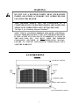
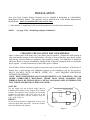
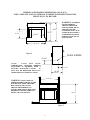
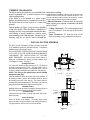
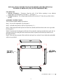
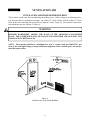
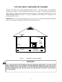
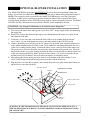
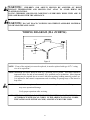
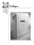
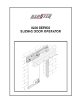
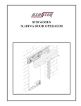
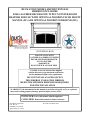
BUCK STOVE MODEL 42ZCBB VENTLESS
FIREBOX ENCLOSURE
FOR GAS-FIRED DECORATIVE TYPE UNVENTED ROOM
HEATERS FOR USE WITH OPTIONAL WOODEN FLUSH MOUNT
MANTEL (FF) AND OPTIONAL WOODEN SURROUND (WS)
(UNIVERSAL BOX)
FOR USE ONLY WITH
A LISTED GAS-FIRED UNVENTED
DECORATIVE ROOM HEATER
NOT TO EXCEED
40,000 BTU/H
DO NOT BUILD A WOOD FIRE
Carefully review the instructions supplied
with the decorative type unvented room heater
for the minimum fireplace size requirement.
DO NOT INSTALL AN APPLIANCE IN
THIS FIREBOX UNLESS THIS FIREBOX
MEETS THE MINIMUM DIMENSIONS REQUIRED
FOR THE INSTALLATION
WARNING: If the information in this manual is not followed exactly, a fire or explosion
may result causing property damage, personal injury or loss of life.
INSTALLER: Leave this manual with the appliance.
CONSUMER: Retain this manual for future reference.
New Buck Corporation
P.O. Box 69
8000 Hwy. 226 South
Spruce Pine, NC 28777
Revised: November 2004
TABLE OF CONTENTS
Safety Information and Warnings ....................................................................................... 3
Installation ........................................................................................................................... 5
Firebox and Framing Dimensions (ZC) (FF) ...................................................................... 6
Firebox Clearances (ZC) (FF) ............................................................................................. 7
Finishing Your Firebox ....................................................................................................... 8
Mantel Profiles For Zero Clearance .................................................................................... 9
Optional Wooden Flush Mount Mantel Front (FF)..…..…………………………………10
Optional Wooden Surround (WS)………………………………………………………...11
Producing Adequate Ventilation ....... ……………………………………………………13
Ventilation Air from Indoors ........................................................................................... 15
Ventilation Air from Outdoors ......................................................................................... 16
Optional Blower Installation ............................................................................................. 17
Wiring Diagram ................................................................................................................ 18
Replacement Parts ............................................................................................................. 19
Warranty ............................................................................................................................ 20
1
2
SAFETY INFORMATION
WARNINGS
IMPORTANT: READ THIS OWNER’S MANUAL CAREFULLY AND COMPLETELY
BEFORE TRYING TO ASSEMBLE, INSTALL, OPERATE, OR SERVICE THIS
APPLIANCE (FIREBOX ENCLOSURE).
Early signs of carbon monoxide poisoning resemble the flu, with headaches, dizziness, and/or nausea.
If you have these signs, the heater may not be working properly. Get fresh air at once! Have heater
serviced.
Some people-pregnant women, persons with heart or lung disease, anemia, those under the influence
of alcohol, and those at high altitudes-are more affected by carbon monoxide than others.
CAUTION: Strong drafts, such as a ceiling fan placed directly in front of the heater
(pulling from either direction) may create sooting. Sooting will discolor
walls.
1.
The installation must conform with local codes ,or in the absence of local codes, with the
National Fuel Gas Code, ANSI Z223.1/NFPA54.
*
2. This appliance may be installed in an After-Market Manufactured (Mobile) Home,
where not prohibited by state or local codes.
*
(After-Market: Completion of sale, not for purpose of resale from the manufacturer.)
3. “This heater shall not be installed in a confined space or unusually tight construction unless
provisions are provided for adequate combustion and ventilation air.”See Page 13, for
“Producing Adequate Ventilation”.
4.
Any safety screen or guard removed for servicing an appliance must be replaced prior to
operating the heater. This appliance (ventless firebox enclosure) is manufactured with
fireplace screens, and you must close any fireplace screens before operation of the decorative
type unvented room heater.
5. Do not use this heater for burning trash or cooking. Never place matches, paper, garbage, or any
other material on top of logs or into the flames.
6. “WARNING: Do not use a blower insert, heat exchanger insert or other accessory not approved for
use with this heater.”
7. “The fireplace canopy must not be modified or replaced with a canopy that may be provided with the
unvented decorative room heater.”
8. This universal box has been tested, listed, and certified to ANSI Z21. 91b-2004 Ventless Firebox
Enclosures for Gas-Fired Unvented Decorative Room Heaters.
3
WARNING
DO NOT USE A BLOWER INSERT, HEAT EXCHANGER
INSERT, OR OTHER ACCESSORY NOT APPROVED FOR
USE WITH THIS HEATER.
THIS HEATER SHALL NOT BE INSTALLED IN A
CONFINED SPACE UNLESS PROVISIONS ARE MADE FOR
ADEQUATE COMBUSTION AND VENTILATION AIR.
”See Page 13, for “Producing Adequate Ventilation”.
NOTE: THIS IS A VENTLESS FIREBOX ENCLOSURE (UNIVERSAL)
FOR GAS FIRED DECORATIVE TYPE UNVENTED ROOM HEATERS.
IT WILL ACCEPT ANY GAS LOGS UP TO 40,000 BTU’S AS LONG AS
MEET THE MINIMUM
THE LOGS WILL FIT.
YOU MUST
CLEARANCES SPECIFIED IN THE INSTRUCTION MANUAL.
FAILURE TO FOLLOW INSTALLATION INSTRUCTIONS WILL
VOID THE WARRANTY.
42 ZCBB FRONT
TOP FRONT PANELS
CANOPY
LEFT
SIDE
RIGHT
SIDE
SCREEN DOORS
FRONT SIDE PANELS
BOTTOM FRONT PANELS
4
INSTALLATION
Your New Buck Ventless Firebox Enclosure may be installed in Residential or *After-Market
Manufactured Mobile Homes. This appliance may be installed in an *After Market Manufactured
Mobile Home, where not prohibited by state or local codes.
* (After Market: Completion of sale, not for the purpose of resale from the manufacturer).
NOTE:
See page 13 for “Producing Adequate Ventilation”.
CHOOSING THE LOCATION FOR YOUR FIREBOX
Figure 1 shows some of the many ways your firebox may be installed. Consider the traffic pattern in
your room and the location of doors and windows. Moving air from ceiling fans, open doors, and hot
air grills may cause the flames to impinge the logs resulting in sooting. If a disturbance is found that
affects the flames, it must be eliminated by turning off the ceiling fan, closing the door, or closing the
hot air register. A corner location may be best where space is limited.
Your Ventless Firebox Enclosure weighs no more than some of your fine furniture. If the firebox is
located near a load bearing wall, additional supports to the foundation will not be necessary.
HEAVY FACINGS, SUCH AS BRICK, STONE, ETC., MAY REQUIRE ADDITIONAL
FOUNDATION SUPPORT.
NOTE: WHEN THE FIREBOX IS INSTALLED DIRECTLY ON CARPETING, TILE OR
OTHER COMBUSTIBLE MATERIALS, OTHER THAN WOOD FLOORING, THE
FIREBOX SHALL BE INSTALLED ON A METAL OR WOOD PANEL EXTENDING THE
FULL WIDTH AND DEPTH OF THE ENCLOSURE.
GAS LINE
The gas supply line and electrical supply must be
installed before framing in the fireplace by a licensed
installer. This appliance when installed, be electrically
grounded in accordance with local codes or, in the
absence of local codes, with the National Electrical
Code, ANSI \ NFPA 70.
PARTIAL ROOM PROJECTION
FULL ROOM PROJECTION
ROOM DIVIDER
DRAFTS
Do not locate the fireplace in high traffic areas or areas
exposed to high drafts and winds. Locate the fireplace
away from furniture and draperies.
CORNER
FLUSH
Figure 1
5
FIREBOX AND FRAMING DIMENSIONS (ZC) & (FF)
NOTE: SEE PAGE 10 IF AN OPTIONAL WOODEN FLUSH MOUNT MANTEL
FRONT (FF) IS TO BE USED.
WARNING: NOTCHING
38
1/8"
36-5/8"
35-5/8"
35 1/2"
18-15/16"
20
1/2"
33-1/8"
42
3/8"
OF THE FRAMING
AROUND THE STANDOFFS (SPACERS) OR ALTERATION OF THE
STANDOFFS CAN CAUSE
A FIRE OR MAY RESULT
IN PROPERTY DAMAGE,
PERSONAL INJURY, OR
LOSS OF LIFE.
46-3/8"
9/16”
37-5/16"
39
Figure 2
GAS LINE
8 1/16"
NOTE:
YOUR
NEW
BUCK
CORPORATION VENTLESS FIREBOX
ENCLOSURE IS EQUIPPED WITH A
FACTORY INSTALLED CANOPY.
IT
MAY NOT BE REPLACED WITH ANY
OTHER MANUFACTURER’S CANOPY.
10
1/4"
11 1/4"
19
3/8"
20 1/4"
45 11/16"
37-5/16"
WARNING: INSULATION OR
OTHER MATERIALS MUST NOT BE
PLACED AROUND OR THE FIREBOX, FILLING THE SPACES
AROUND THE FIREBOX CAN
CAUSE A FIRE OR MAY RESULT IN
PROPERTY DAMAGE, PERSONAL
INJURY, OR LOSS OF LIFE .
3836-5/8"
1/8"
Figure 2
6
FIREBOX CLEARANCES
The firebox may be placed directly on a combustible floor, firebox before installing.
against a combustible wall at marked clearances, or on a COMBUSTIBLE MATERIALS MUST NOT BE INSTALLED
OVER OR TOUCH ANY BLACK PAINTED SURFACE. DO
raised wooden platform.
NOT BLOCK HEAT CIRCULATING AIR OUTLETS. DOING
If the firebox is to be installed on a raised wooden
SO MAY RESULT IN POTENTIAL FIRE HAZARDS.
platform, the platform must be a continuous level surface.
1. Sidewall Clearances: Clearances from the side of the
The firebox must be secured in place so it cannot shift
firebox opening to any adjacent combustible wall should
positions.
not be less than 7".
Only the header (see Figure 3) may rest on the standoffs
2. Ceiling Clearances: The ceiling height should
on top of the firebox.. When the firebox is installed over
not be less than 42" from the top of the firebox
carpeting, vinyl tile, or any combustible material other than
opening.
wood flooring, it must be installed on a metal or wood
3. Front Clearances: 24” from the front of the
panel extending its full width and depth. Alternatively, the
firebox opening to any combustible materials.
carpeting, vinyl tile, etc. may be removed beneath the
INSTALLING THE FIREBOX
This list of specific instructions will help you make certain that
every installation operation is performed correctly. Complete the
installation steps in the sequence shown.
LOCAL BUILDING CODES SHOULD BE CONSULTED IN
ALL CASES AS TO THE PARTICULAR REQUIREMENTS
CONCERNING THE INSTALLATION OF FACTORY
BUILT FIREBOXES. Select the location for the firebox by
taking into consideration the factors previously outlined in the
“Choosing the Location.” See page 5.
Framing the Firebox
The width of the framed opening must be 46 9/16". The height of
the framed opening must be 38 1/8". The entire firebox can be
elevated above the floor to achieve a raised hearth effect. This can
be done by adding a small platform to achieve the desired height.
NOTE: The wiring for the optional blower must be installed
during the framing stage.
When the framing is inside, the outside wall will be insulated. If
the framing or chase is outside, thin insulation should be used in
the framing on the back, sides, and top. The bottom should be
insulated with a hard insulating board. This will prevent cold from
going into the chase through the firebox to the living space.
Install the Firebox
Install the firebox into the framed opening by placing it directly in
front of the opening and sliding it into the proper position.
Level the Firebox
Check the level of the firebox on the top edge of the firebox face.
Shim if necessary.
Secure the Firebox
Secure the firebox to the framing. The nailing flange on the
firebox will make securing the firebox to the frame quick and easy.
Use appropriate size nails or screws to secure the firebox.
37 9/16"
1/2"
TOP
VIEW
LEFT
20 1/4"
RIGHT
FRONT
46 9/16"
7"
SIDE VIEW
20 1/4"
38 1/8"
FRAMING
FRONT VIEW
HEADER
38 1/8"
46 9/16"
Figure 3
7
FINISHING YOUR FIREBOX
materials before using them on the face of the
firebox. Some of these products contain
combustible materials.
Combustible wall
coverings such as paneling or wallboard may
not overlap the black face of the firebox. The
space between the wall covering and the
firebox should be sealed with a heat resistant
material such as rock wool insulation or
mortar.
NOTE: An “L” shaped steel lintel must be
installed across the top of the firebox
opening where facing materials such as
brick or stone is used on the face of the
firebox. It acts as a support/firestop. It
should be attached to the face of the firebox
with screws and sealed to the firebox with a
heat-resistant sealer.
There is a wide variety of finishing material
available for your firebox from formal wall
treatments with marble and mantels, to rustic
wood paneling, stone or brick.
IT IS IMPORTANT THAT THE BLACK FACE
OF THE FIREBOX NOT BE COVERED WITH
ANY TYPE OF COMBUSTIBLE MATERIAL.
Non-combustible facing materials such as
marble, brick, or ceramic tile may overlap the
black face of the firebox up to the opening on
either side of the firebox. Seal all joints
between the black firebox face and the wall
covering with a heat-resistant material such as
rock wool insulation or mortar. Be sure to
use high temperature adhesive or mortar when
anchoring brick, stone, or tile to the face of
the firebox. Check to see whether man-made
brick and stone are made of non-combustible
CLEARANCES
3. Mantel Clearances: See Figure 5.
Non-combustible materials used in
this installation such as slate, tile,
marble, etc. must be at least 1/2"
thick.
4. Floor Clearances:
No
clearance is required if the
appliance is installed per these
instructions.
To ensure a safe installation, the following
must be carefully observed.
1. Sidewall Clearances: Clearances from
the side of the firebox opening to any
adjacent combustible wall should not be
less than 7". See Figure 4
2. Ceiling Clearances: The ceiling height
should not be less than 42" from the top
of the firebox opening.
FIGURE 4
7" MIN.
CLEARANCE
FROM FIREPLACE
OPENING TO SIDE WALL
42" MIN.
CLEARANCE
TO CEILING
SIDE WALL
LEFT
RIGHT
FRONT
24” FROM FRONT TO ANY COMBUSTIBLE MATERIAL
8
MANTEL PROFILES FOR VENTLESS FIREBOX ENCLOSURE
(UNIVERSAL BOX) ZERO CLEARANCE CABINET MUST BE FOLLOWED
A
COMBUSTIBLE
MATERIALS
3 1/2”
3/4”
3”
STANDOFF
B
42ZCBB
CANOPY
4”
FIGURE 5
MANTEL CLEARANCES
MANTEL WIDTH
(“A” inches)
MANTEL HEIGHT
(“B” inches above firebox opening)
6.0
8.0
10.0
12.0
14.0
14.0
14.0
16.0
9
INSTALLATION INSTRUCTIONS FOR MODEL 42ZCBB OPTIONAL
WOODEN FLUSH MOUNT MANTEL FRONT (FF) (KIT#PAKDM42ZCBBFF)
“NOTE: Follow the framing instructions on page(s) 6 & 7. With the exception of the placement
of the 42ZCBB in the framed opening . The 42ZCBB must be placed with the front surface of
the appliance 1-9/16” out from the finished wall. This well allow the FF to set flush with the
front of the 42ZCBB”.
CLEARANCES:
1. Sidewall Clearances: Clearances from the side of the firebox opening to any adjacent
combustible wall should not be less than 7". (See page 8, figure 4)
2. Ceiling Clearances: The ceiling height should not be less than 42" from the top of the firebox
opening.
INSTALLATION INSTRUCTIONS:
1. After removing the FF kit from its packaging follow any pre-installation instructions provided
with the kit.
2. Place the FF over the front of the 42ZCBB, centering the opening in the FF left to right with the
42ZCBB front.
3. Next you must secure the FF to the finished wall surface. You may use “L” brackets, screws or
finishing nails (not provided with the FF).
NOTE: If an unfinished FF kit is used, do not operate the appliance while finishing the wood or before the finish has dried properly.
TOP VIEW
REV.
DATE
BY
FINISHED WALL FACE
42ZCBB
66-1/8”
6”
42ZCBB & FF FRONTS
ARE FLUSH.
49-1/2”
42ZCBB
1-9/16”
59-1/8”
SIDE VIEW
FRONT VIEW
10
D
INSTALLATION INSTRUCTIONS FOR MODEL 42ZCBB OPTIONAL
WOODEN SURROUND (WS) (KIT# PAKDM42ZCBB)
CLEARANCES:
1. Sidewall Clearances: Clearances from the side of the firebox opening to any adjacent
combustible wall should not be less than 7". See Figure 4
2. Ceiling Clearances: The ceiling height should not be less than 42" from the top of the firebox
opening.
ASSEMBLY INSTRUCTIONS:
Tools Needed: Medium Phillips Screwdriver
Step 1: Lay out all components. (See diagram 1)
Step 2: Assemble end panels (A & B) to top front rail ( C ).
Step 3: Stand end panels and top front rail onto base (hearth) and fasten down with screws provided
(See diagram 1).
NOTE: Position back of end panels with back of base (hearth) centering assembly from each end. Install front screws first, then pull back towards the inside to square the surround up. Install screws
through back holes.
Step 4: Place top onto surround, flush with back and equal on each end. Secure both ends and middle
with screws provided.
CONTINUED
11
REAR VIEW
After assembling the WS you must insert the 42ZCBB. It is best to insert the 42ZCBB from the rear
of the WS, this gives you more area to hold the 42ZCBB and reduces the risk of scratching the surface of the front area of the base (hearth) area. Flush and center the 42ZCBB’s front in the WS.
You can attach the 42ZCBB to the WS with “L” brackets at the rear sides of the 42ZCBB (brackets
not provided).
42ZCBB
12
PRODUCING ADEQUATE VENTILATION
NOTICE: Information on provisions for adequate combustion and ventilation air are located in
the unvented room heater ‘s installation instructions. The unvented room heater’s instructions
must be followed exactly.
This section is used for residential installation or mobile home installation.
UNCONFINED SPACE:
An unconfined space has a minimum air volume of 50 cubic feet for each 1,000 BTU/Hr (4.8m3 per
Kw) input rating of all appliances in the space (Cubic feet equals Length x Width x Height of space).
Include adjoining rooms only if there are doorless passageways or ventilation grills between the
rooms.
CONFINED SPACE:
“The National Fuel Gas Code defines a confined space as a space whose volume is less than 50 cubic
feet per 1,000 BTU per hour (4.8m3 per KW) of the aggregate input rating of all appliances installed
in that space.
“WARNING: If the area in which the heater may be operated is smaller than that defined as an
unconfined space, provide adequate combustion and ventilation air by one of the methods
described in the National Fuel Gas Code, ANSI Z223.1, 1992, Section 5.3”
DETERMINING FRESH-AIR FLOW FOR
HEATER LOCATION
DETERMINE IF YOU HAVE A CONFINED OR UNCONFINED SPACE
Use this worksheet to determine if you have a confined or unconfined space.
SPACE: Include the room in which you will install heater plus adjoining rooms with doorless
passageways or ventilation grills between the rooms.
1. Determine the volume of the space (length x width x height).
Length x Width x Height= ________ cu.ft. (volume of space)
EXAMPLE:
20 ft. (length) x 16 ft. (width) x 8 ft. (ceiling height) =
2560 cu. ft. (volume of space)
If additional ventilation to adjoining room is supplied with grills or openings, add the volume of these
rooms to the total volume of space.
2. Divide the space volume by 50 cubic feet to determine the maximum BTU/Hr the space
can support.
________ (volume of space) / 50 cu. ft = (maximum BTU/Hr the space can support)
EXAMPLE: 2560 cu. ft. (volume of space) / 50 cu. ft. = 51.2 or
51200 (maximum BTU/Hr the space can support.)
13
3.
Add the BTU/Hr of all fuel burning appliances in the space.
Vent-Free Heater
_________________________BTU/Hr.
Gas Water Heater*
_________________________BTU/Hr.
Gas Furnace
_________________________BTU/Hr.
Vented Gas Heater
_________________________BTU/Hr.
Gas Fireplace Logs
_________________________BTU/Hr.
Other Gas Appliance*
+_________________________BTU/Hr.
Total
= _________________________BTU/Hr.
Example:
Gas water heater
Vent-free heater
Total
+
=
40000 BTU/Hr.
18000 BTU/Hr.
58000 BTU/Hr.
* Does not include direct-vent gas appliances. Direct-vent draws combustion
air from the outdoors and vents to the outdoors.
4.
Compare the maximum BTU/Hr the space can support with the actual amount
of BTU/Hr used.
_____________BTU/Hr (maximum the space can support)
_____________BTU/Hr (actual amount of BTU/Hr used)
Example:
51200 BTU/Hr (maximum the space can support)
58000 BTU/Hr (actual amount of BTU/Hr used)
The space in the above example is a confined space because the actual BTU/Hr used is more than the
maximum BTU/Hr the space can support. Additional fresh air must be provided. The following
options are available.
A. Rework worksheet, adding the space of an adjoining room. If the extra space provides an
unconfined space, remove door to adjoining room or add ventilation grills between rooms. See
“Ventilation Air From Inside Building”, page 15.
B. Vent room directly to the outdoors. See “Ventilation Air From Outdoors” page 16.
C. Install a lower BTU/Hr heater, if lower BTU/Hr size makes room unconfined.
If the actual BTU/Hr used is less than the maximum BTU/Hr the space can support, the space is
unconfined. You will need no additional fresh air ventilation.
WARNING
YOU MUST PROVIDE ADDITIONAL VENTILATION AIR IN A CONFINED SPACE
14
VENTILATION AIR
VENTILATION AIR FROM INSIDE BUILDING
This fresh air would come from an adjoining unconfined space. When venting to an adjoining space,
you must provide two permanent openings: one within 12" of the ceiling and one within 12" of the
floor on the wall connecting the two spaces (see Options 1 and 2, Figure 6). You can also remove door
into adjoining room (see Option 3, Figure 6).
WARNING
REWORK WORKSHEET, ADDING THE SPACE OF THE ADJOINING UNCONFINED
SPACE. THE COMBINED SPACES MUST HAVE ENOUGH FRESH AIR TO SUPPLY ALL
APPLIANCES IN BOTH SPACES.
NOTE: Each opening shall have a minimum free area of 1 square inch per 1000 BTU’s per
hour of the total input ratings of all gas utilization equipment in the confined space, but not less
than 100 square inches.
Figure 6
Ventilation Air From Inside Building
15
VENTILATION AIR FROM OUTDOORS
Provide extra fresh air by using ventilation grills or ducts. You must provide two permanent
openings: one within 12" of the ceiling and one within 12" of the floor. Connect these items directly
to the outdoors. These spaces include attics and crawl spaces. Follow the National Fuel Gas Code
NFPA 54/ANSI Z223.1, Section 4.3, “Air For Combustion and Ventilation” for required size of
ventilation grills or ducts.
IMPORTANT: Do not provide openings for inlet air into attic if attic has a thermostat-controlled
power vent. Heated air entering the attic will activate the power unit.
Ventilated Attic
Outlet Air
To Attic
Outlet Air
To
Crawl
Space
Inlet Air
Ventilated
Crawl Space
Inlet Air
Figure 7
Ventilation Air From Outdoors
WARNING
THIS HEATER MUST HAVE FRESH AIR FOR PROPER OPERATION. IF NOT, POOR
FUEL COMBUSTION COULD RESULT. READ THE FOLLOWING INSTRUCTIONS TO
ENSURE PROPER FRESH AIR FOR THIS AND OTHER FUEL-BURNING APPLIANCES
IN YOUR HOME.
16
OPTIONAL BLOWER INSTALLATION
The Model 42ZCBB has an optional MA ZCBB714 blower kit that can be purchased from your
dealer. You will need to follow these steps and the diagram below and the wiring diagram on page 15.
NOTE: The receptacle which is provided in the Model 42ZCBB must be wired into your home
(residence) in order to have electricity to operate the blower motor. If the receptacle hasn’t been
wired in during installation of the 42ZCBB you may need to contact a licensed electrician. The Model
42ZCBB also has a thermostat and wires and an ON/OFF switch standard on all units.
“WARNING: Any changes to this heater or its controls can be dangerous.”
A. First remove the burner base and logs. Be sure to turn “OFF” the gas supply before disconnecting
the supply line.
B. Remove the (10) ten hex-head self-piercing screws that hold down the motor cover plate on the
inner bottom of the unit.
C. Locate the (2) two wires that come down the back of the rear air channel from the thermostat .Connect (1) one of the thermostat wires to the top terminal on the ON/OFF switch.
D. Connect the black power cord wire to the 24" jumper wire provided, then attach the jumper wire
to the middle terminal on the ON/OFF switch. Next connect the remaining thermostat wire to (1)
of the wires coming from the motor. Connect the white power cord wire to the white motor wire.
The green power cord wire should be screwed to the motor bracket as the ground wire. Place the
blower motor in the cover plate opening. Position the blower motor into the air channel on the rear
of the unit centering the blower motor. It is best to leave about a 1/8" space between the blower
and the back of the air channel. This will reduce the chance of vibrating or noise.
E. After placing the blower motor you must secure it to the bottom of the unit with the (2) two
#10x1/2 Hex Washer Head self-piercing screws provided with the blower kit.
F. Plug the power cord into the receptacle, and reattach the motor cover plate to the inner bottom using the screws you removed earlier.
BLOWER MOTOR
SCREWS
THERMOSTAT
WIRES
NEW RE
DATE
SCREWS
THERMOSTAT
MOTOR COVER PLATE
POWER CORD
RECEPTACLE
ROMAX CONNECTOR
ON / OFF SWITCH
WIRES TO
SWITCH
WARNING: IF THE INFORMATION IN THIS MANUAL IS NOT FOLLOWED EXACTLY, A
FIRE OR EXPLOSION MAY RESULT CAUSING PROPERTY DAMAGE, PERSONAL INJURY
OR LOSS OF LIFE.
17
WARNING:
CHILDREN AND ADULTS SHOULD BE ALERTED OF HIGH
SURFACE TEMPERATURE AND SHOULD STAT AWAY TO AVOID BURNS OR
CLOTHING IGNITION.
YOUNG CHILDREN SHOULD BE CAREFULLY SUPERVISED WHEN THEY ARE IN
THE SAME ROOM WITH THE APPLIANCE.
WARNING: DO NOT PLACE CLOTHING OR OTHER FLAMMABLE MATERIAL
ON OR NEAR THE APPLIANCE.
WIRING DIAGRAM (MA ZCBB714)
REV.
DATE
BY
D IS C R IP T IO N
APRVD
BLACK
WHITE
Figure 8
NOTE: “If any of the original wire must be replaced, it must be replaced with type 105o C. rating
wire or its equivalent.”
NOTE: Installation and repair should be done by a qualified service person. This heater should be
inspected before use and at least annually by a qualified service technician. More frequent
cleaning may be required due to excessive lint from carpeting, bedding material, pet hair, etc.
It is imperative that control compartments and circulating air passageways of the heater be
kept clean.
Caution:
Label all wires prior to disconnection when servicing these controls. Wiring errors
may cause operational damage.
Verify proper operations after servicing.
NOTE: THE N.B.C. OPTIONAL FAN KIT MUST BE ELECTRICALLY GROUNDED IN
ACCORDANCE WITH LOCAL CODES. IN THE ABSENCE OF LOCAL CODES,
THE NATIONAL ELECTRICAL CODE, ANSI/NFPA 70 MUST BE USED.
18
REPLACEMENT PARTS
1. PULL SCREEN (2) PER UNIT
2. SCREEN RODS (2) PER UNIT
3. REAR REFRACTORY AND SIDE REFRACTORY 2 PIECES PER UNIT
6. CANOPY
7. DOOR KIT (PART# MAZCBBDOORS)
PARTS MAY BE OBTAINED THROUGH YOUR LOCAL NBC DEALER. IN
ABSENCE OF A DEALER, PLEASE CONTACT NEW BUCK CORPORATION AT
P.O. BOX 69, 8000 HWY 226 SOUTH, SPRUCE PINE, NC 28777.
OPTIONAL PARTS
DESCRIPTION
PART NUMBER
MOTOR
PE SBR084
ON/OFF SWITCH
PE RA911VB
POWER CORD
PE 400240
JUMPER WIRES
MA18GA18FF
19
NEW BUCK CORPORATION
We reserve the right to amend these specifications at any time without notice. The only warranty
applicable is our standard written warranty. We offer no other warranty, expressed or implied.
LIMITED WARRANTY
VENTLESS FIREBOX ENCLOSURE
New Buck warrants this product to be free from defects in materials and components for two (2) years
from the date of first purchase, provided that the product has been properly installed, operated, and
maintained in accordance with all applicable instructions. To make a claim under this warranty the Bill
of Sale or canceled check must be presented.
This warranty is extended only to the original retail purchaser and covers the cost of parts required to
restore the heater to proper condition. Warranty parts MUST be obtained through an authorized Buck
Stove dealer and/or New Buck, who will provide original factory replacement parts. Failure to use
original factory replacement parts voids this warranty. The heater must be installed by a qualified
installer in accordance with all local codes and instructions furnished with the unit.
Warranty does not apply to parts that are not in original condition, normal wear and tear, or parts that
fail or become damaged as a result of misuse, accidents, lack of proper maintenance or defects caused
by improper installation.
WARRANTY DOES NOT COVER:
-
Removal and re-installation cost
Labor costs for replacements or repairs
Transportation
Cost of service call to diagnose trouble
Painted surfaces
Damage or defect caused by improper installation, accident, misuse, abuse, or alteration
TO THE FULL EXTENT ALLOWED BY THE LAW OF THE JURISDICTION THAT GOVERNS
THE SALE OF THE PRODUCT, THIS EXPRESS WARRANTY EXCLUDES ANY AND ALL
OTHER EXPRESSED WARRANTIES AND LIMITS THE DURATION OF ANY AND ALL
WARRANTIES, INCLUDING WARRANTIES OF MERCHANTABILITY AND FITNESS FOR A
PARTICULAR PURPOSE TO ONE (1) YEAR FROM THE DATE OF FIRST PURCHASE. NEW
BUCK LIABILITY IS HEREBY LIMITED TO THE PURCHASE PRICE OF THE PRODUCT AND
NEW BUCK SHALL NOT BE LIABLE FOR ANY OTHER DAMAGES WHATSOEVER
INCLUDING INCIDENTAL OR CONSEQUENTIAL DAMAGES.
Some states do not allow a limitation on how long an implied warranty lasts or an exclusion or
limitation of incidental or consequential damages, so the above limitation on implied warranties, or
exclusion on damages may not apply to you.
This warranty gives you specific legal rights. Other rights may vary from state to state.
20