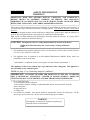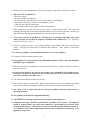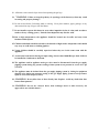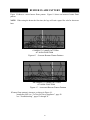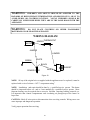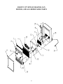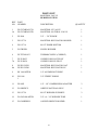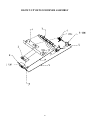
1
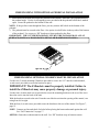
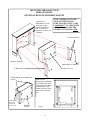
NEW BUCK CORPORATION
MODEL 1127B VENT-FREE GAS HEATER
WARNING: If the information in this manual is not followed exactly, a fire or
explosion may result causing property damage, personal injury or loss of life.
−
Do not store or use gasoline or other flammable vapors and liquids in the vicinity of this
or any other appliance.
WHAT TO DO IF YOU SMELL GAS
•
•
•
•
−
Do not try to light any appliance.
Do not touch any electrical switch; do not use any phone in your building.
Immediately call your gas supplier from a neighbor’s phone. Follow the gas supplier’s
instructions.
If you cannot reach your gas supplier, call the fire department.
Installation and service must be performed by a qualified installer, service agency or the
gas supplier.
This is an unvented gas-fired heater. It uses air (oxygen) from the room in which it is installed. Provisions for adequate combustion and ventilation air must be provided. Refer to
section “ Producing Adequate Ventilation” page 13.
This appliance may be installed in an aftermarket, permanently located, manufactured
(mobile) home, where not prohibited by local codes.
This appliance is only for use with the type of gas indicated on the rating plate. This appliance is not convertible for use with other gases.
INSTALLER: Leave this manual with the appliance.
CONSUMER: Retain this manual for future reference.
Manufacturer: NEW BUCK CORPORATION
P.O. Box 69
8000 Highway 226 South
Spruce Pine, NC 28777
March 2005
This appliance is intended for supplemental heating.
TABLE OF CONTENTS
Safety Information and Warnings ........................................................................... 3
Product Identification.............................................................................................. 6
Product Features...................................................................................................... 7
Unpacking ............................................................................................................... 7
Installation............................................................................................................... 9
Producing Adequate Ventilation (Fresh Air for Combustion and Ventilation) .... 13
Gas Connection ..................................................................................................... 17
Connecting to Gas Supply .................................................................................... 18
Gas Pressure Check………………………………………………………………20
Log Placement……………………………………………………………………21
Lighting Instructions ............................................................................................ 22
Flame Check .................................................................................................... 26-27
Inspecting Pilot ................................................................................................ 26-27
Burner Flame Pattern ....................................................................................... 26-27
Wiring Diagram .................................................................................................... 28
Cleaning and Maintenance .................................................................................... 30
Troubleshooting .................................................................................................... 32
Technical Service .................................................................................................. 29
Parts List & Blown up View ............................................................................ 36-40
Warranty ............................................................................................................... 41
1
2
SAFETY INFORMATION
WARNINGS
IMPORTANT: READ THIS OWNER’S MANUAL CAREFULLY AND COMPLETELY
BEFORE TRYING TO ASSEMBLE, OPERATE, OR SERVICE THIS APPLIANCE.
IMPROPER USE OF THESE LOGS CAN CAUSE SERIOUS INJURY OR DEATH FROM
BURNS, FIRE, EXPLOSION, AND CARBON MONOXIDE POISONING.
Early signs of carbon monoxide poisoning resemble the flu, with headaches, dizziness, and/or nausea. If
you have these signs, the heater may not be working properly. Get fresh air at once! Have burner
serviced.
Some people-pregnant women, persons with heart or lung disease, anemia, those under the influence of
alcohol, those at high altitudes-are more affected by carbon monoxide than others.
Make certain you understand and read all Warnings. Keep this manual for reference. It is your guide to
safe and proper operation of this heater and logs.
CAUTION:
Strong drafts, such as a ceiling fan placed directly in front of the heater
(pulling from either direction) may create sooting. Sooting will discolor
walls.
1. The installation must conform with local codes, or in the absence of local codes, with the National
Fuel Gas Code, ANSI Z223.1/NFPA54.
2. This appliance may be installed in an After-Market* Manufactured (Mobile) Home, where not
prohibited by state or local codes.
*
(After-Market: Completion of sale, not for purpose of resale from the manufacturer.)
This appliance is only for use with the type of gas indicated on the rating plate. This appliance is
not convertible for use with other gases.
NOTE: See Page 13, for “Producing Adequate Ventilation”.
IMPORTANT: VENT-FREE HEATERS ADD MOISTURE TO THE AIR. ALTHOUGH
THIS IS BENEFICIAL, INSTALLING HEATER IN ROOMS WITHOUT ADEQUATE
VENTILATION MAY CAUSE MILDEW TO FORM FROM TOO MUCH MOISTURE.
3. Never install this heater:
- in a recreational vehicle, bathroom.
- where curtains, furniture, clothing, or other flammable objects are less than 24" from the
front of the heater
-in high traffic areas
- in windy areas
4. Two models are available. One specific model for propane(LP), and one for natural gas. Use the
correct type gas for your home. Do not convert from one gas type to another.
WARNING
This appliance is equipped for (natural or propane) gas .
Field conversion is not permitted.
3
5. If this heater is used with propane gas, do not place propane supply tank (s) inside any structure.
6.
What To Do IF You Smell Gas:
Shut off gas supply.
- Do not try to light any appliance.
- Do not touch any electrical switch; do not use any phone in your building.
- Immediately call your gas supplier from a neighbor’s phone.
Follow the gas supplier’s instructions.
- If you cannot reach your gas supplier, call the fire department.
7. When operated for the first time, the logs may emit a “paper burning” smell. This smell will
gradually diminish and will be totally eliminated after the first few hours of operation. Run the gas
logs with the flue damper open during this time. Do not use blower at this time.
8. “This heater shall not be installed in a confined space or unusually tight tight construction
unless provisions are provided for adequate combustion and ventilation air.” See “Producing
Adequate Ventilation”, page 13.
9. Surface of gas logs becomes very hot when operating. Keep children and adults away from hot
surface. Gas logs will remain hot for sometime after shutdown. Allow surface to cool before
touching.
10. Do not place clothing or other flammable material on or near the appliance.
11. If equipped, fresh air damper must be closed.
12. Keep appliance area clean and free from combustible materials, gasoline, and other flammable
flammable vapors and liquids. .
13. If burner shuts off, do not relight until you provide fresh outside air. If burner continues to shut off,
have unit serviced.
14. Do not use this heater if any part has been under water. Immediately call qualified service
technician to inspect the room heater and to replace any part of the control system and any
gas control which has been under water.
15. Turn off the heater and let cool before servicing.
16. These logs are made of bonded fiber. When removing logs and base, do not damage the bonded
material. If the material is damaged extensively, loose fiber dust could be emitted into the air.
17. Any safety screen or guard removed for servicing an appliance must be replaced prior to
operating the heater.
18. This appliance is intended for supplemental heating.
18. “WARNING: Any change to this heater or its controls can be dangerous.”
19. Installation and repairs should be performed by a qualified service person. The appliance
should be inspected before use and at least annually by a professional service person. More
frequent cleaning may be required due to excessive lint from carpeting, bedding material, etc.
It is imperative that control compartments, burners and circulating air passageways of the
appliance be kept clean.
4
20. All heater screens must be kept clean when operating the gas logs.
21. . ”WARNING: Failure to keep the primary air opening(s) of the burner(s) clean may result
in sooting and property damage.”
22. Do not use this heater for burning trash or cooking. Never place matches, paper, garbage, or any
other material on top of logs or into the flames.
23. Do not install or operate this heater in areas where impurities in the air exist (such as tobacco
smoke or heavy cooking grease). Particles from impurities may discolor walls.
24. Due to high temperatures, the appliance should be located out of traffic and away from
furniture and draperies.
25. Children and adults should be alerted to the hazards of high surface temperature and should
stay away to avoid burns or clothing ignition.
26. Young children should be carefully supervised when they are in the same room with the
appliance.
27. An unvented room heater having an input rating of more than 10,000 Btu per hour shall not
be installed in a bathroom or bedroom.
28. The appliance and its appliance main gas valve must be disconnected from the gas supply
pipping system during any pressure testing of that system at test pressure in excess of 1/2 psi
(3.5 kPa).
29. The appliance must be isolated from the gas supply pipping system by closing its equipment
shut-off valve during any pressure testing of the gas supply piping system at test pressures
equal to or less than 1/2 psi (3.5 kPa).
30. “WARNING: Do not allow fans to blow directly into fireplace. Avoid any drafts that alter
burner flame patterns.”
31. “WARNING: Do not use a blower insert, heat exchanger insert or other accessory not
approved for use with this heater.”
5
PRODUCT IDENTIFICATION
Figure 1
WARNING:Installation and repairs should be performed by a qualified service person. The
appliance should be inspected before use and at least annually by a professional service person.
More frequent cleaning may be required due to excessive lint from carpeting, bedding material, etc. It is imperative that control compartments, burners and circulating air passageways of
the appliance be kept clean.
6
PRODUCT FEATURES
SAFETY DEVICE
This heater has a pilot with an Oxygen Depletion Sensor Shutoff System (ODS). The ODS/
pilot is a required feature for vent-free room heaters. The ODS/pilot shuts off the heater if there
is not enough (oxygen) fresh air.
PIEZO IGNITION SYSTEM
This heater has a piezo igniter. This system requires no matches, batteries, or other sources to
light the heater.
This appliance is only for use with the type of gas indicated on the rating plate. This appliance
is not convertible for use with other gases.
Model 1127B P* or N*- (Sensing or Modulating Bulb) - This heater has a thermostat sensing
bulb. This bulb will modulate the flame up and down on the demand of the heat desired.
*P - Propane or LP (Liquid Petroleum)
*N - Natural gas
UNPACKING
1. Remove all protective packaging applied to heater for shipment.
2. Check heater for any shipping damage. If heater is damaged, promptly inform the dealer
from whom you made the purchase.
3. Lift heater by each bottom corner.
“WARNING: Any change to this heater or its controls can be dangerous.”
7
CAUTION
THIS HEATER CREATES WARM AIR CURRENTS. THESE CURRENTS MOVE HEAT
TO WALL SURFACES NEXT TO HEATER. DO NOT INSTALL HEATER WHERE
IMPURITIES IN THE AIR MAY EXIST.
MINIMUM CLEARANCES TO
COMBUSTIBLE CONSTRUCTION
NOTE: FOR GARAGE INSTALLATION
•
Heater Pilot and Burner must be at least 18" off the floor.
•
Locate heater AWAY FROM ANY MOVING VEHICLE.
•
Keep appliance area clear and free from combustible materials, gasoline and other
flammable vapors and liquids.
For convenience and efficiency, install heater:
in easy access locations
in coolest part of room
near an electrical outlet
Minimum Clearances are as follows:
42” from the top of the appliance to the ceiling. 5” from the right front corner of the appliance to an
adjacent side wall, and 5” from the left side of the appliance to an adjacent side wall. 7” from the
bottom of the appliance to the top surface of carpeting, tile or other combustible materials in the area
described. See figure 2 below.
∗
∗
∗
•
The installation must conform with local codes or, in the absence of local codes, with the
National Fuel Gas Code, ANSI Z223.1/NFPA 54.
Note: Front Corner of heater
to an adjacent sidewall with
or without CSA listed
optional wooden mantel.
t sur e
c
Fron
the applian
m
Fro of the ustible
b
e
fac y com
n
to a rial.
e
mat
24”
42"
5"
CAUTION: Do Not obstruct
air openings around appliance.
Improper operation will occur.
Left
Side
Right
Side
Fron
t
7"
Figure 2
8
INSTALLATION
NOTE: This heater may be installed three different ways:
1. Wall Mounted
2. Freestanding heater (with optional pedestal)
3. Freestanding (with optional wooden mantel)
WALL MOUNT INSTALLATION:
1. After determining the location for the heater, unfold the template provided and place the bottom
of the template a minimum of 7" from bottom of unit to floor.
NOTE: Be sure to level the template before punching the holes.
2. With the template in place and the four black dots centered on studs, punch the four centers
marked in the black dots with a sharp pointed object. Insert the four wood screws provided with
the unit into the four punched holes.
NOTE: Leave 5/8" of the screw
FINISHED WALL
projecting from the finished wall.
Figure 3
5/8" or 15.875 mm
For sheet rock walls, use wing nuts or anchor wings. Remove the wing nut from the bolt. Place a nut
and washer with the same thread and size on the bolt. Push the wing nut through the wall surface
allowing the wings to spread. Tighten the nut that you placed on the bolt, leaving the required 5/8"
between the back of the bolt head and the finished wall.
Sheet Rock
Washer
Stud Wall
Figure 4
Nut
Wing Nut
Toggle Bolt
5/8" or 15.875 mm
9
3. Lift heater by each bottom corner and place the round part of the tear drop punch out over each
screw head. Gently push down until the body of the screw is at the end of the slot.
NOTE: Make sure unit is level.
4. Now you are ready to hook up the gas line. The Model 1127 allows for a rear or bottom
connection for the gas line. See “Gas Connection” on page 17 for details.
CLEANING INFORMATION:
Cleaning is a vital part of the life of your stove. In order to properly clean the unit, remove the front.
To remove: use Phillips screwdriver to loosen four screws in the sides of the front. You will find that
the front is easily removed in one piece.
Next you must remove the log(s) from the burner base. Gently place your hands, one on each side of
the log(s) and lift upward. Do not apply to much force on the log(s), this may cause damage to the
fiber material.
Figure 5
A vacuum cleaner works well for removal of dust and debris from around the burner and logs. To
remove the burner, use a tool with an extension to loosen the screw in the base. The screw is located
between the log and the actual base. Simply slide the base out of the unit. NOTE: Do not use a pin or
any sharp object to clean the pilot.
NOTE: Any parts that are removed while cleaning must be replaced before operating the appliance.
Figure 6
10
FREESTANDING WITH OPTIONAL PEDESTAL INSTALLATION
1. Place heater on backside and center the pedestal on the bottom. Mark the 4 pre-punched holes in
the pedestal angle. Use the 4 self-tapping screws provided with the pedestal to drill the 4 marked
spots. Secure the pedestal to the bottom of the unit.
NOTE: If the gas line is run through the floor, you may want to drill a hole in the bottom of the
pedestal.
2. The pedestal must be secured to the floor. One option is to drill holes in the top side of the bottom
of the pedestal. Use screws or “Ell” brackets to fasten pedestal to the floor.
IMPORTANT: THE 1127 FREESTANDING UNIT MUST BE INSTALLED ON A FLAT
SURFACE (SUCH AS A WOOD PANEL, METAL OR HARDWOOD FLOORS.)
FREESTANDING OPTIONAL WOODEN MANTEL INSTALLATION
Use the two (2) metal mounting Z-Brackets provided to secure the 1127 into the wooden mantel,
wood screws provided to secure the brackets in place.
IMPORTANT! The Z-Brackets must be properly installed. Failure to
install the Z-Brackets may cause property damage or personal injury.
Use the four (4) sheet metal screws provided to secure the mounting brackets to the rear of the stove.
Insert the screws into the back of the unit.
With the brackets secured to the unit. From the rear slide the unit into the opening of the mantel, centering from left to right.
With the four (4) wood screws provided secure the brackets to the rear of the mantel. See Figure 7,
page 12.
NOTE: Connect gas line and check for leaks before placing the heater and mantel against the wall.
See “Gas Connection” on page 17.
OPTION: Fasten the wooden mantel to the wall. Use “Ell” brackets at top or bottom corners.
11
MOUNTING BRACKET VIEW
FREE-STANDING
OPTIONAL DELUXE FINISHED MANTEL
OPTIONAL “L”
BRACKETS (2) AND
SCREWS (2) PROVIDED WITH MANTEL, TO SECURE
MANTEL TO WALL IF
NEEDED.
NOTE: “MODEL 1127 TO BE
B
REV. DATE
USED WITH NEW BUCK DATE
CORP. MANTEL ONLY, PART
# PAKDM1127.” IF USED WITH
ANY OTHER MANTEL THE
WARRANTY WILL BE VOID.
WOOD SCREWS
REAR OF MANTEL
SHEET METAL SCREWS
Z BRACKETS
REAR OF STOVE
Z-BRACKET(S) PLACEMENT ON
STOVE
NOTE: FLUSH
BRACKET
WITH REAR
TOP OF UNIT.
REAR OF
STOVE
Z-BRACKETS
MOUNTED (SCREWED)
TO THE REAR OF THE
STOVE AND SECURED
(SCREWED) TO THE
INSIDE REAR OF THE
FRONT OF THE MANTEL.
Figure 7
12
PRODUCING ADEQUATE
VENTILATION
This section is for residential or manufactured (mobile) installation
“This heater shall not be installed in a confined space or unusually tight construction unless provisions are adequate combustion and ventilation air.”
The National Fuel Gas Code, ANSI Z223.1/NFPA 54 defines a confined space as a space
whose volume is less than 50 cubic feet per 1,000 BTU per hour (4.8m 3 per kw) of the
aggregate input rating of all appliances installed in that space and an unconfined space as a
space whose volume is not less than 50 cubic feet per 1,000 BTU per hour (4.8m 3 per kw) of
the aggregate input rating of all appliances installed in that space. Rooms communicating
directly with the space in which the appliances are installed, through openings not furnished
with doors, are considered a part of the unconfined space.
“WARNING: IF THE AREA IN WHICH THE HEATER MAY BE OPERATED IS
SMALLER THAN THAT DEFINED AS AN UNCONFINED SPACE OR IF THE
BUILDING IS OF UNUSUALLY TIGHT CONSTRUCTION, PROVIDE ADEQUATE
COMBUSTION AND VENTILATION AIR BY ONE OF THE METHODS DESCRIBED
IN THE NATIONAL FUEL GAS CODE, ANSI Z223.1/NFPA 54, SECTION 5.3 OR
APPLICABLE LOCAL CODES.”
Unusually tight construction is defined as construction where:
a) Walls and ceilings exposed to the outside atmosphere have a continuous water vapor retarder
with a rating of 1 perm (6 x 10-11 kg per pa-sec-m2) or less with openings gasketed or sealed;
b) Weather stripping has been added on openable windows and doors, and
c) Caulking or sealants are applied to areas such as joints around window and door frames,
between sole plates and floors, between wall-ceiling joints, between wall panels, at penetrations
for plumbing, electrical, and gas lines, and at other openings.
NOTE: SOME AREAS IN THE UNITED STATES HAVE HIGHER REQUIREMENTS
FOR CUBIC FEET PER 1000 BTU/ HOUR INPUT. (EX. CINCINNATI, OHIO CODES
REQUIRE 70 CUBIC FEET). CHECK YOUR LOCAL CODE BEFORE
INSTALLATION.
DETERMINING FRESH-AIR FLOW FOR
HEATER LOCATION
DETERMINE IF YOU HAVE A CONFINED OR UNCONFINED SPACE
Use this worksheet to determine if you have confined or unconfined space.
SPACE: Includes the room in which you will install heater plus adjoining rooms with
doorless passageways or ventilation grills between the rooms.
13
1. Determine the volume of the space (length x width x height).
Length x Width x Height =_________cu.ft.(volume of space)
EXAMPLE: 20 ft.(Length) x 16 ft.(Width) x 8 ft.(ceiling Height)=
2560 cu. ft. (volume of space)
If additional ventilation to adjoining room is supplied with grills or openings, add the
volume of these rooms to the total volume of the space.
2. Divide the space volume by 50 cubic feet to determine the maximum BTU/Hr the
space can support.
_________(volume of space)/50 cu. ft. =maximum BTU/Hr the space can support)
EXAMPLE: 2560 cu. ft. (volume of space /50 cu. Ft .= 51.2 or
51200 (maximum BTU/Hr the space can support)
3. Add the BTU/Hr of all fuel burning appliances in the space.
Vent-free heater
_______________BTU/Hr
Gas water heater*
_______________BTU/Hr
Gas furnace
_______________BTU/Hr
Vented gas heater
_______________BTU/Hr
Gas fireplace logs
_______________BTU/Hr
Other gas appliances*
+ _______________BTU/Hr
Total
= _______________BTU/Hr
Example: Gas water heater 40000 BTU/Hr
Vent-free heater + 18000 BTU/Hr
Total
= 58000 BTU/Hr
*Does not include direct-vent gas appliances. Direct-vent draws combustion air
from the outdoors and vents to the outdoors.
4. Compare the maximum BTU/Hr the space can support with the actual amount of BTU/
Hr used.
____________BTU/Hr (maximum the space can support)
____________BTU/Hr (actual amount of BTU/Hr used)
Example: 51200 BTU/Hr (maximum the space can support)
58000 BTU/Hr (actual amount of BTU/Hr used)
The space in the above example is a confined space because the actual BTU/Hr used is more
than the maximum BTU/Hr the space can support. You must provide additional fresh
air. Your options are as follows: A. Rework worksheet, adding the space of an adjoining
room. If the extra space provides an unconfined space, remove door to adjoining room or add
ventilation grills between rooms. See “Ventilation Air From Inside Building”, page 21.
B. Vent room directly to the outdoors. See “Ventilation Air From Outdoors”, page 22.
C. Install a lower BTU/Hr heater, if lower BTU/Hr size makes room unconfined.
If the actual BTU/Hr used is less than the maximum BTU/Hr the space can support, the
space is an unconfined space. You will need no additional fresh air ventilation.
WARNING:
YOU MUST PROVIDE ADDITIONAL VENTILATION AIR IN A
CONFINED SPACE
14
VENTILATION AIR
VENTILATION AIR FROM INSIDE BUILDING
This fresh air would come from an adjoining unconfined space. When venting to an adjoining
space, you must provide two permanent openings: one within 12" of the ceiling and one within
12" of the floor on the wall connecting the two spaces (see Options 1 and 2, Figure 8). You can
also remove door into adjoining room (see Option 3, in Figure 8).
WARNING
REWORK WORKSHEET, ADDING THE SPACE OF THE ADJOINING
UNCONFINED SPACE. THE COMBINED SPACES MUST HAVE ENOUGH FRESH
AIR TO SUPPLY ALL APPLIANCES IN BOTH SPACES.
NOTE: Each opening shall have a minimum free area of 1 square inch per 1000 BTU’s per
hour of the total input rating of all gas utilization equipment in the confined space, but not less
than 100 square inches.
Figure 8
15
WARNING
THIS APPLIANCE MUST HAVE FRESH AIR FOR PROPER OPERATION. IF NOT,
POOR FUEL COMBUSTION COULD RESULT.
READ THE FOLLOWING
INSTRUCTIONS TO ENSURE PROPER FRESH AIR FOR THIS AND OTHER FUELBURNING APPLIANCES IN YOUR HOME.
VENTILATION AIR FROM OUTDOORS
Provide extra fresh air by using ventilation grills or ducts. You must provide two permanent
openings: one within 12" of the ceiling and one within 12" of the floor. Connect these items
directly to the outdoors. These spaces include attics and crawl spaces. Follow the National
Fuel Gas Code NFPA 54/ANSI Z223.1, Section 5.3, “Air For Combustion and Ventilation”
for required size of ventilation grills or ducts.
IMPORTANT: Do not provide openings for inlet air into attic if attic has a thermostatcontrolled power vent. Heated air entering the attic will activate the power unit.
VENTILATED ATTIC
OUTLET AIR
TO ATTIC
OUTLET AIR
TO
CRAWL
SPACE
INLET AIR
VENTILATED
CRAWL SPACE
INLET AIR
Figure 9
16
WARNING:
ANY CHANGE TO THIS HEATER OR ITS CONTROLS CAN BE
DANGEROUS.
GAS CONNECTION
Check gas type. Use only the type of gas indicated on the valve rating plate. If the type of gas listed on
the plate is not your type of gas supply, DO NOT INSTALL. Contact your dealer for proper model.
Always use an external regulator for all LP heaters to reduce the supply tank pressure to a maximum of
13" W.C. This is in addition to the regulator furnished with the heater.
WARNING: CONNECTION DIRECTLY TO AN UNREGULATED LP TANK CAN CAUSE
AN EXPLOSION.
The normal gas connection is 3/8” N.P.T. made at the left side (facing the front of the appliance) of the
appliance. If a right side connection is desired, the connecting pipe may be led under the rear of the
burner base to terminate at the right side for connection to the inlet of the valve.
NOTE: The connecting pipe must be internally tinned copper tubing for use with natural gas. Test for
leaks using a solution of soap and water after completing the connection. DO NOT USE OPEN
FLAME.
WARNING: Installation and repairs should be performed by a qualified service person. The
appliance should be inspected before use and at least annually by a professional service person.
More frequent cleaning may be required due to excessive lint from carpeting, bedding material,
etc. It is imperative that control compartments, burners and circulating air passageways of the
appliance be kept clean.
17
CONNECTING TO A GAS SUPPLY
CAUTION: NEVER CONNECT HEATER DIRECTLY TO THE PROPANE SUPPLY. THIS
HEATER REQUIRES AN EXTERNAL REGULATOR (NOT SUPPLIED). INSTALL THE
EXTERNAL REGULATOR BETWEEN THE HEATER AND THE PROPANE SUPPLY.
The installer must supply the external regulator for liquid propane gas. The external regulator will
reduce incoming gas pressure. You must reduce incoming gas pressure to between 11" and 14" of
water. If incoming gas pressure is not reduced, heater regulator damage will occur. Install external
regulator with the vent pointing down.
You must also install a sediment trap. Locate the sediment trap where it is within reach for cleaning.
A sediment trap filters moisture and contaminates. This also helps to keep the heater controls clean. If
sediment trap is missing or installed wrong, your unit will not run properly.
Propane Supply Tank
Figure 10
External Regulator
Vent Pointing Down
18
CAUTION: Use only new black iron or steel pipe. Internally tinned copper tubing may
be used in certain areas. Check state and local codes. Use pipe of 1/2" or greater in
diameter to allow proper gas volume. If piping is too small, undue loss of pressure will
occur.
Installation must include manual shutoff valve and plugged 1/2" NPT tap. Locate NPT tap
within reach for test gauge hook-up. NPT tap must be upstream from unit.
Apply pipe joint sealant lightly to male threads. This will prevent excess sealant from going
into pipe. Excess sealant in pipe could result in clogged heater valves.
CAUTION: USE PIPE JOINT SEALANT THAT IS RESISTANT
TO LIQUID PETROLEUM (LP) GAS.
Figure 11
19
GAS PRESSURE CHECK
Check the inlet pressure to the burner to insure that it is as shown in the table below.
NOTE: The pressure check point is located on the right side of the valve facing burner.
The appliance and its appliance main gas valve must be disconnected from the gas supply
piping system during any pressure testing of that system at test pressures in excess of 1/2
psi (3.5kPa).
The appliance must be isolated from the gas supply piping system by closing its equipment
shut-off valve during any pressure testing of the gas supply piping system at test pressures
equal to or less than 1/2 psi (3.5 kPa).
MODEL
Gas
Maximum Heat Input
Gas Inlet Pressure:
Maximum
Minimum
Manifold Pressure
FP-BR10-ZC
Natural
10000
FP-BR10-ZC
Propane
10000
10.5 ins. W.C.
* 5 ins. W.C.
3.5 ins. W.C.
13 ins. W.C.
*11 ins. W.C.
9 ins. W.C.
NOTE: On initial installation it may be necessary to bleed out air in the gas lines. Do this by
holding the control knob and turning the knob to the pilot position for about 30 seconds.
To check the Regulator pressure, remove the pressure tag plug at the left side of the Regulator
facing the heater. The pressure should be checked with the heater burning and the control set
on high. After measuring the pressure, replace the pressure tap plug,ensuring that there are no
leaks.
* For the purpose of minimum input adjustment.
WARNING
This appliance is equipped for (natural or propane) gas.
Field conversion is not permitted.
Figure 12
20
LOG PLACEMENT FOR 1127
Logs are shipped secured in unit.
NOTE: When operated for the first time, logs may emit a “paper burning” smell. This
smell will gradually diminish and will be totally eliminated after the first few hours of
operation. Do not use the blower at this time.
Front View of Logs
WARNING
“FAILURE TO POSITION THE PARTS IN ACCORDANCE WITH THESE
DIAGRAMS OR FAILURE TO USE ONLY PARTS SPECIFICALLY APPROVED
WITH HEATER MAY RESULT IN PROPERTY DAMAGE OR PERSONAL INJURY.”
WARNING
“DO NOT ALLOW FANS TO BLOW DIRECTLY INTO THE FIREPLACE. AVOID
ANY DRAFTS THAT ALTER BURNER FLAME PATTERN.”
21
OPERATING INSTRUCTIONS
Before operating this appliance, proceed through the following checklist
.
1. Read and understand these instructions before operating this appliance.
2. Check that there no leaks. If you smell gas do not attempt to light this appliance.
LIGHTING INSTRUCTIONS
MODULATING VALVE(MAXITROL)
FOR YOUR SAFETY, READ BEFORE LIGHTING
WARNING
IF YOU DO NOT FOLLOW THESE INSTRUCTIONS EXACTLY, A FIRE OR EXPLOSION MAY RESULT CAUSING PROPERTY DAMAGE, PERSONAL INJURY
OR LOSS OF LIFE.
A.
This appliance has a pilot which must be lighted by hand. When lighting the pilot,
follow these instructions exactly.
B. BEFORE LIGHTING: Smell all around the appliance for gas. Be sure to smell next
to the floor because gas is heavier than air and will settle on the floor.
WHAT TO DO IF YOU SMELL GAS
* Do not try to light any appliance.
* Do not touch any electrical switch; do not use any phone in your building.
* Immediately call your gas supplier from a neighbor’s phone. Follow the gas
supplier’s instructions.
* If you cannot reach your gas supplier, call your local fire department.
C. Use only your hand to push in or turn the gas control knob. Never use tools. If the knob
will not push in or turn by hand, don’t try to repair it, call a qualified service technician.
Force or attempted repair may result in fire or explosion.
D. Do not use this appliance if any part has been under water. Immediately call a qualified
service technician to inspect the appliance and to replace any part of the control system
and any gas control which has been under water.
22
LIGHTING INSTRUCTIONS
1.
2.
3.
4.
5.
6.
STOP! Read the safety information on the previous page.
Make sure manual shutoff valve is fully closed.
Open access panel door, located in lower front center of base for access to control knobs.
Turn off all electric power to the appliance.
Set thermostat (flame control) to lowest setting.
Push in and turn control knob clockwise
to the “OFF” position.
PILOT
ON
4
IGNITE
OFF
MERTIK
6
5
MAXITROL
7
3
2
1
FLAME
CONTROL
CONTROL
KNOB
FIGURE 3
7. “Wait (5) five minutes to clear out any gas. Then smell for gas, including near the floor. If
you smell gas, STOP! Follow step “B” in the safety information on the previous page. If
you don’t smell gas, go to the next step.”
8. Find Pilot: follow the small metal tub from the right hand rear of the gas control valve.
The pilot is located behind the burner tub and in front of the rear log. Fully open the manual shut-off valve.
9. Turn control knob counterclockwise
to the “PILOT” position. Press in
control knob for (15) fifteen seconds (see figure 3).
10. With control knob pressed in, turn control knob clockwise
to IGNITE and
then immediately back to PILOT with the button still pressed in. This will light the pilot.
If needed, keep repeating this step until pilot lights.
11. Keep control knob pressed in for one (1) minute after lighting pilot. After (1) minute,
release the control knob. If pilot goes out, repeat steps 1 through 9.
• If the knob does not pop up when released, stop and immediately call your service technician or gas supplier.
• “If the pilot will not stay lit after several tries, turn the gas control knob to “OFF” and call
your service technician or gas supplier.”
12. Turn control knob counterclockwise
to “ON” position.
13. “Set thermostat (flame control) to desired setting. Turn clockwise
for “LOW”
and counterclockwise
for “HIGH”.
23
IGNITER ELECTRODE
THERMO-COUPLE
O.D.S
PILOT BURNER
PILOT
14. Close the access panel door.
15. “Turn on all electric power to the appliance.”
CAUTION
DO NOT TRY TO ADJUST HEATING LEVELS BY USING THE
MANUAL SHUTOFF VALVE.
TO TURN OFF GAS TO APPLIANCE
SHUTTING OFF UNIT:
Open access panel door, located in lower front center of base for access to control knobs.
Set thermostat (flame control) to lowest setting.
Turn control knob clockwise
to the full “OFF” position.
“Turn off all electrical power to the appliance if service is to be performed.”
Close access panel door.
SHUTTING OFF BURNER ONLY (pilot stays lit)
1. Open access panel door, located in lower front center of base for access to control knobs.
2. Turn control knob clockwise
to the “PILOT” position.
3. Close access panel door.
1.
2.
3.
4.
5.
CAUTION:
Hot while in operation. Do Not Touch. Keep children, clothing, furniture,
gasoline, and other liquids having flammable vapors away.
CAUTION: DO NOT TRY TO ADJUST HEATING LEVELS BY USING THE
MANUAL SHUTOFF VALVE.
WARNING:
Improper installation, adjustment, alteration, service or maintenance can
cause property damage, personal injury, or loss of life. Refer to owner’s information manual
provided with this appliance. Installation and service must be performed by a qualified
installer, service agency, or the gas supplier.
IMPORTANT:
Always operate the appliance at the completely “ON” or the completely
“OFF” positions. Never use the heater at a setting between these positions as this can result in
improper combustion and excessive carbon monoxide emissions.
24
THERMOSTAT CONTROL OPERATION
The thermostat control used on this heater differs from standard thermostats. Standard
thermostats simply turn the burner on and off. The thermostat used on this heater senses the
room temperature and adjusts the amount of gas flow to the burner. This will increase
or decrease the flame height. At times, the room may exceed the set temperature, which will
cause the burner to shut off. When room temperature drops below the thermostat setting,
the burner will cycle itself on again. The flame control knob can be set to any level between
2 and 7.
NOTE: The thermostat sensing bulb measures the temperature of air near the heater cabinet.
This may not always agree with room temperature ( depending on housing construction,
installation location , room size, open air temperature,etc.). Frequent use of your heater will
allow you to determine your personal comfort levels.
MANUAL LIGHTING PROCEDURE
1. If the pilot cannot be ignited with the ignitor on the control valve, it can be manually lit
with the use of a paper match and a lighter rod.
2. Place the match in the holder and light. With other hand, depress the control knob
counterclockwise
to PILOT.
3. Use rod to light match and ignite pilot. The pilot is located behind the burner tub and in
front of the rear log. Fully open the manual shut-off valve.
4. Continue to hold the control knob for an additional (1) one minute to ensure the pilot
is completely on.
• If the knob does not pop up when released, stop and immediately call your service technician or gas supplier.
• “If the pilot will not stay lit after several tries, turn the gas control knob to “OFF” and
call your service technician or gas supplier.”
5. Turn control knob counterclockwise
to “ON” position.
“Set thermostat (flame control) to desired setting. Turn clockwise
for “LOW”
and counterclockwise
for “HIGH”.
6. Close the access panel door.
7. “Turn on all electric power to the appliance.”
25
FLAME CHECK
A periodic check of the flames should be made. The pilot flame should always be present when the
unit is in operation. See Figure 17.
FLAME: Propane (LP) should produce a flame that is about 6" above the rear log. This flame should
be yellow.
Natural gas should produce a flame that is about 3" to 4" above rear log. This flame should be mostly
blue except for the top tips which should be yellow.
NATURAL PILOT
PROPANE PILOT
BURNER
Figure 17
26
BURNER FLAME PATTERN
Figure 18 shows a correct burner flame pattern. Figure 19 shows an incorrect burner flame
pattern.
NOTE: When using the heater the first time, the logs will emit a paper like odor for about one
hour.
CORRECT FLAME PATTERN
AT HIGH POSITION
Figure 18
15 - Correct Burner Flame Pattern
INCORRECT FLAME PATTERN
AT HIGH POSITION
Figure 19
16 - Incorrect Burner Flame Pattern
If burner flame pattern is incorrect, as shown in Figure 19:
*turn heater OFF (see “To Turn Off Gas to Appliance”, page 28.
*see “Troubleshooting”, pages 35 through 39.
27
WARNING:
CHILDREN AND ADULTS SHOULD BE ALERTED TO THE
HAZARDS OF HIGH SURFACE TEMPERATURE AND SHOULD STAY AWAY TO
AVOID BURNS OR CLOTHING IGNITION. YOUNG CHILDREN SHOULD BE
CAREFULLY SUPERVISED WHEN THEY ARE IN THE SAME ROOM WITH THE
APPLIANCE.
WARNING:
DO NOT PLACE CLOTHING OR OTHER FLAMMABLE
MATERIALS ON OR NEAR THE APPLIANCE.
WIRING DIAGRAM
MOTOR
THERMOSTAT
JUMPER
JUMPER
JUMPER
GREEN
WHITE
BLACK
RHEOST
BLACK
POWER CORD
Figure 10
NOTE: “If any of the original wire as supplied with the appliance must be replaced, it must be
replaced with a wire of at least a 105o C. temperature rating.”
NOTE: Installation and repair should be done by a qualified service person. This heater
should be inspected before use and at least annually by a qualified service person. More
frequent cleaning may be required due to excessive lint from carpeting, bedding material, etc.
It is imperative that control compartments and circulating air passageways of the heater be
kept clean.
CAUTION: Label all wires prior to disconnection when servicing controls. Wiring errors can
cause improper and dangerous operation.
Verify proper operation after servicing.
28
WARNING: ELECTRICAL GROUNDING INSTRUCTION:
THIS APPLIANCE
IS EQUIPPED WITH A THREE-PRONG (GROUNDING) PLUG FOR YOUR
PROTECTION AGAINST SHOCK HAZARD AND SHOULD BE PLUGGED
DIRECTLY INTO A PROPERLY GROUNDED THREE-PRONG RECEPTACLE.
NOTE: #PE A24001 Blower Motor
Rating: 120 volts/60MZ/0.54 Amps. 1 P.H.
Blower Motor is standard on all Model 1127B. See page 38 for blower motor location.
NOTE: For convenience, allow licensed electrician to properly install a grounded 3-plug
receptacle near the unit.
SERVICING
Repair and replacement work should only be performed by a qualified service technician.
Always shut off the gas supply and make sure heater is cool before beginning any service
operation. Check for gas leaks after servicing.
REPAIR PARTS
A parts list with exploded view follows. Always include correct name, part number, and model
number of the heater when ordering service parts. Please contact your local dealer or distributor
when ordering. If one is not available, you may contact:
New Buck Corporation
8000 Highway 226 South
Spruce Pine, NC 28777
828-765-6144
29
IMPORTANT SAFEGUARDS
Although your gas logs are very realistic in appearance, it is not a real burning fireplace and must not be
used for burning rejected material.
• To avoid irreparable damage to the heater or personal injury, matches, paper, garbage, or any other
material must not be placed or thrown on top of the logs or into the flames.
• To avoid personal injury, do not touch hot surfaces when the heater is operating.
• Close supervision is necessary when the heater is being operated near children.
WARNING:
THE LOGS ARE MANUFACTURED FROM
BONDED CERAMIC FIBER.
THIS IS A COMMONLY USED
MATERIAL IN INDUSTRY WORLDWIDE. IN THE EVENT THAT A
LOG SHOULD BE REMOVED, CARE SHOULD BE TAKEN NOT TO
DAMAGE THE BONDED MATERIAL.
INTENTIONAL MISUSE OR DELIBERATELY FRAGMENTING THE
MATERIAL COULD LEAD TO INHALING FIBERS AND BE
HAZARDOUS TO YOUR HEALTH.
THIS HEATER IS INTENDED FOR USE AS A GAS HEATER
FIREPLACE AS DESCRIBED IN THESE INSTRUCTIONS. IT SHOULD
NOT BE USED FOR ANY OTHER PURPOSE.
CLEANING
CAUTION: BEFORE CLEANING OR MOVING THESE LOGS OR
OTHER PARTS OF THE HEATER, BE SURE TO READ THE ABOVE
SECTIONS ON “IMPORTANT SAFEGUARDS.”
See page 10, figure 6 before cleaning. The appliance must be turned “OFF”
before cleaning inside the firebox (burn area), make sure the pilot is “OFF”
completely and the appliance has cooled.
• All cleaning should be carried out when the heater is cold. Limited cleaning is required
with normal use. Dusting the front of the base, the top of the piezo cover, or the control
knob panel may be required occasionally. Do not use cleaning fluids to clean the logs or
any other part of the heater.
• If the flames show unusual shapes or behavior, or if burner fails to ignite properly, the
burner holes may require cleaning. If this occurs, contact your nearest dealer to service the
heater.
• The heater can be cleaned by removing the logs. Lift the logs gently, as not to damage the
fiber pieces. The logs have been spot glued in place for shipping, use caution when
removing. Lift each log by holding it carefully at each end. Use a vacuum cleaner to
remove dust and loose particles from the base, logs and around the burner and ODS/Pilot.
Gloves are recommended to prevent fibers from breaking the skin. If skin is broken, clean
with soap and water.
WARNING: Failure to keep the primary air openings(s) of the burner(s) clean may result
in sooting and property damage.
30
TROUBLE-SHOOTING
WARNING
TURN OFF AND UNPLUG HEATER AND LET COOL BEFORE SERVICING. ONLY
A QUALIFIED SERVICE PERSON SHOULD SERVICE AND REPAIR HEATER.
CAUTION
NEVER USE A WIRE, NEEDLE, OR SIMILAR OBJECT TO CLEAN ODS/PILOT.
THIS CAN DAMAGE ODS/PILOT.
WARNING:Installation and repairs should be performed by a qualified
service person. The appliance should be inspected before use and at least
annually by a professional service person. More frequent cleaning may be
required due to excessive lint from carpeting, bedding material, etc. It is
imperative that control compartments, burners and circulating air
passageways of the appliance be kept clean.
See pages 32 through 35 for Trouble Shooting.
31
OBSERVED
PROBLEM
POSSIBLE
CAUSE
1. Igniter button is pressed. No 1. Igniter electrode positioned
spark at ODS/Pilot
incorrectly
2. Igniter electrode broken
3. Igniter electrode not
connected to igniter cable
4. Igniter cable pinched or wet
5. Piezo igniter nut is loose
6. Broken igniter cable
7. Bad piezo igniter
2. Igniter button is pressed 1. Gas supply turned off or
Spark at ODS/Pilot
manual shutoff valve is
No Ignition
closed
2. Control knob not in “PILOT”
position
3. Control knob not pressed in
while in “PILOT” position
4. Air in gas lines when installed
5. Depleted gas supply
6. ODS/Pilot is clogged
7. Gas regulator setting is not
correct
32
SOLUTION
1. Replace igniter
2. Replace igniter
3. Reconnect igniter cable
4. Free igniter cable if pinched
by any metal or tubing. Keep
igniter cable dry.
5. Tighten nut holding piezo
igniter to heater cabinet. Nut
is located inside heater
cabinet at top.
6. Replace igniter cable
7. Replace piezo igniter
1. Turn on gas supply or open
manual shutoff valve
2. Turn control knob to “PILOT”
position
3. Press in control knob while in
“PILOT” position.
4. Continue to hold down control
knob. Repeat igniting
operation until air is removed.
5. Contact local propane gas
company
6. Clean ODS/Pilot or replace
ODS/Pilot assembly
7. Replace gas regulator
POSSIBLE
PROBLEM
OBSERVED
PROBLEM
3. ODS/PILOT lights but flame 1. Control knob is not fully
pressed in
goes out when control knob
2. Control knob not pressed in
is released
long enough
3.
4.
5.
6.
7.
4. Burner does not light after
ODS/Pilot is lit
SOLUTION
1. Press control knob completely
2. After ODS/Pilot lights keep
control knob pressed 30
seconds
Safety interlock system has 3. Wait 1 minute for safety
been triggered (if equipped)
interlock system to reset.
Manual shutoff valve not
4. Fully open manual shutoff
fully open
valve
Thermocouple connection
5. Hand tighten until snug, then
loose at control valve.
tighten 1/4 turn
Pilot flame not touching
6. A) Contact local propane gas
thermocouple, which allows
company
thermocouple to cool,
B) Clean ODS/Pilot (See
causing pilot flame to go
“Cleaning and Maintenance”),
out. This problem can be
or replace ODS/Pilot
caused by one or both of the
assembly
following:
A) low gas pressure
B) dirty or partially
clogged ODS/Pilot
Control valve damaged
7. Replace valve control
1. Burner orifice is clogged
2. Inlet gas pressure is too low
33
1. Clean burner (see “Cleaning
and Maintenance”) or replace
burner orifice
2. Contact local propane gas
company
OBSERVED
PROBLEM
5. Delayed ignition of burner
POSSIBLE
CAUSE
1. Manifold pressure is too low
2. Burner orifice is clogged
6. Burner backfiring during
combustion
1. Burner orifice is clogged or
damaged
2. Burner damaged
3. Gas regulator defective
SOLUTION
1. Contact local propane gas
company
2. Clean burner (see “Cleaning
and Maintenance”) or replace
burner orifice
1. Clean burner (see “Cleaning
and Maintenance”) or replace
burner orifice
2. Replace burner
3. Replace gas regulator
7. Slight smoke or odor during 1. Residues from manufacturing
initial operation
process
1. Problem will stop after a few
hours of operation
8. Heater produces a whistling 1. Turning control knob to “HI”
noise when burner is lit
position when burner is cold
(if equipped with this type of
valve)
2. Air in gas line
1. Turn control knob to “LOW”
position and allow to warm
3. Air passageways on heater
blocked
4. Dirty or partially clogged
burner orifice
34
2. Operate burner until air is
removed from line. Call
local propane company to
check gas line.
3. Observe minimum
installation clearances
4. Clean burner or replace
orifice
WARNING
IF YOU SMELL GAS:
* SHUT OFF GAS SUPPLY
* DO NOT TRY TO LIGHT APPLIANCE
* DO NOT TOUCH ANY ELECTRICAL SWITCH; DO NOT USE ANY
PHONE IN YOUR BUILDING
* IMMEDIATELY CALL YOUR GAS SUPPLIER FROM A
NEIGHBOR’S PHONE. FOLLOW THE GAS SUPPLIER’S
INSTRUCTIONS.
* IF YOU CANNOT REACH YOUR GAS SUPPLIER, CALL THE FIRE
DEPARTMENT.
IMPORTANT: Operating heater where impurities in the air exist may create odors. Cleaning
supplies, paint, paint remover, cigarette smoke, cements and glues, new carpet or textiles, etc.
create fumes. These fumes may mix with combustion air and create odor.
OBSERVED
POSSIBLE
SOLUTION
PROBLEM
CAUSE
1. Heater produces a clinking/ 1. Metal expands while
1. This is common with most
ticking noise just after burner
heating or contracts while
heaters. If noise is
is lit or shut off
cooling.
excessive, contact a
qualified service person.
2. Heater produces unwanted 1. Heater burning vapors
1. Ventilate room. Stop using
odors
from paint, hairspray,
odor causing products
glues, etc. (See
while heater is running.
Important above)
2. Refill supply tank.
2. Low fuel supply
3. Locate and control all
3. Gas leak (See WARNING
leaks. See “Checking Gas
above)
Connections”.
3. Heater shuts off in use
(ODS operates)
1. Not enough fresh air is
available.
2. Low line pressure
3. ODS/Pilot is partially
clogged
4. Gas odor even when control 1. Gas leak (See
knob is in “OFF” position
WARNING, above).
2. Control valve defect
1. Open window/door for
ventilation
2. Contact local propane co.
3. Clean ODS/Pilot
1. Locate and correct all leaks
(see Checking Gas
Connections)
2. Replace control valve
5. Gas odor during combustion 1. Foreign matter between
1. Remove foreign matter
control valve and burner
from gas tubing
2. Gas leak (See WARNING 2. Locate and correct all leaks
above).
(see “Checking Gas
Connections”).
35
TECHNICAL SERVICE
MODEL 1127 - MODULATING VALVE
BTU(Variable)
Type Gas
Ignition
Pressure Regulator Setting
Inlet Gas Pressure (in. of water)*
Maximum
Minimum
Dimensions, Inches (HxWxD)
Heater
Weight (pounds)
Heater
Shipping
11000/27000
Propane (LP)
Piezo
9" W.C.
3.5" W.C.
14"
11"
10.5" W.C.
5.0" W.C.
22" x 20 - 1/8" x 7"
45 pounds
* For purposes of input adjustment
36
11000/27000
Natural
PARTS LIST
KEY NO.
PART NUMBER
DESCRIPTION
1
MF 112738
VENT ROD
3
2
PO 1127IM
BRASS TRIM
4
3
PO PNPSNH50JT
FRONT
1
4
MA 1127SC
FRONT SCREEN
1
5
P0 112706
INNER SHIELD CHROME
1
6
MF 112782
LOG HOLDER
2
7
A2-40-01
FAN MOTOR
1
8
PS 112724
MOTOR BRACE
1
9
PS 112740
SCREEN MOTOR COVER
1
10
PE KB9724
FAN SPEED CONTROL LABEL
1
11
PE BC204
RHEOSTAT
1
12
PE BC204A
RHEOSTAT KNOB
1
13
PE 400132
110 DEG. DISC THERMOSTAT
1
14
PE 30JUMPER
THERMO JUMPER WIRE
2
15
PE 400320
STRAIN RELIEF
1
16
PE 400240
POWER CORD
1
17
PO 22GAJ1712
BRASS COVER DOOR LOUVER
3
18
PO WALLMT
LOG SET
1
19
PH 101612PHPTEK
SCREW, #10 x 1/2" PAN
2
20
PH101634TEK
SCREW, #10 x 3/4" HEX
2
21
PH 103212HWSPS5
SCREW, #10 x 1/2" HEX
6
22
PH 6114DWPHILSC
DRYWALL SCREW, 6" x 1 1/2"
2
23
PO 112772
SWITCH HOLDER
1
24
PO TBURN
SINGLE BURNER
1
37
QUANTITY
BLOWN UP VIEW OF HEATER, FAN
MOTOR, AND ALL REMOVABLE PARTS
38
PARTS LIST
MAXITROL VALVE
BURNER SYSTEM
KEY PART
NO. NUMBER
DESCRIPTION
1
1A
PE GV30B5A2L7B
PE GV30B5A2N7B
MAXITROL LP VALVE
MAXITROL NATURAL VALVE
1
1
2
PE 4966
3/8" - 3/8" ELBOW
1
3
PS 112736
MAXITROL REGULATOR HOLDER
1
4
PS 112716
M1127 INNER BOTTOM
1
5
PO TBURN
SINGLE BURNER
1
6
PE TPT100/433
THERMOCOUPLE (COPRECI)
1
7
7A
PE 2150053
PE 2150054
COPRECI ODS NAT PILOT
COPRECI ODS LP PILOT
1
1
8
8A
PE RV12LF30
PE RV12LF90
MAXITROL REGULATOR-NAT
MAXITROL REGULATOR-LP
1
1
9
RF 14ALMTUB
1/4" ALUMINUM TUBING
1
10
PH 1166
1
3/8" STREET ELBOW
11
PE 6482
1/4" - 1/8" COMPRESSION ADAPTER
2
12
PO ORIFICE
ORIFICE NATURAL OR LP
1
13
PS 112726
M1127 BURNER SUPPORTS
2
14
PO 38634ALMTUB
3/8" x 6 - 3/4" BURNER TUBE
1
15
PO 54ORFHLD
ANGLED ORIFICE HOLDER
1
39
QUANTITY
BLOWN UP VIEW OF BURNER ASSEMBLY
40
NEW BUCK CORPORATION
We reserve the right to amend these specifications at any time without notice. The only warranty
applicable is our standard written warranty. We offer no other warranty, expressed or implied.
LIMITED WARRANTY
ON VENT-FREE GAS LOG HEATER
New Buck warrants this product to be free from defects in materials and components for two (2)
years from the date of first purchase, provided that the product has been properly installed,
operated, and maintained in accordance with all applicable instructions. To make a claim under
this warranty the Bill of Sale or canceled check must be presented.
This warranty is extended only to the original retail purchaser and covers the cost of parts required
to restore the heater to proper condition. Warranty parts MUST be obtained through an authorized
Buck Stove dealer and/or New Buck, who will provide original factory replacement parts. Failure
to use original factory replacement parts voids this warranty. The heater must be installed by a
qualified installer in accordance with all local codes and instructions furnished with the unit.
Warranty does not apply to parts that are not in original condition, normal wear and tear, or parts
that fail or become damaged as a result of misuse, accidents, lack of proper maintenance or defects
caused by improper installation.
WARRANTY DOES NOT COVER:
-
Removal and re-installation cost
Labor costs for replacements or repairs
Transportation
Cost of service call to diagnose problem
Painted surfaces
Damage or defect caused by improper installation, accident, misuse, abuse, or alteration
TO THE FULL EXTENT ALLOWED BY THE LAW OF THE JURISDICTION THAT
GOVERNS THE SALE OF THE PRODUCT, THIS EXPRESS WARRANTY EXCLUDES ANY
AND ALL OTHER EXPRESSED WARRANTIES AND LIMITS THE DURATION OF ANY
AND ALL WARRANTIES, INCLUDING WARRANTIES OF MERCHANTABILITY AND
FITNESS FOR A PARTICULAR PURPOSE TO ONE (1) YEAR FROM THE DATE OF FIRST
PURCHASE. NEW BUCK LIABILITY IS HEREBY LIMITED TO THE PURCHASE PRICE
OF THE PRODUCT AND NEW BUCK SHALL NOT BE LIABLE FOR ANY OTHER
DAMAGES WHATSOEVER INCLUDING INCIDENTAL OR CONSEQUENTIAL DAMAGES.
Some states do not allow a limitation on how long an implied warranty lasts or an exclusion or
limitation of incidental or consequential damages, so the above limitation on implied warranties, or
exclusion on damages may not apply to you.
This warranty gives you specific legal rights. Other rights may vary from state to state.
41