1
User’s Guide
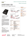
SFMFF4040-100
Optical Line Converter for
Small Form Factor Pluggable (SFP)
Transceiver Modules
The Transition Networks SFMFF4040-100 optical line
converter is designed to accommodate two (2) small
form factor pluggable (SFP) transceiver modules.
The following SFP transceiver modules are compatible with the SFMFF4040-100 converter
and are available from Transition Networks (sold separately).
Port 1
empty
Port 2
empty
SFMFF4040-100
Part Number
Description
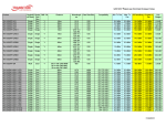
TN-SFP-SX
LC, 1000Base-SX, 850 nm multimode, 220-500 mm (720-1640 ft)
TN-SFP-LX1
LC, 1000Base-LX, 1310 nm single mode, 10 km (6.2 miles), DMI
TN-SFP-LX3
LC, 1000Base-LX, 1310 nm single mode, 30 km (18.8 miles), DMI
TN-SFP-LX5
LC, 1000Base-LX, 1550 nm single mode, 50 km (31.2 miles), DMI
TN-SFP-LX8
LC, 1000Base-LX, 1550 nm single mode, 80 km (50.0 miles), DMI
TN-SFP-LX12
LC, 1000Base-LX, 1550 nm single mode, 120 km (74.56 miles)
DMI
TN-SFP-OC3M
TN-SFP-OC3S
TN-SFP-OC12M
TN-SFP-OC12S
TN-SFP-FC2XM
TN-SFP-FC2XS2
TN-SFP-FC2XS15
TN-SFP-FC2XS40
LC, 100Base-FX/OC-3 SFP 1300 nm multimode 2km (1.2 miles),
DMI
LC, 100Base-FX/OC-3 SFP 1310 nm single mode 20km (12.4miles),
DMI
LC, OC-12/STM-4 SFP 1300 nm multimode 1 km (0.6 miles),
DMI
LC, OC-12/STM-4 SFP 1310 nm single mode 20 km (12.4 miles),
DMI
LC, 2x/1x/OC-48/STM-16/1000Base-SX, 850 nm multimode, DMI,
150 m (492 ft)* on 62.5/125 µm fiber,
300 m (984ft)* on 50/125 µm fiber
LC, 2x/1x/OC-48/STM-16/1000Base-LX, 1310 nm single mode, 2
km (1.2 miles), DMI
C, 2x/1x/OC-48/STM-16/1000Base-LX, 1310 nm single mode, 15
km (9.3 miles), DMI
LC, 2x/1x/OC-48/STM-16/1000Base-LX, 1310 nm single mode, 40
km (24.9 miles), DMI
SFMFF4040-100
Optical line converters -- continued
*Typical maximum cable distance. Actual distance is dependent upon the physical
characteristics of the network.
NOTE: Third-party Multi-Source Agreement (MSA) compliant Small Form Factor
Pluggables (SFPs) can be used in the SFMFF4040-100.
Installation -- continued
Remove SFP Transceiver Modules
To remove a SFP transceiver module from the SFMFF4040-100 converter:
1.
Swing the handle on the SFP transceiver to the “out” position.
2.
Carefully pull the module outward until it separates from the converter.
With any two of Transition Networks SFP transceiver modules installed, the
SFMFF4040-100 converter can perform the following mode and wavelength line
conversions.
Mode conversions:
• multimode to multimode
• multimode to single mode
• single mode to single mode
Wavelength line conversions:
• 850 nm to 850 nm
• 850 nm to 1310 nm
• 1310 nm to 850 nm
• 1310 nm to 1310 nm
• 1550 nm to 850 nm
• 1550 nm to 1310 nm
• CWDM (coarse wavelength division multiplexing)
• DWDM (dense wavelength division multiplexing)
• 850 nm to 1550 nm
• 1310 nm to 1550 nm
• 1550 nm to 1550 nm
2.
1.
Power the SFMFF4040-100
AC:
Installation
Install SFP Transceiver Modules
To install SFP transceiver modules into the SFMFF4040-100 converter:
1.
Position the SFP transceiver module at either installation slot, with the
label facing up.
2.
Carefully slide the module into the slot, aligning it with the internal
installation guides.
3.
Ensure that the module is firmly seated against the internal mating
connector.
4.
Repeat steps 1 - 3 to install a second module in the remaining slot.
1.
Connect the barrel connector, on the power adapter, to the power port
on the converter (on the back of the converter).
2.
Connect the power adapter plug to AC power.
3.
Verify that the converter is powered by observing the illuminated LED
power indicator light.
DC:
Consult the user’s guide for the Transition Networks SPS1872-xx DC external
power supply for powering the converter.
installation
slots
SFP transceiver
modules
2
24-hour Technical Support: 1-800-260-1312 -- International: 00-1-952-941-7600
[email protected] -- Click the “Transition Now” link for a live Web chat.
3
SFMFF4040-100
Operation
Technical Specifications -- continued
Status LEDs
The SFMFF4040-100 optical line converter is designed to operate without user
intervention. Use the status LEDs to view the operation of the converter in the
network.
PWR (Power)
On = Connection to external power.
LK1
(Fiber Link - Port 1)
On = Fiber port 1 is receiving a signal.
LK2
(Fiber Link - Port 2)
On = Fiber port 2 is receiving a signal.
Environment
Tmra*:
Storage Temp:
Humidity:
Altitude:
Warranty
Lifetime
-10° to 60°C (14° to 185°F)
-40° to 85°C (14° to 185°F)
5 to 95%, non condensing
0 to 10,000 feet
The information in this user’s guide is subject to change. For the most up-to-date
information on the SFMFF4040-100 optical line converter, view the user’s guide
on-line at: www.transition.com.
LK2
Port 1
Port 2
The chassis version of the media converter is CFMFF4040-100. For more
information, see the CFMFF4040-100 user’s guide on-line at:
www.transition.com.
Link Pass-Through
The Link Pass-Through feature allows the media converter to monitor both
fiber RX (receive) ports for loss of signal. In the event of an RX signal loss (1),
the media converter will automatically disable the TX (transmit) signal (2),
thus, “passing through” the link loss (3). The far-end device is automatically
notified of the link loss (4), which prevents the loss of valuable data
unknowingly transmitted over an invalid link.
media converter A
disables the fiber TX link
Near-End
Device
1
Media
Converter A
2
media converter B
loses the fiber RX link
3
Media
Converter B
original fault
on the fiber link
4
Far-End
Device
media converter B
disables the fiber link
Note: Link losses will be automatically repaired by the converters.
Technical Specifications
For use with Transition Networks model SFMFF4040-100 or equivalent.
Standards
4
12VDC, 0.5 Amp (North America)
12VDC, 0.41 Amp (Europe, Japan, Latin America)
12VDC, 1.25 Amp (UK, Australia, New Zealand, South Africa)
*Manufacturer’s rated ambient temperature.
PWR
LK1
Power Supply
MSA (Multi-Source Agreement) compliant SFP (Small Form
Factor Pluggables)
Dimensions
3.25 x 4.7 x 1.0" (83 x 121 x 25 mm)
Weight
10 oz. (283 g) approximate
Power
Consumption
2.0 Watts (with two (2) Transition Networks SFPs installed.)
(Power consumption depends on the type of SFPs installed.)
24-hour Technical Support: 1-800-260-1312 -- International: 00-1-952-941-7600
For the most up-to-date information on the TN-SFP-xxx transceiver modules, see
the user’s guide on-line at: www.transition.com.
Product is certified by the manufacturer to comply with DHHS Rule 21/CFR,
Subchapter J applicable at the date of manufacture.
WARNING: Visible and invisible laser radiation when open. Do not stare into
beam or view directly with optical instruments. Failure to observe this warning
could result damage to your eyes or blindness.
WARNING: Use of controls, adjustments or the performance of procedures
other than those specified herein could result in hazardous radiation exposure.
The fiber optic transmitters on this device meet Class I Laser safety requirements
per IEC-825/CDRH standards and comply with 21 CFR1040.10 and
21CFR1040.11.
Optional Accessories
Part Number
SPS-1872-SA
Description
Optional External Power Supply; 18-72VDC Stand-Alone;
Output: 12.6VDC, 1.0 A
SPS-1872-PS
Optional External Power Supply; 18-72VDC Piggy-Back;
Output: 12.6VDC, 1.0 A
12-Slot media converter Rack (includes universal internal power
supply) 17 x 15 x 5 in. (432 x 381 x 127 mm)
Optional Wall Mount Bracket; 4.0 in. (102 mm)
Optional Vertical Mount Bracket; 5.0 in. (127 mm)
Optional DIN Rail Mount Bracket; 5.0 in. (127 mm)
Optional DIN Rail Mount Bracket (flat); 3.3in. (84 mm)
E-MCR-04
WMBL
WMBV
WMBD
WMBD-F
[email protected] -- Click the “Transition Now” link for a live Web chat.
5
SFMFF4040-100
Troubleshooting
If the SFMFF4040-100 converter fails, isolate and correct the failure by
determining the answers to the following questions and taking the indicated
action:
1.
Is the PWR (power) LED illuminated?
NO
•
Ensure that the power adapter is the proper type of voltage and cycle
frequency for the outlet (See “Power Supply” on page 5.)
Ensure the power adapter is properly installed in the converter and in
the grounded outlet.
Contact Technical Support: US/Canada: 1-800-260-1312,
International: 00-1-952-941-7600.
•
•
YES
•
2.
Proceed to step 2.
Are both LK1 & LK2 LEDs (fiber link for ports 1 & 2) illuminated?
NO
•
Ensure both SFP transceiver modules are properly inserted in the
converter.
Check the fiber cables for proper connection.
Verify that the TX and RX cables on the media converter are
connected to the RX and TX ports, respectively, on the other device.
Contact Technical Support: US/Canada: 1-800-260-1312,
International: 00-1-952-941-7600.
•
•
•
YES
•
3.
Proceed to step 3.
Is the LK1 LED (fiber link 1) flashing?
NO
•
•
If there is no network activity on port 1, proceed to step 4.
If there is network activity on port 1, disconnect and reconnect the
fiber cables to restart the initialization process.
Contact Technical Support: US/Canada: 1-800-260-1312,
International: 00-1-952-941-7600.
•
YES
•
4
Technical support
Technical support is available 24 hours a day.
US and Canada:
1-800-260-1312
International:
00-1-952-941-7600
Transition now
Chat live via the Web with Transition Networks Technical Support.
Log onto www.transition.com and click the Transition Now link.
Web-based seminars
Transition Networks provides seminars via live web-based training.
Log onto www.transition.com and click the Learning Center link.
E-Mail
Ask a question anytime by sending an e-mail to our technical support staff.
[email protected]
Address
Transition Networks
6475 City West Parkway
Minneapolis, MN 55344, U.S.A.
telephone:
952-941-7600
toll free:
800-526-9267
fax:
952-941-2322
Declaration of Conformity
Name of Mfg:
Transition Networks
6475 City West Parkway, Minneapolis MN 55344 U.S.A.
Model:
SFMFF4040-100 SFP Optical Line Converter
Part Number:
SFMFF4040-100
Regulation:
EMC Directive 89/336/EEC
Purpose: To declare that the SFMFF4040-100 to which this declaration refers is
in conformity with the following standards.
EN 55022:1998 Class A; EN 55024: 1998+A1+A13164:2002; FCC Part 15 subpart B;
21CFR subpart J
I, the undersigned, hereby declare that the equipment specified above conforms to the above
Directive(s) and Standard(s).
June 6, 2006_____
Stephen Anderson, Vice-President of Engineering
Date
Proceed to step 4.
Is the LK2 LED (fiber link 2) flashing?
NO
•
•
•
6
Contact Us
If there is no network activity on port 2, contact technical support.
If there is network activity on port 2, disconnect and reconnect the
fiber cables to restart the initialization process.
Contact Technical Support: US/Canada: 1-800-260-1312,
International: 00-1-952-941-7600.
24-hour Technical Support: 1-800-260-1312 -- International: 00-1-952-941-7600
[email protected] -- Click the “Transition Now” link for a live Web chat.
7
Compliance Information
CISPR22/EN55022 Class A + EN55024; CE Mark
FCC regulations
This equipment has been tested and found to comply with the limits for a Class A digital
device, pursuant to part 15 of the FCC rules. These limits are designed to provide reasonable
protection against harmful interference when the equipment is operated in a commercial
environment. This equipment generates, uses, and can radiate radio frequency energy and, if
not installed and used in accordance with the instruction manual, may cause harmful
interference to radio communications. Operation of this equipment in a residential area is
likely to cause harmful interference, in which case the user will be required to correct the
interference at the user's own expense.
Canadian regulations
This digital apparatus does not exceed the Class A limits for radio noise for digital apparatus
set out on the radio interference regulations of the Canadian Department of Communications.
Le présent appareil numérique n'émet pas de bruits radioélectriques dépassant les limites
applicables aux appareils numériques de la Class A prescrites dans le Règlement sur le
brouillage radioélectrique édicté par le ministère des Communications du Canada.
European regulations
Warning This is a Class A product. In a domestic environment this product may cause radio
interference in which case the user may be required to take adequate measures.
Achtung! Dieses ist ein Gerät der Funkstörgrenzwertklasse A. In Wohnbereichen können
bei Betrieb dieses Gerätes Rundfunkstörungen auftreten. In diesem Fäll ist der Benutzer für
Gegenmaßnahmen verantwortlich.
Attention! Ceci est un produit de Classe A. Dans un environment domestique, ce produit
risque de créer des interférences radioélectriques, il appartiendra alors à l'utilsateur de
prende les measures spécifiques appropriées.
In accordance with European Union Directive 2002/96/EC of the European
Parliament and of the Council of 27 January 2003, Transition Networks will
accept post usage returns of this product for proper disposal. The contact
information for this activity can be found in the 'Contact Us' portion of this
document.
CAUTION: RJ connectors are NOT INTENDED FOR CONNECTION TO THE
PUBLIC TELEPHONE NETWORK. Failure to observe this caution could result in
damage to the public telephone network.
Der Anschluss dieses Gerätes an ein öffentlickes Telekommunikationsnetz in den EGMitgliedstaaten verstösst gegen die jeweligen einzelstaatlichen Gesetze zur Anwendung der
Richtlinie 91/263/EWG zur Angleichung der Rechtsvorschriften der Mitgliedstaaten über
Telekommunikationsendeinrichtungen einschliesslich der gegenseitigen Anerkennung ihrer
Konformität.
Trademark notice
All trademarks and registered trademarks are the property of their respective owners.
Copyright restrictions
© 2004 Transition Networks.
All rights reserved. No part of this work may be reproduced or used in any form or by any
means—graphic, electronic, or mechanical—without written permission from Transition
Networks.
Printed in the U.S.A.
33313.C