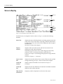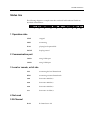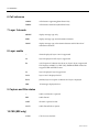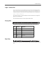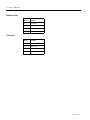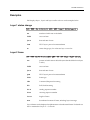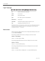
1
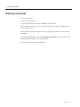
P R I M E S W I T C H ™ 1 0 0 / 5 0 0 P A P U S E R G U I D E ® ii Document Number Issued 10003137.00 Rev.1 March 1998 NETWORK EQUIPMENT TECHNOLOGIES, INC., (N.E.T.) PROVIDES THIS DOCUMENT AS IS, WITHOUT WARRANTY OF ANY KIND, EITHER EXPRESSED OR IMPLIED, INCLUDING, BUT NOT LIMITED TO, THE IMPLIED WARRANTIES OF MERCHANTABILITY AND FITNESS FOR A PARTICULAR PURPOSE. This document constitutes the sole Specifications referred to in N.E.T.’s Product Warranty for the products or services described herein. N.E.T.’s Product Warranty is subject to all the conditions, restrictions, and limitations contained herein and in the applicable contract. N.E.T. has made reasonable efforts to verify that the information in this document is accurate, but N.E.T. reserves the right to correct typographical errors or technical inaccuracies. N.E.T. assumes no responsibility for any use of the use of the information contained in this document or for any infringement of patents or other rights of third parties that may result. Networking products cannot be tested in all possible uses, configurations or implementations, and interoperability with other products cannot be guaranteed. The customer is solely responsible for verifying the suitability of N.E.T.’s products for use in its network. Local market variations may apply. This document is subject to change by N.E.T. without notice as additional information is incorporated by N.E.T. or as changes are made by N.E.T. to hardware or software. Copyright © 1998 Network Equipment Technologies, Inc. Copyright 1993 − 1998 Jtec Pty Limited. All rights reserved. No part of this publication may be stored in a retrieval system, transmitted or reproduced in any way, including, but not limited to, photocopy, photograph, magnetic, or other record, without the prior written permission of N.E.T.. Restricted Rights Legend (DFARS): Use, duplication, or disclosure by the Government of this document and any related computer software is subject to restrictions as set forth in subparagraph (c)(1)(ii) of the Rights in Technical Data and Computer Software clause at DFARS 252.227-7013. (FAR): Notwithstanding any other lease or license agreement that may pertain to, or accompany the delivery of, this document and any related computer software, the rights of the Government regarding its use, reproduction, and disclosure are as set forth in subparagraphs (c)(1) and (c)(2) of the Commercial Computer Software—Restricted Rights clause at FAR 52.227-19. Unpublished—rights reserved under the copyright laws of the United States. Network Equipment Technologies, Inc./N.E.T. Federal, Inc. 6500 Paseo Padre Parkway Fremont, CA. 94555 10003137.00 Rev.1 iii Trademarks The N.E.T. logo is a registered trademark, and PrimeSwitch, Network Equipment Technologies and N.E.T. are trademarks of Network Equipment Technologies, Inc. All other trademarks are the sole property of their respective companies. Note: In this manual, any reference to PrimeSwitch refers to the PrimeSwitch 100 Series product line, unless specified differently. iv 10003137.00 Rev.1 Contents v Contents Introduction About this user guide, 1-2 Audience, 1-2 Using this guide, 1-3 Overview, 1-4 Filtering, 1-4 Buffering, 1-4 Display, 1-5 Basic Rate access, 1-5 Installation Installing PAP, 2-2 Local, 2-2 Remote via ADLM, 2-2 Remote via modem, 2-3 Connecting PAP to an ISDN interface module, 2-4 BRMN, BRMT and early IPMN and IPMT, 2-4 Later IPMN and IPMT, 2-4 QBRM and DTM, 2-4 Connecting PAP to a PC, 2-5 Software installation, 2-7 Starting PAP, 2-8 The PAP screen Screen display, 3-2 Display colors, 3-4 Status line, 3-5 Layer 1 status line, 3-7 Primary Rate, 3-7 Basic Rate, 3-7 Examples, 3-9 Layer 1 status change, 3-9 Layer 2 frame, 3-9 Layer 3 message, 3-10 Item sources, 3-10 vi Contents Commands Entering commands, 4-2 Keys, 4-3 Commands, 4-4 10003137.00 Rev.1 Introduction 1-1 1 Introduction 1-2 About this user guide About this user guide This user guide describes the Protocol Analyzer Package (PAP). It covers the installation and operation of the PrimeSwitch 100 Series Integrated Services Digital Network (ISDN) PAP. PAP is available for both Primary Rate and Basic Rate in a number of protocol variations. The PrimeSwitch PAPTS14 is an ISDN Primary Rate monitor conforming to Austel Specification TS14. The PrimeSwitch PAPTS13 is an ISDN Basic Rate monitor conforming to Austel Specification TS13. The PrimeSwitch PAPETSI is an ISDN Primary Rate monitor conforming to the ETSI ISDN Specification. The PrimeSwitch PAPETSIB is an ISDN Basic Rate monitor conforming to the ETSI ISDN Specification. The PrimeSwitch PAPDASS2 is an ISDN Primary Rate monitor conforming to British Telecom Specification BTNR190. The PrimeSwitch PAPDPNSS is a PABX signaling monitor conforming to British Telecom Specification BTNR188. Audience This user guide is intended for people with a general knowledge of personal computers and a good understanding of ISDN, particularly layer 2 and layer 3 signaling protocols. 10003137.00 Rev.1 Introduction 1-3 Using this guide The guide contains the following sections: Overview describes how PAP processes network traffic. The PAP screen describes the main screen and illustrates how PAP displays messages. Commands describes how to control PAP with function keys and typed commands. Installation describes how to install PAP and connect PAP to a PC. Technical assistance information If there is a problem using the N.E.T. products, call the N.E.T. Technical Assistance Center (TAC) for assistance. The toll-free number for the United States is: 1-800-800-4638 The contact number for the UK and other European countries is: (44)1293 600703 Customers outside the United States, and Europe may use the following toll number: (703) 724 7999 TAC personnel are available by telephone 24 hours a day, 7 days a week. Warranty and contract customers receive first consideration in the scheduling of technical resources. Before contacting TAC for help, review and verify the provisions contained in your warranty or contract. Depending on those provisions, there may be a charge for service. When authorized, TAC Engineers can diagnose most network problems remotely, using dial-up connections. When a service technician is required, TAC will dispatch the nearest N.E.T. or third-party service engineer. 1-4 Overview Overview The PrimeSwitch ISDN Protocol Analyzer Package (PAP) monitors and displays layer 1, layer 2 and layer 3 protocol activity on a PrimeSwitch ISDN interface. PAP uses COM ports on the PC to transfer information to and from a PrimeSwitch ISDN module. PAP can monitor multiple ISDN interfaces on PrimeSwitch 100 Series modules which have more than one (for example, the DTM or QBRM), and can use either COM1, COM2 or BOTH at the same time on the PC. When PAP is operating, all traffic entering the analyzer system, either from the ISDN or from a captured file, is filtered, buffered and displayed. Filtering When you enable a filter, every message passing through the analyzer passes through the filter. Traffic that is selected by the filter enters the buffer. Traffic that is not selected is lost. Filters select or reject system, layer 1, layer 2 and layer 3 as follows: • System messages are information from other system modules. They can be on or off, but are generally not of concern to users. • Layer 1 status change messages can be on or off. • Layer 2 is filtered on frame type, for example, SABME and RR. They can be on, off, enabled for all except a defined list or enabled for a defined list only. • Layer 3 is filtered on message type, for example, SETUP and RELease. They can be on, off, enabled for all except a defined list or enabled for a defined list only. You create a filter with the MakeF command and display the current filter with the ShowF command (see Chapter 4 — Commands for more information). You can store several filters on disk but only one filter can be enabled at a time. Buffering After passing through the filter, messages are stored in the internal ‘first in first out’ (FIFO) buffer. Messages are also written to disk if you have enabled capturing. The full contents of each traffic item are stored irrespective of the current decoding and display settings. When the display is paused, traffic continues to be written to the buffer. Items in the buffer are numbered sequentially from zero until the buffer is full, then from zero again. This number appears alongside the message when it is displayed. Use the Save command to write the contents of the buffer to disk (see Chapter 4 — Commands for more information). The buffer is dynamically allocated from the PC’s memory. The default is to use Extended or Expanded memory, if it is available, and to use up all but 80 Kbytes of conventional memory if the Extended or Expanded memory is not available. 10003137.00 Rev.1 Introduction 1-5 This default can be overridden from the command line as follows: PAPXXXX REAL forces the PAP software to use conventional memory and will not operate if insufficient conventional memory is available. PAPXXXX VIRTUAL forces the PAP software to use Extended or Expanded memory and will not operate if memory is not available. These overrides should not be used unless problems are experienced with the default. The size of the buffer therefore depends on the amount of memory (RAM) available in the computer, and the amount used by other programs. The buffer size is displayed on the startup screen. Multiply this by four to determine the number of traffic items that can be stored. Display Traffic is displayed on the screen according to the current settings of layer 2 and layer 3 decoding and display (L2, L3, Long, Med, and Short commands). You can pause the display to examine messages and scroll the display backwards and forwards. See Chapter 4 — Commands for more information. Basic Rate interface To understand the information displayed by the Basic Rate PAP you must understand Service Access Point Identifiers (SAPIs), Terminal Endpoint Identifiers (TEIs) and Connection Endpoint Suffices (CESs). A data link connection is identified by a SAPI and a TEI. The SAPI defines which part of the bit within a terminal is talking and can have three different values: 0 LAPD link for ISDN calls 16 LAPB link for X.25 calls 63 management bit which manages TEIs The TEI is a unique address (for a particular ISDN connection) assigned to a terminal. The analyzer displays two types of TEI: Fixed set physically on a terminal, usually by DIP switches or non-volatile storage. You must ensure that each fixed TEI terminal has a unique address; if two terminals have the same address, neither will work. Automatic worked out dynamically by negotiation between network and terminal. The TEI and SAPI combine to make a physical address that is encoded into layer 2 frames. Layer 3 refers to this combination by a CES. This is a number between 0 and 255 which at any time uniquely identifies a particular SAPI/TEI combination. 1-6 Overview Figure 1 shows the relationship between CES, SAPI and TEI. Figure 1: CES, SAPI and TEI 10003137.00 Rev.1 Installation 2-1 2 Installation 2-2 Installing PAP Installing PAP PAP can be used to monitor traffic on either a local or a remote PrimeSwitch. Local To monitor local traffic connect the PC to the PrimeSwitch PAP connector, as in the following diagram: PC PAP PrimeSwitch Figure 2: Local connection Remote via ADLM To monitor remote traffic, a V.24 ADLM must be installed in both the local and remote PrimeSwitches. Connect the PAP connector to an ADLM V.24 port on the remote PrimeSwitch, and connect the PC to an ADLM V.24 port on a local PrimeSwitch, as in Figure 3: PC ADLM Local PrimeSwitch ISDN PAP ADLM Remote PrimeSwitch Figure 3: Remote connection 10003137.00 Rev.1 Installation 2-3 Remote via modem You can also use a modem to monitor traffic on remote PrimeSwitches, as shown in Figure 4. PC PACER 2200 Modem PAP PACER 2200 PrimeSwitch Figure 4: Local connection via modem Modem Analog Network 2-4 Connecting PAP to an ISDN interface module Connecting PAP to an ISDN interface module BRMN, BRMT and early IPMN and IPMT You must place the PrimeSwitch PAP Module panel in the slot immediately to the right of the ISDN interface module that you want to monitor, with the connector located at the top. If necessary, rearrange the modules in the PrimeSwitch to clear the slot on the right hand side of the ISDN interface module. Note that you must update the configuration of the PrimeSwitch to reflect the new arrangement of modules. Connect the 10-way IDC connector on the PrimeSwitch PAP Module panel to the 10-way header located just above the RJ-45 socket on the ISDN interface module. The red conductor of the ribbon cable must be on the top. Place the panel into the vacant slot and tighten the screws located on the top and bottom of the panel. Later IPMN and IPMT These modules have a 9-way socket on the front panel to connect to PAP. QBRM and DTM The QBRM and DTM have a 9-way socket on the front panel to connect to PAP. This PAP connection services all 4 interfaces. 10003137.00 Rev.1 Installation 2-5 Connecting PAP to a PC Connect the PrimeSwitch PAP protection device to a parallel port of the PC. To monitor local traffic: 1 Connect COM1 or COM2 on the PC to the 25-way D type connector on the PrimeSwitch PAP panel using a straight through cable constructed according to Figure 5. 3 2 2 3 3 7 7 5 DB 25 Female (to PC) DB 25 Male (to PAP V.24 por t) DB 9 Male (to b uilt-in P AP por t) OR 2 Figure 5: Local cable construction To monitor remote traffic: 1 Connect the PC to an ADLM V.24 port on the local PrimeSwitch using a cable constructed according to Figure 6. 2 3 3 2 7 7 5 DB 25 Male (to ADLM V.24 por t) DB 25 Female (to PAP por t) DB 9 Male (to b uilt-in P AP por t) Figure 6: Remote cable construction 2 OR 3 2-6 Connecting PAP to a PC 2 Configure the ADLM V.24 as follows: Remote Auto answer ON Remote and local AT call control ON Bit rate 19 200 Parity No Stop bits 1 Number of bits 8 10003137.00 Rev.1 Installation 2-7 Software installation The PAP software is installed as part of the PrimeSwitch Manager—NCS (Net Center Software) installation process. To install individual versions: 1 Create a directory for the PAP software. Type: MD \PAP <Enter> 2 Change to this directory. Type: CD \PAP <Enter> 3 Insert the PAP disk (PM-NCS Disk 3) into the floppy drive and change to the PAP subdirectory. Type: CD A:\PAP <Enter> 4 Expand the required file. Type: expand A:PAPTS14.EXE <Enter> expand A:PAPTS13.EXE <Enter> expand A:PAPETSI.EXE <Enter> expand A:PAPETSIB.EXE <Enter> expand A:PAPDASS2.EXE <Enter> expand A:PAPDPNSS.EXE <Enter> 2-8 Starting PAP Starting PAP To start the program: 1 Either: • from Program Manager, double-click on the icon; or • from MS-DOS, change to the PAP directory and type one of the following: PAPTS14 <Enter> PAPTS13 <Enter> PAPETSI <Enter> PAPETSIB <Enter> PAPDASS2 <Enter> PAPDPNSS <Enter> To change the COM port or baud rate settings, use the Port and/or Rate commands (see Chapter 4 — Commands). Changes are saved when the program exits and will be used each time the program starts. 10003137.00 Rev.1 The PAP screen 3-1 3 The PAP screen 3-2 Screen display Screen display Status line Display window Layer 1 status line Command window Command line Figure 7: Screen display for Primary Rate Access The PAP screen, an example of which is shown in Figure 7, contains the following elements: Status line displays the status of the PrimeSwitch, including operation state, link status, level of layer 2 and layer 3 decoding, and other information. For Basic Rate access, the current CES is displayed at the far right of the status line. See Status line later in this chapter. Display window displays traffic sent and received, and lists the contents of the message pool and other information. When the program starts it shows a block diagram with credits, software version, connection information and buffer size. Use the cursor keys to scroll through a display that is longer than the window. See Keys in Chapter 4 — Commands. Layer 1 status line displays the network and user layer 1 states. These are only updated during monitoring. See Layer 1 status line later in this chapter. Command window displays entered commands. See Commands in Chapter 4 — Commands. Command line displays function key definitions of commands. Available commands depend on the current operation. Help window (not shown) temporary window displayed over the rest of the screen. 10003137.00 Rev.1 The PAP screen 3-3 The Basic Rate screen differs from the Primary Rate screen in the following ways: • the Call Reference Indicator has two digits, not four; • the current CES indicator is at the far right of the status line; • there is a different set of layer 1 state indicators; • the startup display shows different connection ports. 3-4 Display colors Display colors On a color monitor, traffic is displayed in the following colors: Green Network side, layers 2 and 3. Purple User side, layers 2 and 3. Yellow Layer 1. 10003137.00 Rev.1 The PAP screen 3-5 Status line The following diagram is a sample status line with each field numbered. Fields are described in detail below. 1 2 3 4 5 1 Operation state STOP stopped MON monitoring PLAY playing back captured file PAUSE display paused 2 Communication port COM1 using COM1 port COM2 using COM2 port 3 Local or remote, or bit rate LOC monitoring the local PrimeSwitch REM monitoring a remote PrimeSwitch 2400 data rate is 2400 bit/s 4800 data rate is 4800 bit/s 9600 data rate is 9600 bit/s 19.2 data rate is 19.2 kbit/s B=XX B-channel set to XX 4 Not used 5 B-Channel 6 7 8 9 10 3-6 Status line 6 Call reference OXXXX call reference originating (Basic Rate OXX) DXXXX call reference destination (Basic Rate DXX) 7 Layer 3 decode SHORT display message type only MED display message type and information elements LONG display message type, information elements and full decode of information elements -- alarms displayed; layers 2 and 3 suppressed L2 layer 2 displayed in full; layer 3 suppressed E2 only Exception Conditions are shown on layer 2; layer 3 suppressed. This displays SABME, UA, DISC, REJ, FRMR and RNR frames but suppresses RR and INFO frames L3 layer 3 displayed; layer 2 suppressed L2 L3 layers 2 and 3 displayed in full E2 L3 (default) layer 2 exception conditions and layer 3 displayed HEX all messages displayed in hex 8 Layer enable 9 Capture and filter status -- traffic not filtered or captured FILT traffic filtered CAPT all traffic captured to disk CA-FI traffic filtered before capture 10 CES (BRI only) C XXX CES of active data link 10003137.00 Rev.1 The PAP screen 3-7 Layer 1 status line Layer 1 status indicators are decoded from the value at the end of the displayed line, which is the sum of the individual hexadecimal values shown in the tables below. For example, simultaneous Primary Rate SYNC (08) and SES (02) errors are displayed as: Layer 1 Status Change 0A The left half of the layer 1 status line displays network side indicators, the right half displays user side indicators. There are different indicators for Primary Rate and Basic Rate. Primary Rate The indicators are the same for both network and user sides, as shown below. Value Indicator Description 00 -- normal operation 01 ES Errored Second 02 SES Severely Errored Second 04 DM Degraded Minute 08 SYNC frame synchronisation lost 10 REM remote alarm 20 AIS Alarm Indication Signal (binary ones) Basic Rate The indicators are different for user and network sides, as shown in the tables over the page. 3-8 Layer 1 status line Network side Value Indicator 00 deactivated 01 pending deactivation 02 pending activation 03 activated Value Indicator 00 deactivated 01 synchronized 02 activation request 03 activated User side 10003137.00 Rev.1 The PAP screen 3-9 Examples PAP displays layer 1, layer 2 and layer 3 traffic as shown in the examples below. Layer 1 status change 001 number of traffic item in the buffer USER source of item Jan 03 date and time of item G821 ITU-T layer 1 protocol recommendation 00 status change type, for values see Layer 1 status line 030 position of traffic item in the buffer (note that this differs from layers 1 and 3) USER source of item Jan 03 date and time of item Q921 ITU-T layer 2 protocol recommendation INFO frame type CR0 Command/Response bit setting PF0 Poll/Final bit setting Ns=11 sending sequence number Nr=59 receiving sequence number Len=13 length of frame 00 01 hexadecimal contents of frame, including layer 3 message Layer 2 frame Layer 2 frames can be displayed in alphanumeric or hexadecimal format. For details see the L2 command in Chapter 4 — Commands. 3-10 Examples Layer 3 message 031 number of traffic item in the buffer USER source of item Jan 03 date and time of item Q931 ITU-T layer 3 protocol recommendation INFOrmation message type C/Ref 0001e call reference number, unique for duration of call Org originating or destination side of call The first line of a layer 3 message always has the same format, although the amount of information displayed depends on the level of decoding (see Long, Med and Short commands in Chapter 4 — Commands). Item sources When monitoring one ISDN interface from one COM port (the default), the item source is either USER or NETWORK. If monitoring one ISDN interface from two COM ports, the source is either: USER(n) or NETWORK(n) where n = 1 or 2 (for COM1 or COM2). If monitoring multiple ISDN interfaces from one COM port, the source is either: USER Pm or NET Pm where m = 1 to 4 (for the ISDN interface). If monitoring multiple ISDN interfaces from two COM ports, the source is either: U(n) Pm or N(n) Pm where n = 1 or 2 (for COM1 or COM2) and m = 1 to 4 (for the ISDN interface). 10003137.00 Rev.1 Commands 4-1 4 Commands 4-2 Entering commands Entering commands To enter a command: • press a Function key, or • type the command name and press Enter or the space bar. Some commands prompt for a yes/no response. Type y or Y and press Enter for yes, n or any other key for no. Some commands prompt with a list of choices. Type the first letter of a word to select that option. Some commands display a list. Use the Page Up, Page Down and arrow keys to scroll through the list, then type a choice from the list. To cancel the command prompt, press Esc. 10003137.00 Rev.1 Commands 4-3 Keys Key functions are shown below. Key Context Function Function keys all executes command Up arrow ↑ monitoring pauses display paused display or list scrolls up one line paused display or list scrolls down one line end of paused display continues display monitoring pauses display paused display or list scrolls up one screen paused display or list scrolls down one screen end of paused display continues display Home paused display goes to start of display End paused display goes to end of display Enter command prompt executes command Spacebar command prompt executes command Esc command prompt cancels command Help window closes window Down arrow ↓ PgUp PgDn 4-4 Commands Commands This section describes the available commands. You should note that not all commands are available in every analyser state. You can display a complete list of the commands available in the current state using the MORE key. Capt Toggles capture to disk. If capture is OFF, you must supply a filename for the capture file. This should be a legal DOS filename, for example, CAPTURED.OUT. All transmitted and received messages are stored in this file. Files can be played back using the Play command. All messages that pass through the Filter (see Filt) are stored regardless of the settings of L2, L3 and LONG, MEDium and SHORT. To end capture, either press Capt again or press Stop. If the disk fills up capture terminates. When capture is ON, CAPT is displayed in field 9. Cause Displays a list of causes and their values. Cont Continues display after the display has been paused to examine data. The display can also be continued using the down arrow (↓) or Page Down keys to move past the end of the display. Dial Dials a remote number before monitoring starts. Requires an AT modem, or a QDLM or ADLM. Filt Enables or disables a filter. If a filter is not enabled, you must supply the name of a filter that you want to use to select messages for display. If a filter is enabled, it is removed and all messages are displayed. The status line indicates FILT when filtering is enabled in the Filter/Capture field. If both filtering and capturing are on, CA-FI is displayed. You must define a filter before you can use the Filt command (see MakeF). Hang Disconnects a remote monitoring call. 10003137.00 Rev.1 Commands 4-5 Help Displays information relevant to the currently selected command or operation. To get more help, press C to display a list of commands or T to display a list of topics. Move the pointer with the cursor keys and press Enter to select. Press Esc or Q to return to normal operation. Info Displays a list of Information Elements and their values. L2 Changes the display of layer 2 protocol activity. The display level (as indicated on the top line) has four settings: --- no display of layer 2 E2 only exception conditions are shown; RR and INFRO frames are suppressed L2 full display of layer 2 HEX display in hexadecimal All layer 2 activity is buffered/captured at all times regardless of this setting. L3 Changes the display of layer 3 protocol activity. The display level (as indicated on the top line) has two settings: -- no display of layer 3 L3 display of layer 3 All layer 3 activity is buffered/captured at all times regardless of this setting. Long Selects long display of layer 3. The display includes Message Type, each Information Element and the full interpretation of each octet within the Information Elements. LONG appears on the status line. 4-6 Commands MakeF Creates a filter. You must supply a name and then answer a series of yes/no questions to define the filter. You can choose whether to select All, Only the listed ones or all Except the listed ones. If you select Only or Except, you can enter a list of Frame Types or Message Types. When the list contains all of your selections, press Enter on a blank line to finish. You can enable the filter immediately. The filter is stored in a disk file named NAME.FLT where NAME is the name you give to the filter. Med Selects medium display of layer 3. The display includes Message Type, Information Elements and the contents of Information Elements in hexadecimal, but not the interpretation of the element contents. MED is displayed on the status line. Mnem Displays a list of message mnemonics and their values. Mon Monitors traffic in both directions. MON appears on the status line. Some PrimeSwitch modules have multiple ports. You can choose to have one or more of these ports monitored. For single port modules (for example, the IPM or BRM), leave this set to its default value, which is port 1. For multiple port modules (for example, the DTM or QBRM), enter 1, 2, 3 or 4, or multiples such as: 13 to monitor ports 1 and 3 1234 to monitor all 4 ports, and so on. MSDOS Loads a copy of the MS-DOS command processor. The MS-DOS prompt is displayed and you can run most DOS commands. There is only a limited amount of memory available, so you may find that larger programs do not run. To return to the analyser, type Exit and press Enter. 10003137.00 Rev.1 Commands 4-7 Pause Suspends the display of information during monitoring. Pressing the up arrow (↑) or Page Up key also pauses the display. While the display is paused, information received by PAP is buffered and captured to disk. Press Cont to continue display. Play Plays back a file that has been created using the Capt or Save commands. When you supply the filename of a legal capture file, the sequence in the file is played back and the status line indicates PLAY in field 1. The first page is displayed and you can view subsequent lines by using the Page Up, Page Down and arrow keys. The L2, L3, Long, Med and Short commands control the display level. Playback is ended at the end of the file, or when you press STOP. Port Selects which COM port to use. Choose 1 or 2. If you have a PC with two COM ports, you can monitor two different PrimeSwitch modules at the same time; in this case, select BOTH as the value. This value is saved for use the next time the software is opened. Print Prints a file of transactions that has been captured on disk. You can print the file to a disk file by selecting Disk, rather than Printer, as the print destination. Messages are decoded and displayed according to the current settings of the L2, L3, Long, Med and Short commands. The print file is standard ASCII text. Quit Exits from PAP and returns to the MS-DOS prompt. Save Saves the current contents of the PAP internal buffers to a disk file. The file is in the same format as a Capture file and can be read using the Play command. Short Selects short display of layer 3. Disassembly of messages is restricted to type only. SHORT is displayed on the status line. 4-8 Commands ShowF If filtering is enabled, the current filter settings are shown. Speed Selects which data rate to use. The value can be 2400, 4800, 9600 or 19200. This value is saved for use the next time the software is opened. State Displays a list of states and their values. Stop Terminates the current activity as shown in the table below. Operation state Effect Monitor mode Returns to stopped state Playing back File closed, returns to stopped state Tele Displays a list of teleservice types and their values. 10003137.00 Rev.1