1
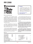
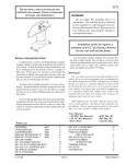
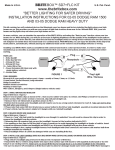
2101 WARNING: Do not inflate this assembly when it is unrestricted. The assembly must be restricted by the suspension or other adequate structure. Do not inflate beyond 100 P.S.I. Improper use or over inflation may cause property damage or severe personal injury. INSTALLATION INSTRUCTIONS Congratulations - your new Air Helper Springs are quality products capable of improving the handling and comfort of your vehicle. As with all products, proper installation is the key to obtaining all of the benefits your kit is capable of delivering. Please take a few minutes to read through the instructions to identify the components and learn where and how they are used. It is a good idea to start by comparing the parts in your kit with the parts list below. Your kit includes separate inflation valves and air lines for each air helper spring. This will allow you to level your vehicle from side to side as well as from front to back. If you would rather have a single valve inflation system, your dealer can supply the required "T" fitting. IMPORTANT! The heart of the air helper spring kit is, of course, the air helper springs. Remember that the air helper springs must flex and expand during operation, so be sure that there is enough clearance to do so without rubbing against any other part of the vehicle. For your safety and to prevent possible damage to your vehicle, do not exceed the maximum load recommended by the vehicle manufacturer (GVWR). Although your Air Helper Springs are rated at a maximum inflation pressure of 100 P.S.I., this pressure may allow you to carry too great a load on some vehicles. Check your vehicle owner’s manual for maximum loads listed for your vehicle. Be sure to take all applicable safety precautions during the installation of the kit. The instructions listed in this brochure and the illustrations all show the left, or driver’s side of the vehicle. To install the right side assembly simply follow the same procedures. When inflating your Air Helper Springs, add air pressure in small quantities, checking pressure frequently during inflation. The air spring requires much less air volume than a tire and, therefore, inflates much quicker. PARTS LIST 267C AIR SPRING UPPER BRACKET (RIGHT) UPPER BRACKET (LEFT) LOWER BRACKET AXLE STRAP HEAT SHIELD 3/8" -16 x 1" HEX BOLT 3/8" -16" x 3" CARRIAGE BOLT 3/8" -16 FLANGED LOCK NUT 3/8" -16 x 3/4" HEX BOLT 1/4" -20 x 1" HEX BOLT 1/4" FLAT WASHER 21-8156 6781 5157 5158 5159 1163 1004 2 1 1 2 2 1 4 4 12 2 2 4 12-03 3/8" LARGE FLAT WASHER 1/4" LOCK WASHER 1/4" HEX NUT PUSH-TO-CONNECT MALE AIR FITTING PUSH-TO-CONNECT INFLATION VALVE 5/16" FLAT WASHER AIR LINE TUBING NYLON TIE THERMAL SLEEVE 4 2 2 3046 2 3032 2 4 1 6 2 NCD-5988-2 2101 KIT ASSEMBLY FIGURE "A" UPPER BRACKET NOTE: Both illustrations are of the left, or drivers side, of the vehicle. Reverse any orientations when assembling and installing the right, or passenger, side of the vehicle. 3/8” -16 FLANGED HEX NUT KIT TO FRAME ASSEMBLY 1/4” FLAT WASHER 1/4” -20 x 1” HEX BOLT E 1/4” LOCK WASHER F R A M 1/4” FLAT WASHER 3/8” -16 FLANGED HEX NUT 1/4” -20 HEX NUT 3/8” -16” FLANGED HEX NUT 3/8” LARGE WASHER (SEE NOTE 1) AIR SPRING 3/8” LARGE WASHER (SEE NOTE 1) AIR FITTING AIR LINE USE THIS HOLE FOR 2WD VEHICLES USE THIS HOLE FOR 4WD VEHICLES 3/8” -16 x 3” CARRIAGE BOLT 3/8” -16 x 1” HEX BOLT LOWER BRACKET 3/8” -16 x 3/4” HEX BOLT 3/8” -16 x 1” HEX BOLT LEAF STACK 3/8” -16 x 3” CARRIAGE BOLT AXLE NOTE 1: L E E H W F R O N T AXLE STRAP Use 3/8 large flat washer between upper bracket and frame rail only if rivet head is present on bottom of frame. Rivet head will prevent flush mounting of the upper bracket to the frame rail. 3/8” -16 FLANGED LOCK NUT STEP 1 - PREPARE THE VEHICLE Remove the positive battery cable. With the vehicle on a solid, level surface chock the front wheels. Raise the vehicle by the axle and remove the rear wheels. After the removal of the wheels lower the vehicle so the axle rests on jack stands rated for your vehicles weight. This installation assumes that there is no load in the truck. TWO-WHEEL DRIVE VEHICLES NOTE: This kit is designed to fit both two-wheel and four-wheel drive vehicles. The jounce bumper and brackets must be removed for installation of this kit. The jounce bumper and bracket on the two-wheel drive can be unbolted and removed see Figure "B". The jounce bumper and bracket on the four-wheel drive may be bolted or riveted in place, depending on model year. Simply unbolt the jounce bumper bracket and remove from the frame see Figure "C". On older models, remove the jounce bumper by drilling out two rivets that fasten the bracket to the frame. Complete the removal by cutting off the heads with a cold chisel. The completion of the kit installation is the same for the two-wheel and four-wheel drive. FIGURE "B" STEP 2 - PRE-ASSEMBLE THE KIT This kit is supplied with a right and left upper bracket. Begin by installing the left (driver's side) upper bracket. This bracket will have the "over-bent tab" see Figure "D". The lower bracket is the same for both sides. Align the studs on the top of one of the air springs with the mounting holes in the upper bracket while ensuring that the air hole is visible through the slot in the upper bracket. Insert the studs into the holes and secure the air spring to the upper bracket with 3/8" -16 flanged lock nuts see Figure "A". Next, install the male push-to-connect air fitting in the air inflation hole. Tighten the air fitting securely to engage the orange thread sealant. To attach the lower bracket to the air spring, first position the bracket on the axle housing over the jounce pad see Figures "A" & "E". Position the bracket so that the narrow end is toward the center of the vehicle. The air spring must be secured to the lower bracket through the forward hole. Once the correct mounting hole for the lower bracket has been identified, remove the bracket from the axle and fasten to the air spring using a 3/8" -16 x 3/4" hex bolt (finger tight). Note that this bolt will be tightened in Step 3. SOME FOUR-WHEEL DRIVE VEHICLES MAY HAVE BOLTS, OTHERS WILL HAVE RIVETS FIGURE "C" STEP 3 - INSTALL THE ASSEMBLY TO THE VEHICLE FRONT OVER-BENT TAB VIEW OF DRIVER’S SIDE ASSEMBLY FROM INSIDE OF VEHICLE FIGURE "D" FRAME RAIL UPPER BRACKET LEAF STACK AIR SPRING LOWER BRACKET AXLE BRAKE LINE DRIVER'S SIDE SHOCK BRACKET BRACKET STRAP FRONT FIGURE "E" Set the assembly in place on the axle housing over the jounce pad. The lower bracket should butt against the U-bolts on the leaf spring see Figure "E". Position the assembly so that the upper bracket is aligned vertically against the outside surface of the frame rail. On some vehicles there may be a rivet head on the bottom of the bottom surface of the frame rail that will prevent the upper bracket from being mounted flush against the frame. To assure that the upper bracket clears the rivet head, install four large flat washers between the upper bracket and the bottom surface of the frame rail see Figure "A". Installation of the flat washers is only necessary if your vehicle has a rivet head on the bottom of the frame rail. Insert a 1/4" -20 x 1" bolt through the vertical tab of the upper bracket and an existing hole in the frame rail. Secure with washers and a nut see Figure "A". On some models, a hole must be drilled in the frame rail for the bolt to pass through. Using the upper bracket as a template, drill a 5/16" hole though the frame rail. Make sure that all electrical, brake, and fuel lines are cleared from the path of the drill. The tabs on the bracket will be secured to the lower frame flange using 3/8" flanged lock nuts and 3/8"-16 x 1" hex bolts see Figure "A". Note: on the driver's side of the vehicle the 1/4" bolt will also hold a clip (on some models) used to hold brake and fuel lines. Secure the clip to the 1/4" bolt to secure the lines. Align the lower bracket against the U-bolts over the leaf spring stack see Figure "E". After the bracket has been squared with the U-bolts, tighten the 3/8" hex bolt to secure the lower bracket to the air spring. Next, insert two 3/8" -16 x 3" carriage bolts into the square holes on the lower bracket. Install one axle strap on the bottom of the axle housing see Figure "A". Slide the axle strap on to the carriage bolts and secure with 3/8" -16 flanged lock nuts. This installation will hold the lower bracket in place. Note: When installing the left-side assembly, it will be necessary to tie the parking brake line to the sway bar to prevent it from contacting the air spring in normal operation. There must be at leat 1/2" of clearance between the inflated air spring and any other part of the vehicle. STEP 4 - INSTALL THE PASSENGER'S SIDE ASSEMBLY HEAT SHIELD Follow steps 1 - 4 for assembly and installation of the passenger's side assembly. On the passenger's side it will be necessary to install a heat shield between the upper bracket and the air spring to protect the air spring from the exhaust pipe heat see Figure "F". Position the heat shield so that it will reflect radiant heat from the point on the exhaust pipe closest to the air spring. The heat shield should be positioned so that it does not contact the axle housing as the suspension compresses. FIGURE "F" AIR SPRINGS STEP 5 - INSTALL THE AIR LINE AND THE INFLATION VALVE AIR HOSE INFLATION VALVES BUMPER FIGURE "G" AIR LINE Uncoil the air line tubing and cut it into two equal lengths. DO NOT FOLD OR KINK THE TUBING. Try to make the cut as square as possible. Insert one end of the tubing into the air fitting installed in the top of the air helper spring. Push the tubing into the fitting as far as possible. Select a location on the vehicle for the air inflation valves. The location can be on the bumper or the body of the vehicle, as long as it is in a protected location so the valve will not be damaged, but maintain accessibility for the air chuck see Figure "G". Drill a 5/16" hole and install the air inflation valve using two 5/16" flat washers per valve as supports see Figure "H". Run the tubing from the air helper spring to the inflation valve, routing it to avoid direct heat from the exhaust pipe and away from sharp edges. Thermal sleeves have been provided for these conditions. If a thermal sleeve is required simply slide the sleeve over the air line tubing to the location requiring protection. The air line tubing should not be bent or curved sharply as it may buckle. Secure the tubing in place with the nylon ties provided. Push the end of the air line tubing into the inflation valve as illustrated see Figure "H". FLAT WASHER STEP 6 - CHECK THE AIR SYSTEM Once the inflation valves are installed inflate the air helper springs to 70 P.S.I. and check the fittings for air leaks with an applied solution of soap and water. If a leak is detected at a tubing connection, check to make sure that the tube is cut BODY OF VEHICLE as square as possible and that it is pushed completely into the fitting. The tubing can easily be removed from the fitting by first releasing the pressure from the air HEX NUT spring, then by pushing the collar towards the body of the fitting and then pulling VALVE CAP out the tube. If a leak is detected where the air fitting screws into the spring, release FIGURE "H" the air pressure, then remove the tubing as described above, then screw the brass fitting into the air spring one additional turn or until the leak stops. Reinstall the tubing and reinflate the air springs and check for leaks as noted above. This now completes the installation. Install the wheels and torque the lug nuts to the manufactures specifications. Raise the vehicle by the rear axle and remove the jack stands and lower the vehicle back onto the ground. Re-attach the positive battery cable and remove the wheel chocks from the wheels. Before proceeding, check once again to be sure you have proper clearance around the air springs. With a load on your vehicle and the air helper springs inflated, you must have at least 1/2" clearance around the air springs. As a general rule, the air helper springs will support approximately 50 lbs. of load for each P.S.I. of inflation pressure (per pair). For example, 50 P.S.I. of inflation pressure will support a load of 2500 lbs. per pair of air helper springs. FOR BEST RIDE use only enough air pressure in the air helper springs to level the vehicle when viewed from the side (front to rear). This amount will vary depending on the load, location of load, condition of existing suspension and personal preference. PUSH-TO-CONNECT INFLATION VALVE NOTE: Too much air pressure in the air helper springs will result in a firmer ride, while too little air pressure will allow the air helper spring to bottom out over rough conditions. Too little air pressure will also not provide the possible improvement in handling. TO PREVENT POSSIBLE DAMAGE MAINTAIN A MINIMUM OF 5 P.S.I. IN THE AIR HELPER SPRINGS AT ALL TIMES. NOTE: Once the air helper springs are installed, it is recommended that the vehicle not be lifted by the frame, as over-extension may occur, resulting in damage to the air helper springs. However, should it become necessary to raise the vehicle by the frame, deflate both air helper springs completely.