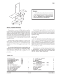
1
350 S. St. Charles St. Jasper, In. 47546
Ph. 812.482.2932 Fax 812.634.6632
www.ridetech.com
Part # 11330199
63-72 C-10 Level 1 Air Suspension System
Front Components:
1
11331099
Front CoolRide Kit for Stock Lower Arms
1
11330500
Black Series Front Shock Kit w/ Mounts
Rear Components:
1
11334099
Rear CoolRide Kit
1
11330700
Black Series Rear Shocks
Compressor System:
1
30154000
3 gallon RidePro Compressor Kit (Analog Gauges)
350 S. St. Charles St. Jasper, In. 47546
Ph. 812.482.2932 Fax 812.634.6632
www.ridetech.com
Part # 11331099
63-87 Chevy C10 Front CoolRide Kit
For Use w/ Stock Lower Arms
Components:
2
90006873
Front air springs – 224C
2
90000060
Upper air spring plate
2
90000057
Lower air spring cup bracket
2
90001083
Medium bump stops – 1.5” tall
1
90000293
Driver side steering stop
1
90000294
Passenger side steering stop
Hardware Kit:
16
99372002
3/8” USS Nylok nut
Air spring mounts
2
99371001
3/8” x 3/4” USS bolt
Air spring to lower cup bracket
2
99373005
3/8” lock washer
Air spring to lower cup bracket
4
99371003
3/8” x 1” USS bolt
Steering stop to lower arm
8
99371004
3/8” x 1 ¼” USS bolt
Upper mount to frame
30
99373003
3/8” SAE flat washer
Installation Instructions
1. Raise and support truck at a safe, comfortable working height. Let the front suspension hang
freely.
2. Remove coil spring, shock absorber and bump stop. Refer to factory service manual for proper
disassembly procedure.
3. Hold the upper plate to the cross
member as shown in the picture to the
left and clamp to frame. Using the
plate as a template drill 4 holes in the
cross member.
4. Apply thread sealant to the air fitting
and thread into the air spring.
Remove the upper plate from the frame
and place onto the studs on the top of
the air spring. The holes are lettered;
slide the plate to position B moving the
air spring to the rear of the vehicle.
Secure with flat washers and nyloc
nuts. Route airline.
5. Bolt the lower bracket to the air
spring using a 3/8” x 3/4" bolt, lock
washer and flat washer.
6. Attach the air spring assembly to
the frame using 3/8” x 1 ¼” bolts, Nylok
nuts and flat washers supplied. The
lower mount will simply sit in the coil
spring pocket. It does not need to be
attached.
7. Replace the factory shock, with the
new ones supplied.
8. Bolt the steering stop to the lower
arm. Check air spring clearance with
the caliper at full lock. The air spring
should be about 5” tall at ride height.
DO NOT ALLOW THE AIR SPRING TO RUB. THIS WILL DAMAGE THE AIR
SPRING AND IS NOT A WARRANTABLE SITUATION.
350 S. St. Charles St. Jasper, In. 47546
Ph. 812.482.2932 Fax 812.634.6632
www.ridetech.com
Part # 11330500
63-72 C-10 Black Series Front Shock Kit
For Use w/ Stock Lower Arms
Components:
2
20000009
Shock absorbers – Eye/Eye
2
90001617
Upper shock studs
350 S. St. Charles St. Jasper, In. 47546
Ph. 812.482.2932 Fax 812.634.6632
www.ridetech.com
Part # 11330700
63-72 C-10 Rear Black Series Shock Kit
For Use w/ Stock Suspension
Components:
2
20000012
Black Series shock – eye/eye
350 S. St. Charles St. Jasper, In. 47546
Ph. 812.482.2932 Fax 812.634.6632
www.ridetech.com
Part # 11334099
63-72 Chevy C-10 Rear CoolRide Kit
For Use w/ Factory Trailing Arms
Components:
2
90006781
Front air spring – 267c
2
90000056
Upper air spring cup bracket
2
90000070
Lower air spring plate
2
90001082
Short bump stop
Hardware Kit:
4
99372002
3/8” USS Nylok nut
Air spring to upper mount
4
99373003
3/8” SAE washer
Air spring to upper mount
2
99435003
7/16” x 2” stud
Upper mount to frame
2
99432001
7/16” Nylok nut
Upper mount to frame
2
99433002
7/16” SAE washer
Upper mount to frame
2
99371009
3/8” x 4” bolt
Air spring to trailing arm
2
99373001
3/8” fender washer
Air spring to trailing arm
2
99373005
3/8” lock washer
Air spring to trailing arm
Installation Instructions
1. Raise the vehicle to a safe and comfortable working height with the suspension hanging
freely.
2. Remove the coil spring and shock absorbers.
3. Apply thread sealant to a 90 degree
air fitting and screw it into the top of the
air spring.
Note: When using larger fittings you
may need to trim the bracket and/or
frame rail.
4. Place the upper mount over the
studs on the air spring. Secure with
two 3/8” Nylok nuts and flat washers.
5. Screw the 7/16 x 2” stud into the nut
in the bottom of the bracket.
7. Bolt the assembly to the upper coil
spring pocket with the stud sticking
through the frame. Use a 7/16” nut
and flat washer to fasten the assembly.
8. Bolt the bottom of the air spring to
the trailing arm using a 3/8” x 4” bolt,
fender washer and lock washer. The
lower air spring plate must be installed
between the air spring and the trailing
arm.
9. Double check air spring clearance
though full suspension travel.
10. Ride height on this air spring is
approximately 5”.
DO NOT ALLOW THE AIR SPRING TO RUB. THIS WILL DAMAGE THE AIR
SPRING AND IS NOT A WARRANTABLE SITUATION.
350 S. St. Charles St. Jasper, In. 47546
Ph. 812.482.2932 Fax 812.634.6632
www.ridetech.com
Part # 30154000
4000 Series RidePro 4 Way Compressor System
3 Gallon Tank – Analog Gauges
Components:
1
31920002
Thomas 327 Compressor
1
31194000
RidePro 4 Way analog control panel with rocker switches (Black Face)
1
31913100
3 gallon aluminum tank
1
31934001
RidePro 4 Way valve block
1
31980005
Pressure switch – 135 On / 150 Off
Wiring:
1
90001924
Fuse holder
1
90001922
20 Amp fuse
2
31900036
Wiring harness - Control panel to valve
Airline & Fittings:
2
31940002
1/4” DOT airline - 30 ft. roll - valve block to gauges
2
31940000
1/8” DOT airline - 25 ft. roll - valve block to gauges
1
31952150
1/8”npt x 1/4” tube female straight - compressor
1
31957003
2” Brass Nipple - compressor
6
31954201
1/4” npt x 1/4” tube Elbow airline fitting
7
31954000
1/4” npt x 1/4” tube Straight airline fitting
4
31952000
1/8” npt x 1/8” tube Straight fitting - manifold to gauge fitting
1
31957004
1/4” npt plug - plug unused supply port
350 S. St. Charles St. Jasper, In. 47546
Ph. 812.482.2932 Fax 812.634.6632
www.ridetech.com
ARC4000 Compressor System Instructions
These are some general guidelines to follow when installing your new RidePro air control system.
Depending on the vehicle there are many different ways to plumb the system. Start out by
planning a lay out of where you want everything to be mounted. Typically we try to keep the
compressor, solenoids, tank, and sending units in a central location, but they can be separated to
suit your needs.
Mounting the Compressor/ Pressure Switch
•
•
•
•
•
•
•
•
Remove the negative battery cable before beginning installation.
All of our compressors are sealed for moisture and dust resistance so they can be mounted
anywhere on the vehicle. Although it is best to mount it in a place out of direct contact with
rain and snow. It is OK to mount it underneath the vehicle but keep it inside the frame rails
away from water and debris thrown off the tire.
This is a dry compressor; therefore it is maintenance free and can be mounted in any
position.
It is best if mounted to something solid to reduce vibration and noise. If mounting it to
sheet metal or the bed of a truck, use sound deadening material between the compressor
and the mounting surface.
Use the rubber grommets supplied on the feet of the compressor to reduce vibration.
A template is supplied to aid in drilling the holes. Check template with compressor before
drilling the holes.
Apply thread sealant to the pressure switch and compressor T and screw into the tank.
One spade of the pressure switch will connect to power the other to the red wire on the
compressor.
Mounting the Air Tank
•
•
•
The air tank can be mounted anywhere on the vehicle in any position.
A template is supplied to aid in drilling the holes. Check the template with the tank before
drilling the holes.
If your air system is used frequently you may want to remove the tank once a season to
drain any excessive accumulation of water.
Mounting the RidePro Air Valves
•
•
•
•
•
•
The valves, like the compressor, are sealed and can be mounted in the same locations.
Although if the vehicle will be exposed to freezing temperatures it is a good idea to mount
them in the engine bay if possible to reduce the possibility of freezing.
They can be mounted in any position.
Mount the valves higher than the tank to avoid moisture build up. This could cause the air
pressure sensors to give a faulty reading.
Attach the ground strap to a good, clean ground (preferably the frame).
The exhaust port will be left open.
The valve is held closed with the pressure in the tank. If tank pressure drops below air
spring pressure they will equalize deflating all 4 air springs.
Wiring Harness
•
•
The red wire on the harness will connect to 12 v.
The gray wire will then supply the gauge light 12v. Or the gauge light can be powered with
illumination.
Routing the Airline and Fittings
•
•
•
•
•
•
•
Make all airline cuts with a razor or tubing cutter. It must be clean and straight or it will not
seal.
All fittings are DOT approved push-to-connect style. They are very simple to use and are
reusable. Firmly push the airline into the fitting to attach. To release the airline pull the
collar on the fitting back towards the fitting and pull the airline out.
Use thread sealant on all fittings.
Do not over tighten the fittings. This could result in breaking the fitting or damaging the air
spring.
All of our airlines are DOT approved so they are very strong. But keep them away from
any sharp edges. Also when passing through a hole in the frame use a grommet.
Keep away from intense heat including mufflers and exhaust manifolds.
Use zip ties or other fasteners to secure the airline.
ARC4000
Wiring at control panel:
Gray connects to gauge light
Red connects to “key on” power at fuse box