1
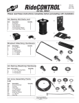
2190
WARNING!
Do not inflate this assembly when it is
unrestricted. The assembly must be restricted by
the suspension or other adequate structure. Do
not inflate beyond 100 P.S.I. Improper use or
over inflation may cause property damage or
severe personal injury.
INSTALLATION INSTRUCTIONS
Congratulations - your new Air Helper Springs are quality
products capable of improving the handling and comfort of your
vehicle. As with all products, proper installation is the key to
obtaining all of the benefits your kit is capable of delivering.
Please take a few minutes to read through the instructions to
identify the components and learn where and how they are used.
It is a good idea to start by comparing the parts in your kit with
the parts list below.
The heart of the Air Helper Spring kit is, of course, the air
helper springs. Remember that the air helper springs must flex
and expand during operation, so be sure that there is enough
clearance to do so without rubbing against any other part of the
vehicle.
Be sure to take all applicable safety precautions during the
installation of the kit. The instructions listed in this brochure
and the illustrations all show the left, or driver’s side of the
vehicle. To install the right side assembly simply follow the same
procedures.
PARTS LIST
AIR SPRING
6781
UPPER BRACKET
5178
LOWER BRACKET
5250
FRAME BRACE (LEFT)
5249
FRAME BRACE (RIGHT)
5248
18 ft. TUBING
0938
3/8"-16 X 4" HEX BOLT
3/8"-16 FLANGED LOCK NUT
3/8"-16 X 3/4" FLANGED HEX BOLT
21-8178
2
2
2
1
1
1
4
8
2
Your kit includes separate inflation valves and air lines for
each air helper spring. This will allow you to level your vehicle
from side to side as well as from front to back. If you would rather
have a single valve inflation system, your dealer can supply the
required "T" fitting.
IMPORTANT!
For your safety and to prevent possible damage to your
vehicle, do not exceed the maximum load recommended by
the vehicle manufacturer (GVWR). Although your Air Helper
Springs are rated at a maximum inflation pressure of 100
psi, this pressure may allow you to carry too great a load on
some vehicles. It is best to have your vehicle weighed once
it is completely loaded and compare that weight to the
maximum allowed. Check your vehicle owner’s manual or
data plate on driver side door for maximum loads listed for
your vehicle.
When inflating your Air Helper Springs, add air pressure in small quantities, checking pressure frequently during inflation. The air spring requires much less air volume
than a tire and, therefore, inflates much quicker.
5/16" FLAT WASHER
J-BOLT
5/16" -18 FLANGED LOCK NUT
HEAT SHIELD
PUSH-TO-CONNECT
INFLATION VALVE
PUSH-TO-CONNECT ELBOW
THERMALSLEEVE
NYLON TIES
12-03
1004
3101
3098
0899
4
8
8
1
2
2
2
7
NCD-6037-2
2190 / 6011
KIT TO FRAME ASSEMBLY
NOTE: Both illustrations are of the left,
or drivers side, of the truck. Refer to
step 3 for the proper lower bracket
alignment.
BRAKE-LINE
BRACKET
BRAKE-LINE / AXLE
VENT TUBE CLIP
FRAME BRACE
F
R
A
M
E
3/8” -16 x 4”
HEX BOLTS
KIT ASSEMBLY
DRILL TWO
7/16” HOLES
3/8” -16
FLANGED
LOCK NUT
UPPER
BRACKET
JOUNCE BUMPER
BRACE
3/8” -16
FLANGED
HEX NUT
AIR
FITTING
AIR
LINE
5/16” -18
FLANGED
HEX NUT
LEAF STACK
J-BOLT
INSTALLATION
LOCATION
5/16” -18
FLANGED
HEX NUT
AIR
SPRING
JOUNCE
PAD
J-BOLT
3/8” -16 x 3/4”
FLANGED HEX BOLT
L
E
E
H
W
F
R
O
N
T
LOWER
BRACKET
FIGURE "A"
AXLE
FRAME RAIL
FRAME
BRACE
AIR SPRING
UPPER
BRACKET
LOWER
BRACKET
J-BOLT
DRIVER'S SIDE
BRAKE
LINE
FRONT
SHOCK
BRACKET
JOUNCE PAD
FIGURE "B"
STEP 1 - PREPARE THE VEHICLE
Remove the positive battery cable. With the vehicle on a solid, level surface
chock the front wheels. Raise the vehicle by the axle and remove the rear wheels.
After the removal of the wheels lower the vehicle so the axle rests on jack stands
rated to support your vehicles weight. This installation assumes that there is no
load in the bed of the truck.
Your vehicle is equipped with rubber jounce bumpers. The bumpers are
attached to the frame directly above the axle. Remove these bumpers by unbolting
from the inside of the frame flange see Figure "C". This bumper will not be reused
with this kit.
The brake line bracket and brake-line/axle vent tube clip will need to be loosened
and removed to allow installation of the frame brace. The brake-line bracket is
attached to the top flange of the frame with two hex bolts. Remove the hex bolts
to allow the brake-line bracket to be moved far enough to facilitate installation of
the frame brace. The brake-line/axle vent tube clip is attached to the top of the upper
frame flange with a plastic pin. Remove the pin with a panel tool or screw driver
see Figure "C". Pull the clip out of the way of the frame brace.
PLASTIC PIN
BRAKE-LINE/
AXLE VENT TUBE
CLIP
FACTORY
BOLTS
F
R
A
M
E
PIN
BRAKE-LINE
BRACKET
JOUNCE
BUMPER
FIGURE "C"
STEP 2 - PRE-ASSEMBLE THE KIT
Pre-assembly will begin with the left (driver's) side of the vehicle. All pictures
depict the installation on the left side of the vehicle unless noted otherwise. Select
one of the air springs and install the push-to-connect air fitting in the top threaded
hole and tighten securely. Tighten the air fitting so as to make contact with the
nylon ring and then tighten 1/4 turn to snug fitting. No thread sealant is needed.
Secure the upper bracket to the air spring using 3/8" -16 flanged lock nuts. Next,
select a lower bracket and secure to the air spring using a 3/8" -16 x 3/4" flanged
hex bolt see Figure "A". Be sure that the lower bracket is attached to the air
spring so that the bracket orientation is perpendicular to the upper bracket. When
the upper bracket of the air spring assembly is attached to the frame rail, the
lower bracket should rest in-line on top of the axle without twisting the air spring
see Figures "A" & "B".
STEP 3 - INSTALL THE ASSEMBLY TO THE VEHICLE
TIE RIGHT PARKING BRAKE-LINE
TO BRAKE-LINE BRACKET ON AXLE
FIGURE "D"
HEAT SHIELD
FIGURE "E"
Insert the left-side frame brace into the frame rail so that it straddles the jounce
bumper brace see Figure "A". Ensure that the frame brace does not pinch any
existing brake, electrical, or fuel lines that may be inside the frame rail. The brakeline bracket and brake-line/axle vent tube clip will have to be held clear to allow
installation of the frame brace.
Place the air spring assembly on top of the jounce bumper pad on top of the
axle housing. Align the air spring over the axle. Slide the upper bracket onto the
frame rail and frame brace. Visually align the holes in the upper bracket with the
slots in the frame brace. It may be necessary to use a rubber mallet to force the upper
bracket onto the frame. Mark the frame with a center punch in the center of the holes
on the upper bracket. Use the upper bracket as a template to drill two 7/16" mounting
holes in the frame rail see Figure "A". Before drilling the holes make sure all
electrical, brake, and fuel lines are cleared from the path of the drill. In order to
prevent any damage to these lines it is recommended that a thin piece of wood be
placed between the frame rail and the existing lines. Attach the upper bracket with
the 3/8"-16 x 4" hex bolts and 3/8" -16 flanged hex nuts see Figures "A" & "B".
With the assembly attached to the frame rail, the next step is to attach the lower
bracket to the jounce pad on the axle housing. Center the lower bracket on the
jounce pad. Use the J-bolts and 5/16" -18 flanged lock nuts to secure the lower
bracket to the jounce pad see Figures "A" & "B". Spin the nuts on as far as possible
by hand. While making sure that the lower bracket stays centered on the jounce
pad, tighten each nut two turns at a time with a wrench, switching to opposite nuts
to ensure that the bracket is mounted evenly on the jounce pad. After the
installation of the left-side assembly is complete, re-attach the brake-line bracket
and brake-line/axle vent tube clip to the frame.
Important: In order for the air spring to function properly, there must be
a minimum of 1/2" of clearance around the air spring. The right-side parking
brake-line must be tied to the brake-line bracket on the axle housing to prevent
it from interfering with the normal operation of the left-side air spring see
Figure "D".
AIR
SPRINGS
AIR HOSE
STEP 4 - INSTALL THE PASSENGER'S SIDE ASSEMBLY
Follow steps 2 - 5 for assembly and installation of the passenger's side
assembly. Note: The use of a heat shield is required on the passenger's side of
the vehicle. The heat shield will mount between the upper bracket and the air helper
spring see Figure "E". Position the shield halfway between the nearest point of
the exhaust pipe to the rubber air spring. Ensure that the heat shield will not interfere
with the normal operation of the air spring or the vehicle's suspension. Do not
position the face of the shield directly over the axle, as it may contact the axle on
full suspension compression.
INFLATION
VALVES
BUMPER
FIGURE "F"
AIR LINE
FLAT WASHER
STEP 5 - INSTALL THE AIR LINE AND INFLATION VALVE
Uncoil the air tubing and cut it in two equal lengths. DO NOT FOLD OR KINK
PUSH-TO-CONNECT
INFLATION VALVE
THE TUBING. Make the cut as square as possible. Insert one end of the tubing
BODY OF
into the push-to-connect elbow fitting installed in the top of the air helper spring
VEHICLE
as far as possible.
Select a location on the vehicle for the air inflation valves. The location can be
HEX NUT
VALVE CAP
on the bumper or the body of the vehicle, as long as it is in a protected location so
the valve will not be damaged, but still maintain accessibility for the air chuck see
FIGURE "G"
Figure "F". Drill a 5/16" hole and install the air inflation valve using two 5/16" flat
washers per valve as supports see Figure "G". Run the tubing from the air helper
spring to the valve, routing it to avoid direct heat from the engine, exhaust pipe, and away from sharp edges. Thermal sleeves
have been provided for these conditions. The air line tubing should not be bent or curved sharply as it may buckle. Secure the
tubing in place with the nylon ties provided. Push the end of the air line tubing into the inflation valve see Figure "G".
STEP 6 - CHECK THE AIR SYSTEM
Once the inflation valves are installed, inflate the air helper springs to 70 psi and check the fittings for air leaks. Using a spray
bottle, apply a solution of soap and water to the fittings. If a leak is detected at a airline tubing connection then check to make
sure that the airline tube is cut as square as possible and that it is pushed completely into the fitting. The airline tubing can easily
be removed from the fittings by exhausting all the pressure in the air springs and then pushing the collar towards the body of the
fitting and then, with a pull, remove the airline tubing. Reinstall the tubing and reinflate the air springs and check for leaks as noted
above. If a leak is detected where the air fitting screws into the spring, just screw the air fitting into the air spring until the leak
stops.
This now completes the installation. Install the wheels and torque the lug nuts to the manufacturer's specification. Raise
the vehicle by the axle and remove the jack stands. Lower the vehicle to the ground. Reattach the negative battery cable and
remove the wheel chocks from the front wheels. Before proceeding, check once again to be sure you have proper clearance
around the air springs. With a load on your vehicle and the air helper springs inflated, you must have at least 1/2" clearance around
the air springs. As a general rule, the air helper springs will support approximately 50 lbs. of load for each psi of inflation pressure
(per pair). For example, 50 psi of inflation pressure will support a load of 2500 lbs. per pair of air helper springs. FOR BEST
RIDE use only enough air pressure in the air helper springs to level the vehicle when viewed from the side (front to rear). This
amount will vary depending on the load, location of load, condition of existing suspension and personal preference.
NOTE:
Too much air pressure in the air helper springs will result in a firmer ride, while too little air pressure will allow the air helper spring
to bottom out over rough conditions. Too little air pressure will also not provide the possible improvement in handling. TO
PREVENT POSSIBLE DAMAGE, MAINTAIN A MINIMUM OF 5 P.S.I. IN THE AIR HELPER SPRINGS AT ALL TIMES.
NOTE:
Once the air helper springs are installed, it is recommended that the vehicle not be lifted by the frame, as overextension may occur, resulting in damage to the air helper springs. However, should it become necessary to raise the vehicle
by the frame, deflate both air helper springs completely.