1
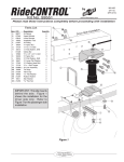
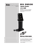
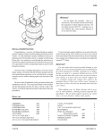
MN-461
(021108)
ECR 7136
Kit No. 59537
Please read these instructions completely before proceeding with installation
Air Spring Kit Parts List
Item
A
B
C
D
E
Description
Air Sleeves
Upper Brackets
Lower Brackets
Jounce Bumper Spacer
LowProfileElbowFitting
Quantity
2
2
2
2
2
B
A
C
D
E
F
Bracket Attaching Hardware
Item
F
G
H
I
J
K
Description
3
/8 “-16 U-Bolts
Clamp Bar
3
/8 “NylockNuts
3
/8 “FlatWashers
3
/8 “x1”WHST
3
/8 “ x 1” HHCS
G
Quantity
2
2
6
6
6
2
H
I
J
K
Air Spring Attaching Hardware
Item Description
L
M
N
/2 “ x 7/8 “ Hex Head Bolts
3
/4 “ Hex Jam Nut
1
/2”FlatWashers
1
Quantity
2
2
2
M
L
N
AirLineAssemblyParts
List
Item
AA
BB
CC
DD
EE
FF
GG
HH
Description
AirLineAssembly
Tie Strap
Valve Caps
5
/16”FlatWasher
RubberWasher
SmallStarWasher
5
/16” Hex Nut
Hose Clip
CC
AA
Quantity
1
6
2
2
2
2
4
4
DD
GG
BB
Technical Support
1-800-248-0892
Ext. 2
EE
HH
FF
II
Tools Needed
HoseCutter,RazorBlade,orSharpKnife
HoistorFloorJacks
SafetyStands
SafetyGlasses
AirCompressor,orCompressedAirSource
SprayBottlewithDishSoap/WaterSolution
Standardandmetricopenendorboxwrenches
Ratchet with 3/8”, 1/2”,&9/16” deep well sockets
5
/16”drillbit(verysharp)
7
/16”&9/16” Nut Drivers
HeavyDutyDrill
TorqueWrench
IMPORTANT:Yourvehiclemaybeequippedwitharearbrakeproportioningvalve.Anytypeofloadassist
productcouldaffectbrakeperformance.Werecommendthatyoucheckwithyourdealerbeforeinstalling
thistypeofproduct.IfyourvehicleDOESNOThavearearbrakeproportioningvalveorisequippedwithan
anti-locktypebrakesystem,installationofaloadassistproductwillhaveNOEFFECTONBRAKESYSTEM
PERFORMANCE.
IMPORTANT: Failuretomaintaincorrectminimumpressure(orpressureproportionaltoload),bottoming
out,overextension,orrubbingagainstanothercomponentwillvoidthewarranty.
DANGER:Compressedaircancauseinjuryanddamagetothevehicleandpartsifitisnothandledproperly.
Foryoursafety,donottrytoinflatetheairspringsuntiltheyhavebeenproperlysecuredtothevehicle.
I.GettingStarted
1. Determine the Normal Ride Height. The Normal Ride
Height is the distance between the bottom edge of the
wheel-well and the center of the hub with the vehicle
in the “as delivered” condition.Insomecases,Normal
RideHeightisnotperfectlylevel.
a. Removeunusualloadsandexamineyourvehiclefrom
thesidetoensureitisonalevelsurface(Figure1).
Figure 1
b. If necessary (in cases where your leaf springs are
saggingbadly),useajacktoraisetherearendsothat
the vehicle achieves the original “as delivered” ride
height.
2. Measurethedistancebetweenthecenterofthehuband
thebottomedgeofthewheelwell(Figure2).Thisisthe
NormalRideHeight.Enterthemeasurementbelow:
Figure 2
NORMAL
RIDEHEIGHT:__________inches
Technical Support
1-800-248-0892
Ext. 2
II.AssemblingtheAirSpringUnit
1. Install90degreeairswivelfitting(E)tothetopoftheair
spring.Useanopenendwrenchbeingcarefultotighten
onthemetalhexnutonly.Tighten1and1/2turns(Figure
3).Donotovertighten.
NOTE: This fitting is precoated with sealant.
2. Set upper bracket (B) over the fitting and thread post
(Figure4).Positiontheelbowtowardsthefrontorrearof
the vehicle depending on which direction will allow easier
accessfortheairline.
Figure 3
3. Threadnylonnut(M)ontothethreadpost,makingsure
thattheflatsideisup(Figure5).
4. Tightenthenylonnut.Handtightissufficient.
IMPORTANT: Ensure that the bracket is tight and flat
to the roll plate on both sides.
5. Looselyattachthelowerbracket(E)tothebottomofthe
air spring with 1/2”flatwasher(N)and1/2” Hex Head Cap
Screw(L).SeeFigure6.
Figure 4
Upper Bracket
3/4" Nylon Nut
Nylon nut must be threaded
on the thread post with the
curved edge toward the
sleeve.
Air Spring
Figure 5
Figure 6
Technical Support
1-800-248-0892
Ext. 2
III.InstallingtheJounceSpacer
Jounce
Strike Plate
Figure 7
1. Forheavyloadusage,werecommendinstallingajounce
bumperstrikeplatespacer(D)underthestockstrikeplate
(Figure7).
2. Position the strike plate spacer (D) flush with the back
bottom edge of the stock strike plate and mark the
mountingholelocationusingapencilormarker(Figure
8).
3. Centerpunchanddrilla3/8”holeinthestockstrikeplate.
NOTE: In order to gain more accessibility for drilling
the mounting hole, it may be necessary to drop the
axle. Keep safety in mind and use safety stands if
needed.
Figure 8
4. Boltthestrikeplatespacertostockstrikeplateusinga3/8”
bolt(K),twowashers(I),andanylocknut(H).SeeFigure
10.Torqueto16ft-lbs.
IV.MountingtheLowerBracket
IMPORTANT: If the axle was dropped to install the jounce
strike plate spacer, it will be necessary to raise it back to
the normal ride height recorded on page 2.
Figure 9
1. Withthevehicleatnormalrideheight,withthehookendof
thelowerbracketoverthefactoryU-bolt,settheairspring
assembly on the leaf spring forward of the axle (Figure
11).
2. SecurethelowerbrackettotheleafspringusingU-bolt
(F),clampbar(G),flatwasher(I),andnylocknut(H).See
Figure12.Tightento16ft-lbs.
Figure 10
Figure 11
Technical Support
1-800-248-0892
Ext. 2
V.LocatingtheUpperBracket
1. Theupperbracketmustbeparallelandperpendiculartothe
lowerbracketasshownintheillustrationinFigure13.
2. Aligntheupperbracketsothattheshortlegoftheupper
brackettouchesthebottomoftheframerail(Figure14).
3. Usingtheupperbracketasatemplate,centerpunchone
hole(Figure15).AweldingclamporC-clampmayassist
inholdingtheupperbrackettotheframe.
Figure 12
NOTE: It is necessary to use at least three of the five
pre-drilled holes in the upper bracket for mounting.Any
combinationofthethreeispermissible.
4. CAUTION: Before drilling, be sure to check the back
side of the frame rail for brake lines, gas lines, or
electrical lines that may be in the way. It is necessary
to move any interfering lines prior to drilling.
Figure 13
5. Drillone 5/16”holeandinstalloneWHST(J).SeeFigure
16.Tightento15ft-lbs.
IMPORTANT: Check again to make sure that the upper
and lower brackets are parallel and perpendicular to
each other (Figure 13).
6. Centerpunch and drill remaining two holes and install
the WHST (J). Again, torque to 15 ft-lbs. Do not over
tighten.
Fitthebottom
oftheupper
brackettightto
theframerail
Frame
Rail
Upper
Bracket
Figure 14
VI.InstallingtheOtherSide
1. Installtheminimum/maximumairpressuredecalinahighly
visiblelocation.
2. Repeatentireinstallationprocedureforremainingside.
3. ContinuewithsectionVII,InstallingtheAirLines.
Technical Support
1-800-248-0892
Ext. 2
Figure 15
Figure 16
VII.InstallingtheAirLines
1. Choose a convenient location for mounting the inflation
valves.Popularlocationsfortheinflationvalveare:
a. Thewheelwellflanges.
b. Licenseplaterecessinbumper.
c. Underthegascapaccessdoor.
d. Throughlicenseplateitself.
Figure 17
Good cut – clean and
square
Badcut–flattened
NOTE: What ever the chosen location is, make sure
there is enough clearance around the inflation valves
for an air chuck.
2.Drilla5/16 “holetoinstalltheinflationvalves.
3. Cuttheairlineassembly(AA)intwoequallengths(Figure
17).
Figure 18a
Figure 18b
Figure 19
VehicleBodyor
Bumper
/16” Nut
StarWasher
5
RubberWasher
FlatWasher
5
/16” Nut
CAUTION: When cutting or trimming the air line, use a
hose cutter (Air Lift P/N 10530), a razor blade or a sharp
knife. A clean, square cut will ensure against leaks.
(Figure 18a). Do not use wire cutters or scissors to
cut the air line. These tools may flatten or crimp the
air line, causing it to leak around the O-ring seal inside
the elbow fitting (Figure 18b).
4. Placea 5/16 “nut(GG)andastarwasher(FF)ontheair
valve.Leaveenoughoftheinflationvalveinfrontofthenut
toextendthroughtheholeandhaveroomfortherubber
washer (EE), flat washer (DD), and 5/16 “ nut (GG) and
cap(CC).Thereshouldbeenoughvalveexposedafter
installation-approximately1/2 “-toeasilyapplyapressure
gaugeoranairchuck(Figure19).
5. Push the inflation valve through the hole and use the
rubberwasher(EE),flatwasher(DD),andanother 5/16 “
nut(GG)tosecureitinplace.Tightenthenutstosecure
theassemblyinplace(Figure20).
Figure 20
Technical Support
1-800-248-0892
Ext. 2
6. Routetheairlinealongtheframetotheairfittingontheair
spring.Keepatleast6”ofclearancebetweentheairline
andheatsources,suchastheexhaustpipes,muffler,or
catalyticconverter.Avoidsharpbendsandedges.Use
theplastictiestraps(BB)tosecuretheairlinetofixed,
non-movingpointsalongthechassis(Figure21).Besure
thatthetiestrapsaretight,butdonotpinchtheairline.
Wheretherearenoholestosecurethestrapsto,usethe
airlineclip(HH)andselftapper(II)tosecuretheairlineto
theframe(Figure22).Leaveatleast2”ofslacktoallow
foranymovementthatmightpullontheairline.
Figure 21
7. Cutoffairlineleavingapproximately12”ofextraairline.
Acleansquarecutwillensureagainstleaks.Insertthe
airlineintotheairfitting.Thisisapushtoconnectfitting.
Simplypushtheairlineintothe90°swivelfittinguntilit
bottomsout(9/16”ofairlineshouldbeinthefitting).
Figure 22
Figure 23
Technical Support
1-800-248-0892
Ext. 2
VIII.AligningtheAirSprings
1. IMPORTANT:Withthebottomoftheairspringstillloose,
inflatetheairspringtoapproximately10p.s.i.Usethe
slottedadjustmentinthelowerbrackettocorrectlyalign
theairspringbetweentheupperandlowerbracket.This
canbeaccomplishedbytappingitinboardoroutboardfor
properalignment.Thereshouldbeasymmetricalcushion
of air around the base of the air spring when correctly
positioned.Figure24representsamisalignedairspring.
Figure25showsaproperlyalignedairspring.
Figure 24
2. When aligned, tighten the lower end by holding the air
spring and turning the bolt with a 3/4” open end wrench
(Figure26).Snug(10ft-lbs)willbesufficientandwillalso
preventstrippingthethreads.Do not attempt to hold the
air spring with any type of tool.
3. Figure27showsthecompletedinstallation.
Figure 25
Figure 26
Figure 27
Technical Support
1-800-248-0892
Ext. 2
IX.CheckingforLeaks
1. Inflatetheairspringto60p.s.i.
2. Sprayallconnectionsandtheinflationvalveswithasolution
of1/5liquiddishsoapand4/5watertocheckforleaks(Figure
28).Youshouldbeabletospotleakseasilybylookingfor
bubblesinthesoapywater.
3.Afterthetest,deflatethespringstothe minimumpressure
requiredtorestoretheNormalRideHeight,butnotless
than10p.s.i.
Figure 28
4. IMPORTANT:Checktheairpressureagainafter24hours.
A2to4p.s.i. lossafterinitialinstallationisnormal.Retest
forleaksifthelossismorethan5lbs.
Air Line
Connection
SwivelFitting
Threaded
Connection
Collar
X.FixingLeaks
1. Ifthereisaproblemwiththeswivelfitting,then:
a. Check the air line connection by deflating the spring
andremovingthelinebypullingthecollaragainstthe
fittingandpullingfirmlyontheairline.Trim1”offthe
endoftheairline.Besurethecutiscleanandsquare.
Reinserttheairlineintothepush-to-connectfitting.See
Figure29.
b. Checkthethreadedconnectionbytighteningtheswivel
fitting another 1/2 turn. If it still leaks, deflate the air
spring,removethefitting,andre-coatthethreadswith
threadsealant.Reinstallbyhandtighteningasmuch
aspossible,thenuseawrenchforanadditionaltwo
turns.SeeFigure29.
Figure 29
Valve
Core
Barbed
Air Line
Connection
2. Ifthereisaproblemwiththeinflationvalve,then:
a. Checkthevalvecorebytighteningtheitwithavalve
coretool.
b. Checktheairlineconnection(Figure30)byremoving
the air line from the barbed type fitting. CAUTION:
Do not cut it off. As this will usually nick the barb
and render the fitting useless. Cutairlineoffafew
inchesinfrontofthefittinganduseapairofpliersor
vise-gripstopull/twisttheairlineoffthefitting.
3. If the preceding steps have not resolved the problem,
call Air Lift Technical Service at 1-800-248-0892 for
assistance.
Technical Support
1-800-248-0892
Ext. 2
Figure 30
XI.TroubleshootingGuide
Problems maintaining air pressure, without on-board
compressor.
1.Leaktesttheairlineconnectionsandthreadedconnection
oftheelbowintotheairspring(Figure28).SeeSection
Xtorepair.
Figure 31
2. Leak test the inflation valve for leaks at the air line
connectionordirtordebrisinthevalvecore(Figure31).
SeeSectionXforrepair.
3. Inspectairlinestobesureitisnotpinched.Tiestrapsmay
betootight.Loosenorreplacestrap.Replaceleaking
components(Figure32).
4. Inspectairlineforholesandcracks(Figure33).Replace
asneeded.
Figure 32
5. A kink or fold in the air line (Figure 34). Reroute as
needed.
You have now tested for all of the most probable leak
conditions that can be easily fixed. At this point the
problem is most likely a failed air spring - either a factory
defect or an operating problem. Please call Air Lift at 1-800248-0892 for assistance or a replacement air spring.
Figure 33
Figure 34
Technical Support
1-800-248-0892
Ext. 2
XI.Checklist
You can protect your warranty on this product and prevent unnecessary wear by ensuring the following
checks have been made:
SectionI–Installation(Tobecompletedbytheinstaller):
1. ClearanceTest-Inflatetheairspringsto60p.s.i.andensurethereisatleast1/2 “ clearance around
eachsleevefromanythingthatmightrubagainstthem.Besuretocheckthetire,brakedrum,frame,
shockabsorbersandbrakecables.
2. LeakTestBeforeRoadTest–Inflatetheairspringsto60p.s.i.,checkallconnectionsforleakswith
asoapywatersolution.Seepages9and10ofthemanualfortipsonhowtospotleaks.Allleaks
mustbeeliminatedbeforethevehicleisroadtested.
3. HeatTest–Besurethereissufficientclearancefromheatsources-atleast6”forairspringsandair
lines.Ifaheatshieldwasincludedinthekit-installit.Ifthereisnoheatshield,butoneisrequired,
call1-800-248-0892.
4. FastenerTest–Recheckallboltsforpropertorque.
TorqueGuide:
WHST U-boltLockNuts LowerBoltforAirSpring 15ft-lbs
16ft-lbs
10ft-lbs
5. RoadTest–Thevehicleshouldberoadtestedaftertheprecedingtests.Inflatethespringsto25
p.s.i.(50p.s.i.ifvehicleisloaded).Drivethevehicle10milesandrecheckforclearance,loose
fastenersand/orairleaks.
6. OperatingInstructions–Ifprofessionallyinstalled,theinstallershouldreviewtheoperatinginstructions
onpage12withtheowner.Besuretoprovidetheownerwithallofthepaperworkthatcamewith
thekit.
SectionII-PostInstallationChecklist(Tobecompletedbytheowner):
1. OvernightLeakdownTest–Recheckairpressureaftervehiclehasbeenusedfor24hours.If
pressurehasdroppedmorethan5p.s.i.then,youhavealeakthatmustbefixed.Eitherfixthe
leakyourself(seepages9and10)orreturntotheinstallerforservice.
2. AirPressureRequirements–Iunderstandthattheairpressurerequirementsofmyairspring
systemareasfollows:
Minimum___________Maximum___________
IalsounderstandthatImustinflatetheairspringsuntiltheRideHeightmeasurementthatwas
recordedonpage2hasbeenrestored.Regardlessofload,theairpressureshouldalwaysbe
adjustedsothattheRideHeightismaintainedatalltimes.
3. ThirtyDayor500MileTest.IunderstandthatImustrechecktheairspringsystemafter30
daysor500miles,whichevercomesfirst.Ifanypartshowssignsofrubbingorabrasion,the
sourceshouldbeidentifiedandmoved,ifpossible.Ifit isnotpossibletorelocatethecauseof
theabrasion,theairspringmayneedtoberemounted.Ifprofessionallyinstalled,theinstaller
shouldbeconsulted.Checkallfastenersfortightness.
Technical Support
1-800-248-0892
Ext. 2
XII.MaintenanceandOperations
Minimum Air Pressure
Maximum Air Pressure
5p.s.i.
100p.s.i.
Failure to maintain correct minimum pressure (or pressure proportional to
load), bottoming out, over-extension, or rubbing against another component
will void the warranty.
Byfollowingthesesteps,vehicleownerswillobtainthelongestlifeandbestresultsfromtheirair
springs.
1. Checktheairpressureweekly.
2. AlwaysmaintainNormalRideHeight.Neverinflatebeyond100p.s.i.
3. Ifyoudevelopanairleakinthesystem,useasoapywatersolutiontocheckallairlineconnectionsand
theinflationvalvecorebeforedeflatingandremovingtheairspring.(Seepage9.)
4. Whenincreasing load,alwaysadjustthe air pressure to maintain the Normal Ride Height. Increase
ordecreasepressurefromthesystemasnecessarytoattainNormalRideHeightforoptimalrideand
handling.Rememberthatloadscarriedbehindtheaxle(includingtongueloads)requiremoreleveling
force(pressure)thanthosecarrieddirectlyovertheaxle.
5. IMPORTANT:Foryoursafetyandtopreventpossibledamagetoyourvehicle,do not exceed maximum
Gross Vehicle Weight Rating (GVWR), as indicated by the vehicle manufacturer.Althoughyour
airspringsareratedatamaximuminflationpressureof100p.s.i.Theairpressureactuallyneeded
isdependantonyourloadandGVWR,whichmaybelessthan100p.s.i.Checkyourvehicleowners
manualanddonotexceedthemaximumloadlistedforyourvehicle.
6. Alwaysaddairtospringsinsmallquantities,checkingthepressurefrequently.Sleevesrequirelessair
volumethanatireandinflatequickly.
7. Should it become necessary to raise the vehicle by the frame, make sure the system is at minimum
pressure (5 p.s.i.) to reduce the tension on the suspension/brake components. Use of on–board
leveling systems do not require deflation or disconnection.
Thank you for purchasing Air Lift Products
MailingAddress:
AIRLIFTCOMPANY
P.O.Box80167
Lansing,MI48908-0167
StreetAddress:
AIRLIFTCOMPANY
2727SnowRd.
Lansing,MI48917
LocalPhone:(517)322-2144
Fax:(517)322-0240
ForTechnicalAssistancecall1-800-248-0892
“The Choice of the Professional Installer”
Technical Support
1-800-248-0892
Ext. 2
Printed in the USA