1
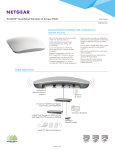
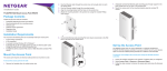
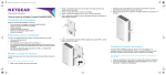
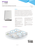
ProSAFE Wireless Controller WC7600 Package Contents The package contains the following items: • • • • • • ProSAFE® Wireless Controller WC7600 AC power cable Straight-through Category 5 Ethernet cable Rack-mount kit Rubber feet (4) with adhesive backing Installation guide WARNING: DO NOT stack equipment, or place equipment in tight spaces or in drawers. Be sure that your equipment is surrounded by at least 2 inches (5 cm) of air space. 2 Meet Your Wireless Controller Before you install your wireless controller, familiarize yourself with its LEDs, buttons, and ports. Front Panel Digital access point counter Slots and LEDs for optional SFP GBIC modules LED Mode: Green= Link at 10G, Blink Green=10G Active, Yellow=Link at 1G, Blink Yellow=1G Active ID Power LED Mode: Left LED: Green=Link at 1G E, Yellow=Link at 10/100M Right LED:Green=Link, Green Blink=Active Status Fan Stack Master USB Console 9600,N,8,1 Reset USB port Reset button Ethernet port and LEDs LEDs (top to bottom): Power, Status, Fan, Stack Master 3 COM port Rear Panel Power Status LED Power input 4 Set Up the Wireless Controller To set up the wireless controller: 1. Configure your computer with a static IP address of 192.168.0.210 and a subnet mask of 255.255.255.0. 2. Connect one end of the supplied Ethernet cable to the Ethernet port on your computer and the other end to the Ethernet port on the front panel of the wireless controller. 3. Connect the supplied power cord from the wireless controller to an AC power outlet. 4. Verify that the following LEDs on the front panel are lit: LED Description Power The green Power LED is lit. If this LED is not lit, check the connections and check to see if the power outlet is controlled by a wall switch that is turned off. Status The Status LED is lit yellow while the wireless controller is initializing. After approximately two minutes, when the wireless controller has completed its initialization, the Status LED turns green. 5 LED Description Fan The green Fan LED is lit, indicating that the fans are functioning correctly. Ethernet The right Ethernet port LED is lit green for a 1000 Mbps port connection or yellow for a 100 or 10 Mbps connection. 6 Access the Wireless Controller To access the wireless controller: 1. On your computer, open a browser. In the address field, type http://192.168.0.250. The wireless controller’s login screen displays: 2. Enter admin for the user name and password for the password, both in lowercase letters. 3. Click the Login button. 7 The wireless controller’s web management interface displays. Configure the Basic Settings To configure the basic settings: 1. From the main navigation menu, select Configuration > System > General. 2. Enter a name for the wireless controller. 3. Select the country in which the wireless controller is used. 4. Click the Apply button. 5. Select Configuration > System > Time. 8 6. 7. 8. 9. 10. Select the time zone in which the wireless controller is used. (Optional) Configure the NTP settings. Click the Apply button. Select Configuration > System > IP/VLAN. Enter the IP settings for your network and the VLANs that you want to assign to the wireless controller. Note: For large deployments, NETGEAR recommends that the wireless controller and access points are in separate VLANs to ensure uninterrupted connectivity between the wireless controller and the access points. Note: Clear the Untagged VLAN check box only if the hubs and switches in your network support the VLAN (802.1Q) standard. Change the untagged VLAN value only if the hubs and switches in your network support the VLAN (802.1Q) standard. 11. Click the Apply button. The connection to the wireless controller is terminated because you have changed its IP address. 12. Reconfigure your computer with an IP address and subnet mask that is in the same IP subnet as the wireless controller. Use the new IP address of the wireless controller to log in again. 9 13. Select Configuration > System > DHCP Server. The Discovery Wizard (see Discover Access Points) requires a DHCP server to discover the access points. If you already have a DHCP server in your network, disable the DHCP server on the wireless controller. Otherwise, configure the DHCP settings for the DHCP server on the wireless controller. 14. Click Apply. 15. Decide whether to use the basic profile group (suitable for a small WLAN) or one or more advanced profile groups (suitable for a large WLAN): • Basic. Allows up to eight profiles (16 for dual-band access points), each of which has its own SSID, security, MAC ACL, rate-limiting settings, WMM settings, and so on. a. Select Configuration > Profile > Basic > Radio. b. Configure one or more profiles, each with its SSID and security settings. • c. Click the Apply button. Advanced. Allows up to eight profile groups. Each group includes all the settings that are required to configure a fully functional access point with up to eight security profiles (16 for dual-band access points). a. Select Configuration > Profile > Advanced > Radio. 10 b. Configure one or more profile groups, each with one or more profiles that have their own SSID and security settings. c. Click the Apply button. Note: For extensive information about the configuration options of the wireless controller, including profile groups, see the reference manual. Deploy the Wireless Controller To deploy the wireless controller: 1. Disconnect the power cord from the wireless controller. 2. Disconnect the wireless controller from the computer and place it where you intend to deploy it. 3. Connect one end of an Ethernet cable to a LAN port on a router or switch in your network and the other end to the Ethernet port on the front panel of the wireless controller. 4. Reconnect the power cord from the wireless controller to an AC power outlet. The LEDs light as described in Setup the Wireless Controller. 11 Discover Access Points The wireless controller manages selected NETGEAR access points. For a list of supported NETGEAR access points, visit the NETGEAR support site. Before attempting to discover access points, familiarize yourself with the access point LEDs: LED Description Power The green Power LED blinks when the access point is first powered on and then lights solid green. If after 30 seconds the Power LED is off or is still blinking, check the connections and check to see if the power outlet is controlled by a wall switch that is turned off. Active The Active LED blinks when the access point detects network traffic. LAN Green. 1000 Mbps connection speed. Amber. 10/100 Mbps connection speed. Off. No link detected. 12 LED Description 2.4 Ghz 2.4 Ghz traffic on the WLAN. 5 Ghz 5 Ghz traffic on the WLAN. The Discovery Wizard can discover access points that are either in factory default state or already deployed and running. For the Discovery Wizard to discover access points across a Layer 2 network, Layer 3 network (behind a router), or remote access points, the following requirements apply: • • Your network must have a DHCP server that has option 43 enabled with the IP address of the wireless controller, or the DHCP server on the wireless controller must be accessible to all access points. Each access point must have an IP address. Each access point must have SNMP and SSH enabled (which is the default). UDP port number 7890 must be unblocked by your firewall. To discover access points: • • 1. Access the wireless controller at the network IP address that you configured (see Configure the Basic Settings). 2. Select Access Point > Discovery > Discovery Wizard. 13 3. Follow the steps onscreen to discover the access points and review the discovery results. 4. Select Access Point > Discovery > Managed AP List. Add the access points that you want to be managed by the wireless controller to the Managed AP List. While the access points are converted from standalone mode to managed mode, the following occurs: • The wireless controller pushes management firmware onto the access points. • The access points become DHCP clients and receive an IP address from either the DHCP server in your network or the DHCP server on the wireless controller. • The profiles that you have configured on the wireless controller are pushed onto the access points. Note: For extensive information about the Discovery Wizard and the discovery process, see the reference manual. Troubleshooting Tips You cannot access the wireless controller at its default IP address (192.168.0.250). Do the following: • Confirm that the computer is connected to the wireless controller. 14 • • You might not have restarted the computer with the wireless controller to have TCP/IP changes take effect. Restart the computer. The computer might be set to enable NetBIOS over TCP/IP. Check that TCP/IP is set to use a static IP address of 192.168.0.210 and a subnet mask of 255.255.255.0. (The default TCP/IP setting for Windows is to obtain an IP address automatically.) Restart the computer. After initial configuration, you cannot access the wireless controller at its network address. Do the following: • • • Use the ping command to verify the connection. Verify that the computer and wireless controller are on the same VLAN. Some of the wireless controller’s default settings might not work with your network. Check the wireless controller’s default settings against the configuration of other devices in your network. 15 Support Thank you for selecting NETGEAR products. After installing your device, locate the serial number on the label of your product and use it to register your product at https://my.netgear.com. You must register your product before you can use NETGEAR telephone support. NETGEAR recommends registering your product through the NETGEAR website. For product updates and web support, visit http://support.netgear.com. NETGEAR recommends that you use only the official NETGEAR support resources. You can contact NETGEAR tech support representatives via chat, email or phone support at http://support.netgear.com/general/contact/default.aspx. Trademarks NETGEAR, the NETGEAR logo, and Connect with Innovation are trademarks and/or registered trademarks of NETGEAR, Inc. and/or its subsidiaries in the United States and/or other countries. Information is subject to change without notice. © NETGEAR, Inc. All rights reserved. Compliance For the current EU Declaration of Conformity, visit http://support.netgear.com/app/answers/detail/a_id/11621/. For regulatory compliance information, visit http://www.netgear.com/about/ regulatory/ NETGEAR, Inc. 350 East Plumeria Drive San Jose, CA 95134 USA November 2013