1
9.
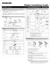
Place the attached cable clamp at an appropriate
location at the back side of the server switch unit and
then fix the operation panel connection cable so that it
will not loosen.
Adjust the cable length
using the cable clamp.
CABLE CONNECTION
5.
The server switch unit is connected with
a server through the K410-118 or
K410-119 cable sold separately.
Fix the cables to the rack with the attached tie
wraps.
6.
The K410-118 cable has a USB connector and a
LCD connector on one end, and D-Sub 15-pin
connector on the other end. The K410-119 cable
has two PS/2 connectors (for keyboard and for
mouse, distinguished by different colors and icons)
and a LCD connector on one end and D-Sub 15-pin
connector on the other end.
After confirming that all the connections are
properly in place, power ON the servers
sequentially.
Select each of the servers to confirm that it has
is started normally and is set correctly.
7.
If the keyboard, mouse, and/or display monitor
are not set correctly, set and start each device
again.
5
Console panel connection cable
Use the dedicated cables listed below to connect
the server switch unit with the server. (Refer to
User's Guide for detail).
This portion should not be slackened.
DESKTOP INSTALLATION ON THE
SERVER SWITCH UNIT
SIMPLEX
CONNECTION -CONNECTING
WITH EIGHT OR LESS SERVERS
Take the following steps to connect cables.
Attach four rubber feet (shock absorber) to the
bottom of the server switch unit when installing for
desktop use, as shown in the figure below.
1.
Connect seven servers to the ports 1 through
7 of the master server switch unit according
to the procedures in "SIMPLEX
CONNECTION -CONNECTING WITH
EIGHT OR LESS SERVERS" described
earlier(Connection (1), (2) in the figure
above.).
Power cords for the server switch unit, the
servers, and the console must be connected
later.
2.
Connect the eighth port of the master server
switch unit to the Keyboard, Mouse, and
Console connectors (console port) of the
slave unit using the dedicated cable
(K410-119(1A)), connecting the slave side
first(Connection (3), (4) in the figure above.).
3.
Connect the remaining eight servers to the
slave server switch unit according to the
procedures in "SIMPLEX CONNECTION
-CONNECTING WITH EIGHT OR LESS
SERVERS" described earlier(Connection (5),
(6) in the figure above.).
4.
After completing the connections of the
server switch unit with the servers, connect
the keyboard, mouse, and display unit to the
Keyboard, MOUSE, and Console connectors
of the master server switch unit(Connection
(7) in the figure above.).
5.
Finally, connect the power cords of the
servers and the display unit and the Power
cord of the server switch unit to the Power
outlet(Connection (8) in the figure above.).
6.
Fix the dedicated cables and Power cords
with the attached tie wraps.
7.
After confirming that all the connections are
properly in place, power ON the servers
sequentially.
8.
If the keyboard, mouse, and/or display
monitor are not set correctly, set and start
each device again.
CASCADE CONNECTION -CONNECTING
WITH NINE OR MORE SERVERS
You can add N8191-10F server switch unit by
using the dedicated connection cable (K410-119
(1A)) to each server port of the server switch unit
or N8143-69 console unit. Such the connection is
called cascade connection.
With eight N8191-10F server switches in cascade
connection, you can select a console from up to
64 servers. In cascade connection, the
installation area can be greatly reduced since it
requires only one console.
The N8191-10F server switch unit in which the
console is connected is called the "master", and
the N8191-10F server switch units connected to
each port of the master unit are called "slaves".
Rear panel side
1.
Front panel side
Connect the keyboard/mouse and display
connectors of the first server through the
dedicated cable (K410-118 or K410-119) to
the server switch unit, connecting first the
server switch unit side, then the server side.
((1), (2) in the figure above).
2.
Connect servers two to eight as necessary.
((1), (2) in the figure above).
3.
When all servers are connected to the server
switch unit, connect the keyboard, mouse,
and the display units to the KB, MOUSE, and
CONSOLE connectors. ((3) in the figure
above.)
4.
Finally, connect the power cords of the
servers and display unit and the AC cord of
the server switch unit into the AC outlet. ((4) in
the figure above)
Shock absorbers
A sample construction is illustrated shown below:
the server switch unit is installed in a rack and 15
servers are connected in the cascade.