1
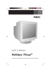
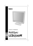
USER'S MANUAL
MultiSync
FP1355
®
™
To learn about other special offers, register online at www.necmitsubishi.com/productregistration
FP1355.wpc
1
1/19/01, 1:20 PM
Index
Warning .................................................................................................. 1
Contents ............................................................................................... 2
Quick Start ........................................................................................... 3
Controls ................................................................................................ 5
Recommended Use ............................................................................. 9
Specifications ..................................................................................... 11
Features .............................................................................................. 12
Troubleshooting ................................................................................. 13
References ..........................................................................................14
Limited Warranty .............................................................................. 15
TCO’99 .................................................................................................. 16
Avertissement .................................................................................... 21
Contenu .............................................................................................. 22
Mise en marche rapide .................................................................... 23
Commandes ....................................................................................... 25
Usage recommandé .......................................................................... 29
Fiche technique ................................................................................. 31
Fonctions ............................................................................................ 32
Dépannage ......................................................................................... 33
Références ......................................................................................... 34
Garantie limitée ................................................................................ 35
TCO’99 ................................................................................................. 36
Warnung ..............................................................................................41
Lieferumfang ..................................................................................... 42
Quick Start ........................................................................................ 43
Bedienungselemente ....................................................................... 45
Empfehlungen für die Verwendung .............................................. 59
Technische Daten .............................................................................. 51
Funktionen ......................................................................................... 52
Fehlerbehebung ................................................................................ 53
Verweise ............................................................................................. 54
Beschränkte Gewährleistung......................................................... 55
TCO’99 ................................................................................................. 56
FP1355.wpc
2
1/19/01, 1:20 PM
WARNING
TO PREVENT FIRE OR SHOCK HAZARDS, DO NOT EXPOSE THIS UNIT TO RAIN OR MOISTURE. ALSO, DO NOT USE
THIS UNIT'S POLARIZED PLUG WITH AN EXTENSION CORD RECEPTACLE OR OTHER OUTLETS UNLESS THE PRONGS
CAN BE FULLY INSERTED.
REFRAIN FROM OPENING THE CABINET AS THERE ARE HIGH VOLTAGE COMPONENTS INSIDE. REFER SERVICING
TO QUALIFIED SERVICE PERSONNEL.
CAUTION
RISK OF ELECTRIC SHOCK • DO NOT OPEN
CAUTION: TO REDUCE THE RISK OF ELECTRIC SHOCK, DO NOT REMOVE COVER (OR BACK). NO USER
SERVICEABLE PARTS INSIDE. REFER SERVICING TO QUALIFIED SERVICE PERSONNEL.
This symbol warns user that uninsulated voltage within the unit may have sufficient magnitude to cause
electric shock. Therefore, it is dangerous to make any kind of contact with any part inside this unit.
This symbol alerts the user that important literature concerning the operation and maintenance of this
unit has been included. Therefore, it should be read carefully in order to avoid any problems.
Canadian Department of Communications Compliance Statement
DOC: This Class B digital apparatus meets all requirements of the Canadian InterferenceCausing Equipment Regulations.
C-UL: Bears the C-UL Mark and is in compliance with Canadian Safety Regulations according to
C.S.A. 22.2 #950.
FCC Information
1. Use the attached specified cables with the NSZ2102STTUW color monitor
so as not to interfere with radio and television reception.
(1) Please use the supplied power cable or equivalent to ensure FCC compliance.
(2) Shielded signal cable.
Use of other cables and adapters may cause interference with radio and television reception.
2. This equipment has been tested and found to comply with the limits for a Class B digital device, pursuant
to part 15 of the FCC Rules. These limits are designed to provide reasonable protection against harmful
interference in a residential installation. This equipment generates, uses, and can radiate radio
frequency energy, and, if not installed and used in accordance with the instructions, may cause harmful
interference to radio communications. However, there is no guarantee that interference will not occur in
a particular installation. If this equipment does cause harmful interference to radio or television
reception, which can be determined by turning the equipment off and on, the user is encouraged to try
to correct the interference by one or more of the following measures:
• Reorient or relocate the receiving antenna.
• Increase the separation between the equipment and receiver.
• Connect the equipment into an outlet on a circuit different from that to which the receiver is connected.
• Consult your dealer or an experienced radio/TV technician for help.
• No user serviceable parts inside. Do not attempt tp modify this equiptment. If modified, your
authority to operate this equiptment might be voided by FCC.
If necessary, the user should contact the dealer or an experienced radio/television technician for additional
suggestions. The user may find the following booklet, prepared by the Federal Communications Commission, helpful: ”How to Identify and Resolve Radio-TV Interference Problems.“ This booklet is available from
the U.S. Government Printing Office, Washington, D.C., 20402, Stock No. 004-000-00345-4.
No user serviceable parts inside. Do not attempt to modify this equipment. If modified, your authority to
operate this equipment might be voided by FCC.
VCCI Statement
1
FP1355.wpc
3
1/19/01, 1:20 PM
Contents
Your new NEC MultiSync® FP1355 monitor box* should contain the
following:
• MultiSync FP1355 with tilt/swivel base
• Power Cord
• Signal Cable
(D-sub to DVI-A)
• USB Cable
• User’s Manual
Signal Cable
USER'S MANUAL
MultiSync
FP1355
®
USB Cable
™
To learn about other special offers, register online at www.necmitsubishi.com/productregistration
Power Cord
User’s Manual
* Remember to save your original box and packing material to transport or ship the monitor.
2
FP1355.wpc
4
1/19/01, 1:20 PM
Quick Start
To attach the MultiSync® FP1355™ monitor to your system, follow
these instructions:
1. Turn off the power to your computer.
2. If necessary, install the display card into your system. For more information,
refer to the display card manual.
3. For the PC: Connect the 15-pin mini D-SUB or DVI-A connector of the captive
signal cable to the connector of the display card in your system (Figure A.1).
Tighten all screws.
NOTE: This monitor does not work on DVI digital.
For the Mac: Connect the MultiSync FP1355 Macintosh cable adapter (not
included) to the monitor connector on the Macintosh (Figure B.1). Attach the
15-pin mini D-SUB end of the captive signal cable to the MultiSync FP1355
Macintosh cable adapter on the computer (Figure B.1). Tighten all screws.
NOTE: To obtain the MultiSync FP1355 Macintosh cable adapter, call
NEC-Mitsubishi Electronics Display of America, Inc. at (800) 820-1230.
4. For download information on the Windows® 95/98/2000/Me INF file for
your MultiSync monitor, refer to the References section of this User’s Manual.
5. Connect one end of the power cord to the MultiSync FP1355 monitor and the
other end to the power outlet (Figure C.1).
6. Turn on the monitor (Figure D.1) and the computer.
NOTE: If you have any problems, please refer to the Troubleshooting section of
this User’s Manual.
USB Cable Detachable
Signal Cable
DVI-A
15-pin mini D-SUB
Figure A.1
3
FP1355.wpc
5
1/19/01, 1:20 PM
Quick Start –continued
Detachable
Signal Cable
Macintosh Adapter
(not included)
15-pin mini D-SUB
Figure B.1
Power
Cord
Figure C.1
Power
Button
Figure D.1
4
FP1355.wpc
6
1/19/01, 1:20 PM
Controls
OSM™ (On-Screen Manager) control buttons on the front of the monitor function
as follows:
Main Menu
Exits the OSM menu.
CONTROL
/
Moves the highlighted
area up/down to select
one of the controls.
Sub-Menu
Exits to the OSM controls
main menu.
Moves the highlighted area
up/down to select one of the
controls.
CONTROL
–/+
Moves the highlighted
area left/right to select
one of the controls.
Moves the bar in the – or +
direction to decrease or
increase the adjustment.
PROCEED
Has no function.
EXIT
RESET
NOTE:
D-SUB/DVI-A
Only executes control
or enters sub, sub-menu.
With OSM menu screen, reset.
Resets all the controls within the
highlighted menu to the factory setting.
When RESET is pressed in the main and sub-menu, a warning window will
apper allowing you to cancel the reset function.
Without OSM menu screen, push
to select the signal input connector,
D-SUB or DVI-A.
When OSM controls are activated, icons are displayed at the top of the menu.
If an arrow (➔) is displayed in a sub-menu, it indicates further choices are
available. To enter a sub, sub-menu, press PROCEED.
Brightness/Contrast Controls
Brightness: Adjusts the overall image and background screen brightness.
Contrast: Adjusts the image brightness in relation to the background.
Degauss: Eliminates the buildup of stray magnetic fields which alter the correct
scan of the electron beams and affect the purity of the screen colors, focus and
convergence. When activated, your screen image will jump and waver a bit as
the screen is demagnetized.
Caution: Please allow a minimum of 20 minutes to elapse between uses of the
Degauss Control.
Size and Position Controls
Auto Adjust: Automatically adjust the horizontal and vertical size and position
settings for applicable timings.
Left/Right: Moves the image horizontally (left or right).
Down/Up: Moves the image vertically (up or down).
Narrow/Wide: Decreases or increases the horizontal size of the image.
Short/Tall: Decreases or increases the vertical size of the image.
5
FP1355.wpc
7
1/19/01, 1:20 PM
Controls –continued
Color Control/AccuColor® Control System
Color presets 1 through 5 selects the desired color setting. The bar is replaced
by the color setting choice from 1, 2, 3, 5. Each color setting is adjusted at the
factory to the stated Kelvin. If a setting is adjusted, the name of the setting will
change from Kelvin to Custom.
Red, Green, Blue: NEC’s AccuColor Control System decreases or increases the
monitor’s red, green or blue color guns depending upon which is selected. The
change in color will appear on screen and the direction (decrease or increase)
will be shown by the bars. NOTE: sRGB does not allow you to control the
AccuColor, Brightness and Contrast.
Geometry Controls
Geometry Controls Menu
The Geometry controls allow you to adjust the curvature or angle of the sides of
your display.
Sides In/Out (pincushion): Decreases or increases the curvature of the sides either
inward or outward.
Sides Left/Right (pincushion balance): Decreases or increases the curvature of
the sides either to the left or right.
Sides Tilt (parallelogram): Decreases or increases the tilt of the sides either to the
left or right.
Sides Align (trapezoidal): Decreases or increases the bottom of the screen to be
the same as the top.
Rotate (raster rotation): Rotates the entire display clockwise or counterclockwise.
Tools 1
Moiré Canceler: Moiré is a wavy pattern which can sometimes appear on the screen.
The pattern is repetitive and superimposed as rippled images. When running certain
applications, the wavy pattern is more evident than in others. To reduce moiré, adjust
the level by using the –/+ CONTROL buttons.
Basic Convergence: Aligns all three colors (R,G,B) to form a single color (white).
The purpose of this control is to ensure that a white line drawn on the screen is as
crisp and clear as possible.
• Use the Horizontal control to adjust the alignment of the white lines in the up/down direction.
• Use the Vertical control to adjust the alignment of the white lines in the left/right direction.
Corner Correction: Allows you to adjust the geometry of the corners of your
display — Top, Top Balance, Bottom or Bottom Balance.
6
FP1355.wpc
8
1/19/01, 1:20 PM
Controls –continued
Linearity: This selection allows you to adjust the spacing of the area on the screen. The
purpose of this control is to ensure that a one-inch circle is a true one-inch circle wherever
it is on the screen. The best way to determine the vertical linearity is as follows:
• Draw equally spaced horizontal lines using a drawing application that has a ruler.
• Use the Vertical Balance control to adjust the lines near the top and bottom of your screen.
• Use the Vertical control to adjust the spacing between the lines near the center and top of
your screen.
GlobalSync® Control: Eliminates picture impurities that may result from the
earth’s magnetic field. While in the sub-menus (Top Left, Top Right, Bottom Left or
Bottom Right), use the –/+ control buttons to fine tune the GlobalSync corrections.
Note: NEC recommends that you perform GlobalSync correction while running a
typical application such as a spreadsheet or text document.
Factory Preset: Selecting Factory Preset allows you a reset most OSM™ control
settings back to the factory settings. A warning statement will appear to confirm
that you do want to reset ALL settings. Individual settings can be reset by highlighting the control to be reset and pressing the RESET button.
Tools 2
Language: OSM controls menus are available in six languages.
OSM Position: You can choose where you would like the OSM controls menu to
appear on your screen. Selecting OSM Position allows you to manually adjust the
OSM controls menu left, right, up or down.
OSM Turn Off: The OSM controls menu will stay on as long as it is in use. In the
OSM Turn Off sub-menu, you can select how long the monitor waits after the last
touch of a button for the OSM controls menu to disappear. The preset choices
are 10, 20, 30, 45, 60 and 120 seconds.
OSM Lock Out: This control completely locks out access to all OSM controls
functions except Brightness and Contrast. When attempting to activate OSM
controls while in the lock out mode, a screen will appear indicating that OSM
controls are locked out. To activate the OSM Lock Out function, press PROCEED,
then press and hold down simultaneously. To deactivate the OSM Lock Out,
press PROCEED, then press and hold down simultaneously.
Enable: The IPM System works normally and all
stages of energy savings are utilized.
Disable: The Off Mode of the IPM System is not used.
NOTE: For standard systems and graphics boards, keep the factory setting
at ENABLE
IPM™ System Off Mode:
EdgeLock™ Control: Operating your monitor at a non-standard timing may
cause images to appear darker than normal or have color distortion. Use of the
EdgeLock control will adjust images to their normal state.
7
FP1355.wpc
9
1/19/01, 1:20 PM
Controls –continued
Information
Display Mode: Indicates the current mode and frequency setting of the monitor.
Monitor Info: Indicates the model and serial numbers of your monitor.
Refresh Notifier: A message will advise you if the refresh rate of the signal being
applied to the monitor by the computer is too low. For further information, please
refer to your display card or system manual.
8
FP1355.wpc
10
1/19/01, 1:20 PM
Recommended Use
Safety Precautions and Maintenance
FOR OPTIMUM PERFORMANCE, PLEASE NOTE THE
FOLLOWING WHEN SETTING UP AND USING
THE MULTISYNC® FP1355 COLOR MONITOR:
• DO NOT OPEN THE MONITOR. There are no user serviceable par5ts inside and
opening or removing covers may expose you to dangerous shock hazards or other
risks. Refer all servicing to qualified service personnel.
• Do not spill any liquids into the cabinet or use your monitor near water.
• Do not insert objects of any kind into the cabinet slots, as they may touch dangerous voltage points, which can be harmful or fatal or may cause electric shock, fire
or equipment failure.
• Do not place any heavy objects on the power cord. Damage to the cord may
cause shock or fire.
• Do not place this product on a sloping or unstable cart, stand or table, as the
monitor may fall, causing serious damage to the monitor.
• Keep the monitor away from high capacity transformers, electric motors and other
devices such as external speakers or fans, which may create strong magnetic
fields.
• If possible, position the monitor so that it is facing the east to minimize the effects
of the earth’s magnetic field.
• Changing the direction of the monitor while it is powered on may cause image
discoloration. To correct this, turn the monitor off for 20 minutes before powering
it back on.
• When operating the MultiSync FE Series with its AC 220-240V worldwide power
supply, use a power supply cord that matches the power supply voltage of the AC
power outlet being used. The power supply cord you use must have been approved by and comply with the safety standards of your country. (Type H05VV-F
should be used except in UK)
• In UK, use a BS-approved power cord with molded plug having a black (SA) fuse
installed for use with this monitor. If a power cord is not supplied with this monitor,
please contact your supplier.
Immediately unplug your monitor from the wall outlet and refer servicing to qualified
service personnel under the following conditions:
• When the power supply cord or plug is damaged.
• If liquid has been spilled, or objects have fallen into the monitor.
• If the monitor has been exposed to rain or water.
• If the monitor has been dropped or the cabinet damaged.
• If the monitor does not operate normally by following operating instructions.
CAUTION
• Allow adequate ventilation around the monitor so that heat can properly
dissipate. Do not block ventilated openings or place the monitor near a
radiator or other heat sources. Do not put anything on top of monitor.
• The power cable connector is the primary means of detaching the system
from the power supply. The monitor should be installed close to a power
outlet which is easily accessible.
• Handle with care when transporting. Save packaging for transporting.
9
FP1355.wpc
11
1/19/01, 1:20 PM
Recommended Use –continued
CORRECT PLACEMENT AND ADJUSTMENT OF THE MONITOR
CAN REDUCE EYE, SHOULDER AND NECK FATIGUE. CHECK THE
FOLLOWING WHEN YOU POSITION THE MONITOR:
• Adjust the monitor height so that the top of
the screen is at or slightly below eye level.
Your eyes should look slightly downward
when viewing the middle of the screen.
• Position your monitor no closer than 12 inches
and no further away than 28 inches from your
eyes. The optimal distance is 24 inches.
• Rest your eyes periodically by focusing on
an object at least 20 feet away. Blink often.
• Position the monitor at a 90° angle to
windows and other light sources to minimize
glare and reflections. Adjust the monitor tilt so that ceiling lights do not reflect
on your screen.
• If reflected light makes it hard for you to see your screen, use an anti-glare filter.
• Clean your monitor regularly. Use a lint-free, non-abrasive cloth and a
non-alcohol, neutral, non-abrasive cleaning solution or glass cleaner to
minimize dust.
• Adjust the monitor’s brightness and contrast controls to enhance readability.
• Use a document holder placed close to the screen.
• Position whatever you are looking at most of the time (the screen or
reference material) directly in front of you to minimize turning your head
while you are typing.
• Get regular eye checkups.
Ergonomics
To realize the maximum ergonomics benefits, we recommend the following:
• Adjust the Brightness until the background raster disappears
• Do not position the Contrast control to its maximum setting
• Use the preset Size and Position controls with standard signals
• Use the preset Color Setting and Sides Left/Right controls
• Use non-interlaced signals with a vertical refresh rate between 75-160Hz
• Do not use primary color blue on a dark background, as it is difficult to see
and may produce eye fatigue due to insufficient contrast
For more detailed information on setting up a healthy work environment, call
NEC-Mitsubishi Electronics Display at (800) 820-1230, NEC FastFacts™ information at
(800) 366-0476 and request document #900108 or write the American National
Standard for Human Factors Engineering of Visual Display Terminal Workstations –
ANSI-HFS Standard No. 100-1988 – The Human Factors Society, Inc. P.O. Box 1369,
Santa Monica, California 90406.
10
FP1355.wpc
12
1/19/01, 1:20 PM
Specifications
Monitor
Specifications
MultiSync® FP1355™
Monitor
Picture Tube
Diagonal:
Viewable Image Size:
Radius:
Input Signal
Video:
Sync:
22 inch/55 cm
20 inch/508 mm
50000 mm
Notes
90° deflection, 0.24 mm grille pitch,
medium short persistence phosphor,
aperture grille CRT, G-WARAS coating
ANALOG 0.7 Vp-p/75 Ohms
Separate sync. TTL Level
Horizontal sync. Positive/Negative
Vertical sync. Positive/Negative
Composite sync. (Positive/Negative) (TTL Level)
Sync on Green video (Positive) 0.7Vp-p and sync.
Negative 0.3Vp-p
Display Colors
Synchronization
Range
Analog input:
Horizontal:
Vertical:
Horizontal:
Vertical:
Active Display Area
(Full Scan)
Automatically
Automatically
396 mm/15.6 inches
297 mm/11.7 inches
Dependent upon signal timing used,
and does not include border area.
406 mm/16.0 inches
304.6 mm/12.0 inches
Dependent upon signal timing used,
and does not include border area.
AC 100 – 120 V/220 - 240 V, 50/60 Hz
Power Supply
Current Rating
Depends on display card used.
30 kHz to 121 kHz
50 Hz to 160 Hz
640 x 480 @ 50 to 160 Hz
Some systems may not support
800 x 600 @ 50 to 160 Hz
all modes listed.
1024 x 768 @ 50 to 144 Hz
1280 x 1024 @ 50 to 110 Hz
1600 x 1200 @ 50 to 95 Hz ...................... NEC-Mitsubishi Electronics Display cites
1800 x 1350 @ 50 to 85 Hz
recommended resolution a 85 Hz for
1800 x 1440 @ 50 to 80 Hz
optimal display performance.
1856 x 1392 @ 50 to 82 Hz
1920 x 1440 @ 50 to 80 Hz
2048 x 1536 @ 50 to 75 Hz
Resolutions Supported
Resolution based on horizontal and
vertical frequencies only
Active Display Area
(Factory Setting)
Unlimited number of Colors
Monitor:
1.4A @ 100 – 120 V / 0.7A @ 220-240 V
Monitor + USB Hub:
1.55A 100-120V / 0.75A 220-240V
Dimensions
495 mm (W) x 493.5 mm (H) x 473 mm (D)
19.8 inches (W) x 19.7 inches (H) x 18.9 inches (D)
Weight
29.7 kg
65.5 lbs
Environmental Considerations
Operating Temperature:
Humidity:
Altitude:
Storage Temperature:
Humidity:
Altitude:
+10°C to +35°C/+50°F to +90°F
30% to 80%
3,000 m/10,000 Feet
-20°C to +60°C/-4°F to +140°F
10% to 90%
15,000 m/50,000 Feet
NOTE: Technical specifications are subject to change without notice.
11
FP1355.wpc
13
1/19/01, 1:20 PM
Features
Flat Aperture Grille CRT: Delivers an unparalleled viewing experience with a
virtually flat image, eliminating distortion and reducing glare so that what you see
on-screen is what you get on your printed output. The striped phosphor alignment
of the CRT delivers superior vertical definition with improved brightness for more
uniform image contrast.
OptiClear® Screen Surface: Reduces reflection and glare and increases contrast
without sacrificing focus level, clarity or brightness.
Dual Dynamic Beam Focus: Provides precise, continuous focus adjustments of
the electron beams resulting in optimum image quality, even to the far edges of
the screen.
AccuColor® Control System: Allows you to change between five color settings on
your display to match your personal preference.
OSM™ (On-Screen Manager) Controls: Allow you to quickly and easily adjust all
elements of your screen image via simple to use on-screen menus.
ErgoDesign® Features: Enhance human ergonomics to improve the working
environment, protect the health of the user and save money. Examples include
OSM controls for quick and easy image adjustments, tilt/swivel base for preferred angle of vision and compliance with MPRII guidelines for lower emissions.
Plug and Play: The Microsoft® solution with the Windows®95/98/2000 operating system facilitates setup and installation by allowing the monitor to send its
capabilities (such as screen size and resolutions supported) directly to your
computer, automatically optimizing display performance.
IPM™ (Intelligent Power Manager) System: Provides innovative power-saving
methods that allow the monitor to shift to a lower power consumption level when
on but not in use, saving two-thirds of your monitor energy costs, reducing
emissions and lowering the air conditioning costs of the workplace.
Reduced Magnetic Field™ Technology: Reduces magnetic and alternating electric
field emissions and static electricity, addressing ergonomic concerns regarding
potential risks from extended computer monitor use.
Multiple Frequency Technology: Automatically adjusts monitor to the display
card’s scanning frequency, thus displaying the resolution required.
FullScan™ Capability: Allows you to use the entire screen area in most resolutions, significantly expanding image size.
GlobalSync®/Corner Purity Control: Allows you to easily adjust impurities in the
four corners of your monitor.
GTF Auto Adjust: Allows you to easily and quickly adjust the suitable horizontal
and vertical size and position settings.
Convergence Control: Allows you to adjust the horizontal and vertical convergence of the top and bottom area to ensure that a white line drawn on the screen
is as crisp and clear as possible.
Auto Adjust: Allows you to easily and quickly adjust and position for Non-preset timming.
OSM Display Screen Copyright 2001 by NEC-Mitsubishi Electronics Display
12
FP1355.wpc
14
1/19/01, 1:20 PM
Troubleshooting
No
•
•
•
•
picture
Display card should be completely seated in its slot.
Power Button and computer power switch should be in the ON position.
Signal cable should be completely connected to display card/computer.
Check connector for bent or pushed-in pins.
Image is scrolling or unstable
• Signal cable should be completely attached to the computer.
• Check pin assignments and signal timings of the monitor and your
display card with respect to recommended timings and pin assignments.
• If the Macintosh cable adapter is used, check for proper connection or
make sure the display card is Macintosh compatible and that the card is
properly seated in the computer.
LED on monitor is not lit (no green, orange, yellow color can be seen)
• Power Switch should be in the ON position and power cord should
be connected.
Picture is fuzzy or color looks blotchy
• If the picture is fuzzy, adjust the Moiré Canceler control. If the color looks
blotchy, adjust the Brightness, Contrast or GlobalSync® controls, or use the
EdgeLock™ control to change modes.
• Access the Degauss Control through OSM™ controls. Activate the
Degauss Control.
CAUTION: A minimum interval of 20 minutes should elapse before the
Deguass Control is used a second time when not switching
between modes.
Picture bounces or a wavy pattern is present
in the picture
• Move electrical devices that may be causing electrical interference away
from the monitor.
• See inside cover of User’s Manual for FCC information.
Edges of the display image are not square
• Use the OSM Geometry and Corner Correction Controls to straighten
the edges.
• If possible, position the front of the monitor facing east.
Display image is not centered, too small, or too large
• Use the OSM Size and Position Controls to adjust the image.
Thin lines appear on your screen
• Thin lines are normal for an aperture grille CRT and are not a malfunction.
These are shadows from the damper wires used to stabilize the aperture
grille and are most noticeable when the screen’s background is light
(usually white).
13
FP1355.wpc
15
1/19/01, 1:20 PM
References
• BBS
(978) 742-8706
NEC-Mitsubishi Electronics Display of America Remote Bulletin Board System is
an electronic service accessible with your system and a modem. Communication parameters are: 300/1200/2400/9600/14.4k/28.8k/33.6k bps, no
parity, 8-data bits, 1 stop bit
• Customer Service/
Technical Support
Fax
(800) 632-4662
(978) 742-7049
• Electronic Channels:
Internet e-mail:
Internet ftp site:
World Wide Web:
Product Registration:
European Operations:
Windows® 95/98/2000 INF File:
• FastFacts™ Information
[email protected]
ftp.necmitsubishi.com
http://www.necmitsubishi.com
http://www.necmitsubishi.com/productregistration
http://www.nec-monitors.com
http://support.necmitsubishi.com/software.htm
then download the file NECMSINF.ZIP
(800) 366-0476
INFORMATION
DESCRIPTION
DOCUMENT #
Glossary
Definition of terms related
to functions, features and
installation of the
MultiSync® monitor
900203
More Information
Names and addresses of
other groups involved in
standards and features of
the MultiSync monitor
900204
Macintosh Connection
Detailed information on
connecting the MultiSync
monitor to a Macintosh
153006
Healthy Work Environment
Detailed information on
setting up a healthy work
environment
900108
• Literature & Sales Info
(800) NEC-INFO [(800) 632-4636]
• MultiSync Fulfillment
(800) 820-1230
[For software & accessories]
• TeleSales
(800) 284-4484
14
FP1355.wpc
16
1/19/01, 1:20 PM
Limited Warranty
NEC-Mitsubishi Electronics Display of America, Inc. (hereinafter “NMD-A”) warrants this
Product to be free from defects in material and workmanship and, subject to the conditions set
forth below, agrees to repair or replace (at NMD-A’s sole option) any part of the enclosed unit
which proves defective for a period of three (3) years from the date of first consumer purchase.
Spare parts are warranted for ninety (90) days. Replacement parts or unit may be new or
refurbished and will meet specifications of the original parts or unit.
This warranty gives you specific legal rights and you may also have other rights, which vary
from state to state. This warranty is limited to the original purchaser of the Product and is not
transferable. This warranty covers only NMD-A-supplied components. Service required as a
result of third party components is not covered under this warranty. In order to be covered
under this warranty, the Product must have been purchased in the U.S.A. or Canada by the
original purchaser. This warranty only covers Product distribution in the U.S.A. or Canada by
NMD-A No warranty service is provided outside of the U.S.A. or Canada. Proof of Purchase
will be required by NMD-A to substantiate date of purchase. Such proof of purchase must be
an original bill of sale or receipt containing name and address of seller, purchaser, and the
serial number of the product.
It shall be your obligation and expense to have the Product shipped, freight prepaid, or
delivered to the authorized reseller from whom it was purchased or other facility authorized
by NMD-A to render the services provided hereunder in either the original package or a
similar package affording an equal degree of protection. All Products returned to NMD-A for
service MUST have prior approval, which may be obtained by calling 1-800-632-4662. The
Product shall not have been previously altered, repaired, or serviced by anyone other than a
service facility authorized by NMD-A to render