1
NEC Express Server
Express5800 Series
Express5800/GT110e-S
EXP281A
Maintenance Guide
Model Number: N8100-1891F/1892F/1894F
Chapter 1
Maintenance
Chapter 2
Convenient Features
Chapter 3
Appendix
10.020.04-104.01
July 2012, First Edition
© NEC Corporation 2012
Documents Provided with This Product
Documents Provided with This Product
Documents for this product are provided as accompanying booklets (
within the EXPRESSBUILDER DVD (
) and as electronic manuals (
PDF
) stored
).
Precautions for Use
Describes points of caution to ensure the safe use of this server.
Read these cautions before using this server.
Getting Started
Describes how to use this server, from unpacking to operations.
Refer to this guide as you begin for an overview of this server.
EXPRESSBUILDER
PDF
User’s Guide
Chapter 1: General Description
Chapter 2: Preparations
Chapter 3: Setting Up Your Server
Chapter 4: Appendix
PDF
PDF
Installation of additional options, connection of peripheral devices,
and ideal location for this server
System BIOS configurations and summary of EXPRESSBUILDER
Specifications and other information
Installation Guide (Windows)
Chapter 1: Installing Windows
Installation of Windows and drivers, and important information for
installation
Chapter 2: Installing the Bundled
Software
Installation of bundled software, such as NEC ESMPRO and
Universal RAID Utility
Maintenance Guide
Chapter 1: Maintenance
Chapter 2: Convenient Features
Chapter 3: Appendix
PDF
Overviews, names, and functions of the server’s parts
Server maintenance and troubleshooting
Useful features and the detail of system BIOS settings, RAID
Configuration Utility, and EXPRESSBUILDER
Error messages and Windows Event Logs
Other documents
Provides the detail of NEC ESMPRO, Universal RAID Utility, and the other features.
2
Express5800/GT110e-S
Maintenance Guide
Contents
Contents
Documents Provided with This Product ................................................................................................................. 2
Contents ................................................................................................................................................................ 3
Notations Used in This Document ......................................................................................................................... 6
Notations used in the text.............................................................................................................................. 6
Optical disk drives ......................................................................................................................................... 6
Hard Disk Drives ........................................................................................................................................... 6
Removable media ......................................................................................................................................... 6
Abbreviations of Operating Systems (Windows) ........................................................................................... 7
Trademarks ........................................................................................................................................................... 8
Regulatory Notices ................................................................................................................................................ 9
Warnings and Additions to This Document .......................................................................................................... 11
Latest editions ............................................................................................................................................. 11
Chapter 1 Maintenance ....................................................................................................................................... 12
1.
Transfer, Movement, and Disposal.............................................................................................................. 13
1.1 Transfer to a Third Party .................................................................................................................. 13
1.2 Disposal of the Server and Consumables ........................................................................................ 14
1.3 Regarding the Transportation of This Server ................................................................................... 14
1.4 Moving and Storage ......................................................................................................................... 14
2.
Daily Maintenance....................................................................................................................................... 16
2.1 Checking and Applying Updates ...................................................................................................... 16
2.2 Checking Alerts ................................................................................................................................ 16
2.3 Status Indicator LEDs ...................................................................................................................... 17
2.4 Backup ............................................................................................................................................. 17
2.5 Cleaning........................................................................................................................................... 17
2.5.1
Cleaning the server............................................................................................................ 18
2.5.2
Cleaning the tape drive ...................................................................................................... 18
2.5.3
Cleaning the keyboard and mouse .................................................................................... 18
3.
User Support ............................................................................................................................................... 19
3.1 Maintenance Services ..................................................................................................................... 19
3.2 Before Asking for Repair .................................................................................................................. 19
4.
Collecting Failure Information ..................................................................................................................... 20
4.1 Collecting Event Logs ...................................................................................................................... 20
4.1.1
Windows Server 2008 R2 / Windows Server 2008 ............................................................ 20
4.1.2
Windows Server 2003 R2 x64 Edition / Windows Server 2003 ......................................... 20
4.2 Collecting Configuration Information ................................................................................................ 21
4.3 Collecting User-Mode Process Dump (Dr. Watson Diagnostic Information) .................................... 21
4.4 Collecting Memory Dump................................................................................................................. 21
5.
Troubleshooting .......................................................................................................................................... 22
5.1 Upon Power On to the End of POST ............................................................................................... 22
5.2 Upon Starting EXPRESSBUILDER .................................................................................................. 24
5.3 Upon Installing OS ........................................................................................................................... 26
5.4 When OS is Started ......................................................................................................................... 29
5.5 When STOP Error Occurs ............................................................................................................... 31
5.6 When Operating a RAID System ..................................................................................................... 32
5.7 When Using Internal Devices and Other Hardware ......................................................................... 35
5.8 When OS is in Operation ................................................................................................................. 36
5.9 When EXPRESSBUILDER is Started on Windows.......................................................................... 37
Express5800/GT110e-S
Maintenance Guide
3
Contents
5.10 For Bundled Software ...................................................................................................................... 37
5.11 For Optical Disk Drives .................................................................................................................... 38
5.12 When Power off ............................................................................................................................... 39
6.
Windows System Recovery ........................................................................................................................ 40
6.1 Recovery of Windows Server 2008 R2 and Windows Server 2008 ...................................................... 40
6.2 Recovery of Windows Server 2003 R2 x64 Edition and Windows Server 2003..................................................... 40
7.
Resetting and Clearing the Server .............................................................................................................. 41
7.1 Software Reset ................................................................................................................................ 41
7.2 BMC RESET .................................................................................................................................... 41
7.3 Forced Shutdown ............................................................................................................................. 41
7.4 Clearing BIOS Settings (CMOS Memory) ........................................................................................ 42
8.
System Diagnostics..................................................................................................................................... 45
8.1 Test Items ........................................................................................................................................ 45
8.2 Startup and Exit of System Diagnostics ........................................................................................... 45
9.
Offline Tools ................................................................................................................................................ 48
9.1 Starting Offline Tools ........................................................................................................................ 48
9.2 Functions of Offline Tools ................................................................................................................. 49
9.3 Console-less .................................................................................................................................... 50
9.3.1
How to remotely control ..................................................................................................... 50
9.3.2
Preparation ........................................................................................................................ 50
Chapter 2 Convenient Features .......................................................................................................................... 51
4
1.
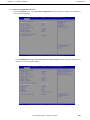
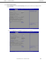
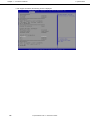
System BIOS .............................................................................................................................................. 52
1.1 Starting SETUP................................................................................................................................ 52
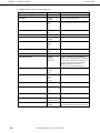
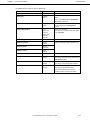
1.2 Parameter Descriptions ................................................................................................................... 52
1.2.1
Main ................................................................................................................................... 52
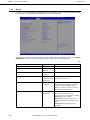
1.2.2
Advanced ........................................................................................................................... 54
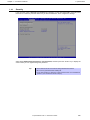
1.2.3
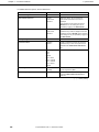
Security .............................................................................................................................. 67
1.2.4
Server ................................................................................................................................ 72
1.2.5
Boot ................................................................................................................................... 76
1.2.6
Save & Exit ........................................................................................................................ 78
2.
Flash FDD ................................................................................................................................................... 79
2.1 Precautions ...................................................................................................................................... 79
2.1.1
Compensation for recorded data ....................................................................................... 79
2.1.2
Handling the Flash FDD .................................................................................................... 79
2.1.3
Precautions when using EXPRESSBUILDER ................................................................... 80
3.
Power Control Feature ................................................................................................................................ 81
3.1 Supported OS .................................................................................................................................. 81
3.2 Notes on Using Windows Server 2008 ............................................................................................ 81
4.
RAID System Configuration ........................................................................................................................ 82
4.1 Running the LSI Software RAID Configuration Utility ...................................................................... 82
4.1.1
Exiting the LSI Software RAID Configuration Utility ........................................................... 83
4.2 Menu Tree........................................................................................................................................ 84
4.3 LSI Software RAID Configuration Utility Operating Procedure......................................................... 86
4.3.1
Creating and adding a configuration .................................................................................. 86
4.3.2
Executing rebuilding manually ........................................................................................... 91
4.3.3
Setting a hot spare Hard Disk Drive ................................................................................... 92
4.3.4
Executing a Consistency Check ........................................................................................ 94
4.3.5
Other functions .................................................................................................................. 95
4.4 LSI Software RAID Configuration Utility and Universal RAID Utility................................................. 96
4.5 WebBIOS and Universal RAID Utility............................................................................................... 98
4.6 SuperBuild Utility and Universal RAID Utility ................................................................................. 100
Express5800/GT110e-S
Maintenance Guide
Contents
5.
Details of EXPRESSBUILDER .................................................................................................................. 101
5.1 Storage Media................................................................................................................................ 101
5.2 Menu .............................................................................................................................................. 102
5.3 Utilities Provided by EXPRESSBUILDER ...................................................................................... 105
5.4 Configure EXPRESSBUILDER Settings ........................................................................................ 106
6.
EXPRESSSCOPE Engine 3 ..................................................................................................................... 107
7.
NEC ESMPRO .......................................................................................................................................... 108
7.1 NEC ESMPRO Agent (for Windows) ............................................................................................. 108
7.2 NEC ESMPRO Manager................................................................................................................ 109
7.3 NEC ESMPRO Agent Extension .................................................................................................... 110
7.4 BMC Configuration ........................................................................................................................ 110
7.5 NEC ExpressUpdate Agent............................................................................................................ 110
8.
NEC Product Info Collection Utility............................................................................................................ 111
8.1 Usage ............................................................................................................................................ 111
9.
Universal RAID Utility ................................................................................................................................ 112
9.1 Easy Configuration Function .......................................................................................................... 112
9.2 Creating Logical Drive of RAID 6 ................................................................................................... 112
Chapter 3 Appendix ........................................................................................................................................... 113
1.
POST Error Message ................................................................................................................................ 114
2.
List of Windows Event Logs ...................................................................................................................... 124
3.
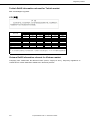
Accessing Data for Electric Power, Temperature, and Processor Utilization ............................................. 132
3.1 Windows ........................................................................................................................................ 132
3.1.1
Power consumption ......................................................................................................... 132
3.1.2
Intake air temperature ...................................................................................................... 133
3.1.3
Processor utilization......................................................................................................... 136
3.2 Linux .............................................................................................................................................. 137
3.2.1
Power consumption ......................................................................................................... 137
3.2.2
Intake air temperature ...................................................................................................... 138
3.2.3
Processor utilization......................................................................................................... 138
Express5800/GT110e-S
Maintenance Guide
5
Notations Used in This Document
Notations Used in This Document
Notations used in the text
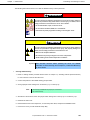
In addition to safety-related symbols urging caution, 3 other types of notations are used in this document.
These notations have the following meanings.
Important
Indicates critical items that must be followed when handling the hardware or operating
software. If the procedures described are not followed, hardware failure, data loss, and
other serious malfunctions could occur.
Note
Indicates items that must be confirmed when handling the hardware or operating software.
Tips
Indicates information that is helpful to keep in mind when using this server.
Optical disk drives
This server is equipped with one of the following drives, depending on the order at the time of purchase. These
drives are referred to as optical disk drives in this document.
• DVD-ROM drive
• DVD Super MULTI drive
Hard Disk Drives
Unless otherwise stated, Hard Disk Drives (HDD) described in this document refer to the following.
• Hard disk drives (HDD)
• Solid state drive (SSD)
Removable media
Unless otherwise stated, removable media described in this document refer to the following.
• USB memory
• Flash FDD
6
Express5800/GT110e-S
Maintenance Guide
Notations Used in This Document
Abbreviations of Operating Systems (Windows)
Windows Operating Systems are referred to as follows.
Refer to Chapter 1 (1.2 Supported Windows OS) in Installation Guide (Windows) for detailed information.
Notations in this document
Official names of Windows
Windows Server 2008 R2 Standard
Windows Server 2008 R2
Windows Server 2008 R2 Enterprise
Windows Server 2008 R2 Foundation
Windows Server 2008 Standard
Windows Server 2008
*1
Windows Server 2008 Enterprise
Windows Server 2003 R2 Standard x64 Edition
Windows Server 2003 R2 x64 Edition
Windows Server 2003 R2 Enterprise x64 Edition
Windows Server 2003 R2 Standard
Windows Server 2003 R2
*2
Windows Server 2003 R2 Enterprise
Windows Server 2003 Standard
Windows Server 2003
*2
Windows Server 2003 Enterprise
Windows 7 Professional 64-bit(x64) Edition
Windows 7
Windows 7 Professional 32-bit(x86) Edition
Windows Vista Business 64-bit(x64) Edition
Windows Vista
Windows Vista Business 32-bit(x86) Edition
Windows XP Professional x64 Edition
Windows XP
Windows XP Professional
Windows PE
*3
Windows Preinstallation Environment
*1: Includes 64-bit and 32-bit Editions unless otherwise stated.
The following appears on EXPRESSBUILDER.
•
•
Windows Server 2008 64-bit Edition:
Windows Server 2008 32-bit Edition:
Windows Server 2008 x64
Windows Server 2008 x86
*2: Unless otherwise stated, Windows Server 2003 R2 and Windows Server 2003 are collectively referred to as
Windows Server 2003.
*3: Used as an installation platform only.
Express5800/GT110e-S
Maintenance Guide
7
Trademarks
Trademarks
EXPRESSSCOPE is a registered trademark of NEC Corporation.
Microsoft, Windows, Windows Server, Windows Vista, and MS-DOS are registered trademarks or trademarks of Microsoft
Corporation in the United States and other countries. Intel, Pentium, and Xeon are registered trademarks of Intel Corporation of the
United States. AT is a registered trademark of International Business Machines Corporation of the United States and other countries.
Adaptec, its logo, and SCSI Select are registered trademarks or trademarks of Adaptec, Inc. of the United States. LSI and the LSI
logo design are trademarks or registered trademarks of LSI Corporation. Adobe, the Adobe logo, and Acrobat are trademarks of
Adobe Systems Incorporated. DLT and DLTtape are trademarks of Quantum Corporation of the United States. PCI Express is a
trademark of Peripheral Component Interconnect Special Interest Group. Linux is a trademark or registered trademark of Linus
Torvalds in Japan and other countries. Red Hat® and Red Hat Enterprise Linux are trademarks or registered trademarks of Red Hat,
Inc. in the United States and other countries.
All other product, brand, or trade names used in this publication are the trademarks or registered trademarks of their respective
trademark owners.
8
Express5800/GT110e-S
Maintenance Guide
Regulatory Notices
Regulatory Notices
FCC Statement
This equipment has been tested and found to comply with the limits for a Class A digital device, pursuant
to Part 15 of the FCC Rules. These limits are designed to provide reasonable protection against harmful
interference when the equipment is operated in a commercial environment. This equipment generates,
uses, and can radiate radio frequency energy and, if not installed and used in accordance with the
instruction manual, may cause harmful interference to radio communications. Operation of this equipment
in a residential area is likely to cause harmful interference in which case the user will be required to
correct the interference at his own expense.
Industry Canada Class A Emission Compliance Statement
This Class A digital apparatus complies with Canadian ICES-003.
Avis de conformité à la réglementation d'Industrie Canada
Cet appareil numérique de la classe A est conforme à la norme NMB-003 du Canada.
CE / Australia and New Zealand Statement
This is a Class A product. In domestic environment this product may cause radio interference in which
case the user may be required to take adequate measures (EN55022).
BSMI Statement
Disposing of your used product
In the European Union
EU-wide legislation as implemented in each Member State requires that used electrical and
electronic products carrying the mark (left) must be disposed of separately from normal
household waste. This includes Information and Communication Technology (ICT) equipment
or electrical accessories, such as cables or DVDs.
When disposing of used products, you should comply with applicable legislation or
agreements you may have. The mark on the electrical and electronic products only applies to
the current European Union Member States.
Outside the European Union
If you wish to dispose of used electrical and electronic products outside the European Union,
please contact your local authority and ask for the correct method of disposal.
Express5800/GT110e-S
Maintenance Guide
9
Regulatory Notices
Turkish RoHS information relevant for Turkish market
EEE Yönetmeliğine Uygundur
CCC声明
部件名称
印刷线路板
铅
(Pb)
×
汞
(Hg)
○
有毒有害物质或元素
镉
六价铬
(Cd)
(Cr(Ⅵ))
○
○
多溴联苯
(PBB)
○
多溴二苯醚
(PBDE)
○
HDD、DVD等
×
○
○
○
○
○
机箱、支架
○
○
○
○
○
○
电源
×
○
○
○
○
○
键盘
×
○
○
○
○
○
其他(电缆、鼠标
×
○
○
○
○
○
等)
○:表示该有毒有害物质在该部件所有均质材料中的含量均在SJ/T11363-2006标准规定的限量要求以
下。
×:表示该有毒有害物质至少在该部件的某一均质材料中的含量超出SJ/T11363-2006标准规定的限量要
求。
Vietnam RoHS information relevant for Vietnam market
Complying with "CIRCULAR, No.30/2011/TT-BCT (Hanoi, August 10 2011), Temporary regulations on
content limit for certain hazardous substances in electrical products”
10
Express5800/GT110e-S
Maintenance Guide
Warnings and Additions to This Document
Warnings and Additions to This Document
1.
Unauthorized reproduction of the contents of this document, in part or in its entirety, is
prohibited.
2.
The contents of this document may change without prior notice.
3.
Do not make copies or alter the document content without permission from NEC Corporation.
4.
Every effort has been made to ensure the completeness of this document. However, if you
have any concerns, or discover errors or omissions, please contact your retailer.
5.
Regardless of these 4 items, NEC Corporation assumes no responsibility for effects resulting
from operations.
6.
The sample values used in this document are not the actual values.
Keep this document nearby so that you may refer to it as necessary.
Latest editions
This document was created based on the information available at the time of its creation. The screen images,
messages and procedures may differ from the actual screens, messages and procedures. Substitute as
appropriate when content has been modified.
The most recent version of User’s Guide, as well as other related documents, is also available for download
from the following website.
http://www.nec.com/
Express5800/GT110e-S
Maintenance Guide
11
1
NEC Express5800 Series
Express5800/GT110e-S
Maintenance
This chapter explains inspection and maintenance procedures, and what actions are to be taken in case of
trouble when operating this server.
1. Transfer, Movement, and Disposal
Describes how to transfer and move this server to a third party. Also describes how to dispose and store this
server.
2. Daily Maintenance
Describes what you must confirm for daily use, how to manage files, and how to clean the server.
3. User Support
Describes various services on this product. Services are offered from NEC and the maintenance service
companies authorized by NEC.
4. Collecting Failure Information
Describes how to collect information about the location where a failure occurred and its cause when the
server malfunctions. Refer to this chapter in case of a failure.
5. Troubleshooting
Describes how to identify the causes of problems and what actions are to be taken to address them. Refer to
this chapter when you suspect a failure.
6. Windows System Recovery
Describes Windows recovery setup. Refer to this chapter when the Windows is corrupt.
7. Resetting and Clearing the Server
Describes how to reset or clear the server. Refer to this chapter when the server is not working or when you
wish to restore the settings made in BIOS to the factory settings.
8. System Diagnostics
Describes system diagnostics of this server and checking connection status check.
9. Offline Tools
Describes tools for preventive maintenance of this product.
12
Express5800/GT110e-S
Maintenance Guide
Chapter 1
Maintenance
1.
1. Transfer, Movement, and Disposal
Transfer, Movement, and Disposal
1.1
Transfer to a Third Party
Observe the following precautions when you transfer (or sell) the server or software provided with the server
to a third party.
•
Server
When transferring (or selling) the server to a third party, be sure to provide this manual (including electronic
data) to the third party.
•
Data on the Hard Disk Drive
Be sure to erase Hard Disk Drive data to prevent the leakage of sensitive data (such as customer
information or company management information) to any third parties. It is the user’s responsibility to erase
this data.
Important
NEC assumes no liability for data leakage should the product be transferred
to a third party without erasing the data.
Data seems to be erased when you empty "Recycle Bin" of Windows or execute the "format" command of
the operating system. However, the actual data remains on the Hard Disk Drive. Data not erased completely
might be restored by special software and used for unexpected purposes.
•
Bundled software
Observe the following precautions when transferring (selling) the provided software to a third party.
−
Transfer them with the server.
−
All provided media and documents must be transferred and no backup copies must be retained.
−
Transfer requirements listed in "Software License Agreement" that comes with each software application
must be satisfied.
−
Software on client PC must be uninstalled before transferring.
Express5800/GT110e-S
Maintenance Guide
13
Chapter 1
Maintenance
1.2
1. Transfer, Movement, and Disposal
Disposal of the Server and Consumables
•
Dispose of the server, Hard Disk Drives, DVD/CD-ROMs, option board, and battery according to laws and
regulations of the central and/or local government. Also dispose of the power cord attached to this product
together with the server to prevent diversion to other products.
Note
• For disposal (or replacement) of the battery on the mother board of the server,
consult with your sales representative.
• It is the user’s responsibility to completely erase all data stored on storage
devices such as Hard Disk Drives, backup data cartridges, or any other media
(such as CD-R/CD-RW) so that the data cannot be restored by a third party.
•
1.3
Some components including fans, built-in batteries, and the optical disk drive work for a limited period of
time and require replacement. For stable operation of the server, NEC recommends you regularly replace
these components. Contact the store where you purchased the server or a maintenance service company
for information on replacement or the lifetime of components.
Regarding the Transportation of This Server
This server and/or some of the associated optional devices uses lithium metal batteries or lithium ion batteries.
Regulations for air/ocean transportation apply when transporting lithium batteries. Conform to
theregulations if you want to transport this server or optional devices by air or ship.
1.4
Moving and Storage
Follow the steps below when you move or store this server.
WARNING
Be sure to observe the following precautions to use the server safety. Failure to
observe the precautions may cause death or serious injury. For details, refer to
Safety precautions in Precautions for Use in "User’s Guide".
• Do not disassemble, repair, or alter the server.
• Do not remove the lithium, NiMH, or Li-ion batteries.
• Disconnect the power plug before installing or removing the server.
14
Express5800/GT110e-S
Maintenance Guide
Chapter 1
Maintenance
1. Transfer, Movement, and Disposal
CAUTION
Be sure to observe the following precautions to use the server safely. Failure to
observe the precautions may cause burns, injury, and property damage. For
details, refer to Safety precautions in Precautions for Use in "User’s Guide".
• Do not lift the server by its front bezel or air duct.
• Make sure to complete installation.
• Do not get your fingers caught.
• Be careful of handling internal components that may be at high temperatures.
Note
• If the server has a built-in Hard Disk Drive, move the server while being careful
not to damage the drive.
• When storing the server, monitor the environmental conditions of the storage
area (temperature: −10°C to 55°C, humidity: 20% to 80%). (No dew
condensation is permitted)
Tips
Make backup copies of important data stored in the Hard Disk Drive.
1. Remove the media from the optical disk drive
2. Power off the server (POWER LED goes off)
3. Unplug the power cord of the server from the power outlet.
4. Disconnect all the cables from the server
5. Pack the server securely to protect from damage, shock, and vibration.
Important
If this server and internal optional devices are suddenly moved from a cold
place to a warm place, condensation will occur and cause malfunctions and
failures when these are used in such state. Wait for a sufficient period of time
before using the server and other components in the operating environment.
Note
• Check and adjust the system clock before operating after relocating or storing
the server.
• If the system clock time is significantly delayed or advanced over time in spite of
adjustment, contact your sales representative.
Express5800/GT110e-S
Maintenance Guide
15
Chapter 1
Maintenance
2.
2. Daily Maintenance
Daily Maintenance
To use this server under top conditions at all times, periodically check and perform maintenance as follows. If
abnormalities are found, ask your sales representative, avoiding impossible operation.
2.1
Checking and Applying Updates
Express5800 Series posts update information for BIOS, FW (firmware), driver, and others of the server and
peripheral devices on our website. We recommend that the latest update always be applied for stable system.
NEC corporate site: http://www.nec.com/
[Support & Downloads]
NEC also provides the tool ExpressUpdate that supports the detection, download, and application of the
updates that must be applied to BIOS and FW (firmware) of the server.
ExpressUpdate is contained in EXPRESSBUILDER provided with the server.
Tips
• Download and apply the latest update yourself.
• NEC recommends that you back up data for a rainy day before applying the
latest update.
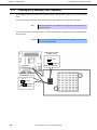
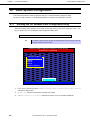
2.2
Checking Alerts
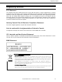
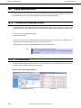
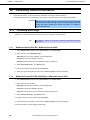
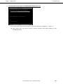
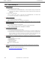
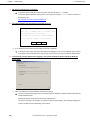
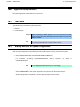
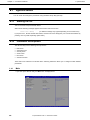
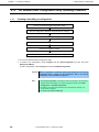
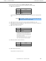
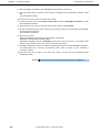
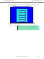
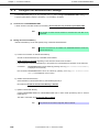
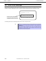
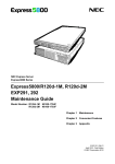
Use NEC ESMPRO Manager (for Windows) to constantly verify that no abnormalities are discovered on the
monitored server and that no alerts have been issued.
Example image of NEC ESMPRO Manager
NEC ESMPRO Manager
16
Express5800/GT110e-S
AlertViewer
Maintenance Guide
Chapter 1
2.3
Maintenance
2. Daily Maintenance
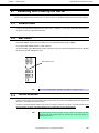
Status Indicator LEDs
After powering on the server or before shutting down the system and powering off the server, check the status
indicator LEDs on the front of the server. For the functions and descriptions of LEDs, refer to Chapter 1 (5.
Names and Functions of Parts) in "User’s Guide". If the indicator shows the server abnormality, contact your
salses representative.
2.4
Backup
We recommend that you periodically back up the data on HDD.
If RAID System has been setup on your system, back up RAID Configuration Data. We also recommend that
you back up it after a rebuilt required due to HDD failure. For information on RAID Configuration Data backup,
refer to the utility offered by EXPRESSBUILDER in Chapter 2 (5. Details of EXPRESSBUILDER).
2.5
Cleaning
Regularly clean the server to keep it in good condition.
WARNING
Be sure to observe the following precautions to use the server safety. Failure to
observe the precautions may cause death or serious injury. For details, refer to
Safety precautions in Precautions for Use in "User’s Guide".
• Do not disassemble, repair, or alter the server.
• Disconnect the power plug before cleaning the server.
Express5800/GT110e-S
Maintenance Guide
17
Chapter 1
2.5.1
Maintenance
2. Daily Maintenance
Cleaning the server
For daily cleaning, wipe the external surfaces of the server with a dry soft cloth. Follow the procedure below
if stains remain on the surfaces.
Important
• Do not use volatile solvents such as thinner and benzene to clean the
server. Those solvents could damage or tarnish the material.
• The power outlet, cables, connectors on the server, and the inside of the
server must be kept dry.
1. Confirm that the power is OFF (POWER LED is OFF)
2. Unplug the power cord of the server from a power outlet.
3. Wipe off dust from the power cord plug with a dry cloth.
4. Soak a soft cloth in neutral detergent that is diluted with cold or lukewarm water, and squeeze it firmly.
5. Rub off stains on the server with the cloth prepared in Step 4.
6. Soak a soft cloth in water, squeeze it firmly, and wipe the server with it once again.
7. Wipe the server with a dry cloth.
2.5.2
Cleaning the tape drive
A dirty tape drive head causes unsuccessful file backup and damages the tape cartridge. Periodically clean
the tape drive with the designated cleaning tape.
For the cleaning interval and method, the estimated usable period and lifetime of the tape cartridge, refer to
the manual attached to the tape drive.
2.5.3
Cleaning the keyboard and mouse
Wipe the surface of the keyboard with a dry cloth after confirming that the whole system, including the server
and the peripherals, are shut down and the POWER LED is off.
An optical mouse does not work properly if the lens area is not clean. Wipe the sensor with a dry cloth to
remove any dirt or dust.
18
Express5800/GT110e-S
Maintenance Guide
Chapter 1
Maintenance
3.
3. User Support
User Support
Before getting after-sales service, check the contents of the warranty and service.
3.1
Maintenance Services
Service representatives from NEC subsidiary companies or companies authorized by NEC provide
maintenance services. For the services, contact your sales representative.
3.2
Before Asking for Repair
If you think that a failure occurred, follow the steps below:
1. Check if the power cord and cables to other products are properly connected.
2. Refer to Chapter 1 (5. Troubleshooting). If you find a symptom similar to your problem, take the action as
instructed.
3. Confirm that the required software has been properly installed.
4. Scan for viruses using a commercial Antivirus Software.
If the problem persists after taking the measures above, contact your sales representative. Take notes on LED
indications and the display on the screen at the failure, which will be useful information for the repair.
For repair within the warranty period, be sure to apply with your warranty.
Express5800/GT110e-S
Maintenance Guide
19
Chapter 1
Maintenance
4.
4. Collecting Failure Information
Collecting Failure Information
If the server is broken, you can collect failure information by using the following method.
The failure information to be described is to be collected only at the request of your sales representative.
Important
When the system restarts after a failure has occurred, a message may appear
indicating virtual memory shortage. Ignore this message and proceed with
starting the system. Restarting the system may result in an inability to
properly dump the data.
4.1
Collecting Event Logs
Collection for various event logs that occurred on the server follows the steps below.
Tips
4.1.1
If a STOP error, system error, or stall occurs, restart the system and then follow the
steps below.
Windows Server 2008 R2 / Windows Server 2008
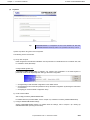
1. Select Administrative Tool and then Event Viewer from Control Panel.
2. Select the type of log in Windows Logs.
Application records events related to running applications.
Security records events related to security.
System records events that occur in Windows system components.
3. Select Save All Event As... from Action menu.
4. Enter the file name of the archived log in File name.
5. Select the type of the log file you want to save in Save as type, and then click [Save].
4.1.2
Windows Server 2003 R2 x64 Edition / Windows Server 2003
1. Select Administrative Tool and then Event Viewer from Control Panel.
2. Select the type of log to collect.
Application records events related to running applications.
Security records events related to security.
System records events that occur in Windows system components.
3. Select Save All Event As... from Action menu.
4. Enter the file name of the archived log in File name.
5. Select the type of the log file you want to save in Save as type, and then click [Save].
For more information, refer to Windows Online help.
20
Express5800/GT110e-S
Maintenance Guide
Chapter 1
4.2
Maintenance
4. Collecting Failure Information
Collecting Configuration Information
This section describes how to collect information on hardware configuration and internal specifications.
Tips
If a STOP error, system error, or stall occurs, restart the system and then follow the
procedure below.
1. Select Run from Start menu.
2. Enter msinfo32.exe in Open text box, and then click [OK].
3. System Information starts.
4. From Files menu, click Export.
5. Enter the file name to save in File Name, and then Click [Save].
4.3
Collecting User-Mode Process Dump (Dr. Watson Diagnostic
Information)
Dr. Watson collects diagnostic information related to application errors.
For details, refer to Chapter 1 (7.2 How to Create a User-Mode Process Dump File) in "Installation Guide
(Windows)".
4.4
Collecting Memory Dump
If an error occurs, the dump file should be saved to acquire necessary information. You can specify any
location for saving the diagnostic information. For details, refer to Chapter 1 (7.1 Specifying Memory Dump
Settings (Debug Information)) in "Installation Guide (Windows)".
Consult with your sales representative before dumping the memory. Dumping the memory while the server is
in operating normally may affect the system operation.
Important
A message indicating insufficient virtual memory may appear when
restarting the system due to an error. Ignore this message and proceed.
Restarting the system may result in an inability to properly dump the data.
Express5800/GT110e-S
Maintenance Guide
21
Chapter 1
Maintenance
5.
5. Troubleshooting
Troubleshooting
If this system does not operate as intended, check it according to the contents of the following checklist before
sending it for repair. If an item in the checklist corresponds with a problem you are experiencing, follow the
subsequent check and processing instructions.
If the system still does not operate normally, write down the messages displayed on the screen and then contact
the maintenance service company.
5.1
[?]
Upon Power On to the End of POST
When the power cable is connected, the POWER LED turns on.
→
The POWER LED lights amber during initialization of the server after connecting the power cord. The
POWER LED turns off when initialization finishes. This is a normal operation, not a malfunction.
[?]
When the power cable is connected, the POWER LED turns on.
→
Although the POWER LED turns on immediately after AC power is supplied, no error has occurred.
The POWER LED turns off when the POWER switch is turned ON/OFF.
[?]
Fail to power on the server
Is the server properly supplied with power?
→
Check if the power cord connects to the power outlet (or UPS) that meets the power specifications for
the server.
→
Use the power cord that comes with the server. Additionally, check the power cord for broken shield or
bent plugs.
→
Make sure the power breaker for the connected power outlet is on.
→
If the power cord is plugged to a UPS, make sure the UPS is powered and it outputs power. Refer to the
manual that comes with the UPS for details.
Power supply to the server may be linked with UPS using the BIOS Setup utility.
Did you press the POWER switch?
→
Press the POWER switch on the front of the server to turn on the power (the POWER LED ON).
→
When the power cord is connected, the management controller is initialized. The power cannot be
turned on during initialization, even if the POWER switch is pressed. The POWER LED lights amber
during initialization. Press the POWER switch after the POWER LED turns off.
Is Standby Power Save set to Enable in the BIOS setup?
→
When Standby Power Save is enabled, remote power on is not allowed, and you can power on the
server only by using the power switch on the server. If you change the AC Link setting while Standby
Power Save is enabled, you need to press the power switch twice to start up the server.
22
Express5800/GT110e-S
Maintenance Guide
Chapter 1
[?]
Maintenance
5. Troubleshooting
POST does not complete
Is memory installed correctly?
→
You must install at least 1 DIMM for the server to operate.
Is the memory size large?
→
The memory check may take longer than usual if the installed memory size is large. Wait for a while.
Did you perform any keyboard or mouse operation immediately after you started the server?
→
If you perform any keyboard or mouse operation immediately after start-up, POST may accidentally
detect a keyboard controller error and stops processing. In such a case, reboot the server. Do not
perform any keyboard or mouse operation until the BIOS start-up message appears after you reboot the
server.
Are memory and PCI devices supported for use with this server?
→
Operation of the server with unauthorized devices is not guaranteed.
Express5800/GT110e-S
Maintenance Guide
23
Chapter 1
Maintenance
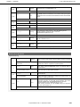
5.2
[?]
5. Troubleshooting
Upon Starting EXPRESSBUILDER
Unable to start EXPRESSBUILDER
Did you insert the EXPRESSBUILDER DVD and reboot while POST was being executed?
→
The server tries to read CD/DVD upon completion of POST. If EXPRESSBUILDER is not set at this
timing, an error message may appar or the OS starts up. Restart the server and retry.
Are BIOS settings correct?
→
The BIOS setup utility allows you to configure the boot order of the boot devices. Configure the boot
order so that the optical disk drive will be the first to start up.
(Check menu: Boot)
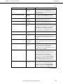
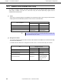
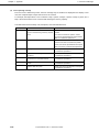
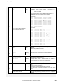
Is a message such as the following displayed?
→
Take an appropriate action according to the table below.
Message
Cause
This EXPRESSBUILDER version is not designed for this
computer.
Insert the correct version and click [OK].
Execute the NEC EXPRESSBUILDER
provided with the server.
EXPRESSBUILDER could not get the hardware parameters of this
motherboard.
This version is not designed for this computer or the
motherboard may be broken.
Contact your sales representative.
The file that EXPRESSBUILDER tried to operate was not found.
EXPRESSBUILDER cannot be read.
Media may be defective or the optical
disk drive may be faulty.
Contact the maintenance service
company.
The file that EXPRESSBUILDER tried to operate was not able
to open.
EXPRESSBUILDER can not get the parameters of the definition
file.
An undefined error occurred.
[?]
Contact your sales representative.
Unable to start EXPRESSBUILDER from the Internal Flash Memory
Did you press the <F3> key to start EXPRESSBUILDER from the Internal Flash Memory while POST was
being executed?
→
When the following message, "Press <F2> Setup, <F3> Internal Flash Memory, <F4> ROM Utility,
<F12> Network", appears on screen after starting up, press <F3> to start EXPRESSBUILDER from the
Internal Flash Memory.
Is there a message, "<F3> Internal Flash Memory", displayed on the POST screen?
→
If not, make sure that the Internal Flash Memory is connected correctly by referring Chapter 2 (5. Details
of EXPRESSBUILDER).
Did you purchase the Internal Flash Memory as BTO?
→
If not, copy EXPRESSBUILDER to the Internal Flash Memory first by referring to Chapter 2 (5. Details of
EXPRESSBUILDER).
24
Express5800/GT110e-S
Maintenance Guide
Chapter 1
[?]
Maintenance
5. Troubleshooting
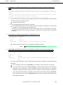
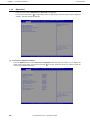
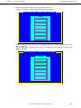
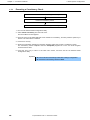
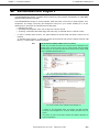
The following message appears and EXPRESSBUILDER failed to start.
Did you press <Enter> key consecutively twice or more when selecting "Os installation *** default ***" ?
→
Press <Enter> key on the above screen for selecting "Windows Setup [EMS Enabled]" to start
EXPRESSBUILDER.
Express5800/GT110e-S
Maintenance Guide
25
Chapter 1
Maintenance
5.3
[?]
5. Troubleshooting
Upon Installing OS
Unable to install OS
Did you configure the RAID Controller?
→
For the RAID System, use EXPRESSBUILDER or a RAID Configuration Utility (LSI Software RAID
Configuration Utility, WebBIOS, or SuperBuild Utility) to properly configure the RAID Controller before
installing OS.
Did you create a Logical Drive?
→
For the RAID System, create a Logical Drive using EXPRESSBUILDER, LSI Software RAID
Configuration Utility, WebBIOS, or SuperBuild Utility to install OS.
[?]
Unable to install Windows
Have you checked precautions for installation?
→
[?]
For Windows Server 2003, refer to "Installation Guide (Windows)".
While installing OS on Windows Server 2003 x64 Edition or Windows Server 2003, a driver list of the OEM
drivers is not displayed
Did you change the boot priority in the Flash FDD?
→
Start the BIOS setup utility, and change the boot priority in the Flash FDD as follows.
Boot - Floppy Drive BBS priorities - Boot Option #1 - Flash FDD
[?]
A product key was not requested
For Windows Server 2008 R2/Windows Server 2008
→
If you install using the backup DVD-ROM, entering the product key is not required. If installing using a
DVD-ROM other than the backup DVD-ROM, a screen for entering the product key is displayed twice,
during OS installation, and, before the MICROSOFT SOFTWARE LICENSE TERMS dialog box, which
displays after OS installation. Follow the on-screen instructions to enter the product key.
[?]
The following devices are indicated as faulty devices in a Windows Server 2008 R2 ServerCore installation
environment
•
•
•
•
•
→
[?]
SM Bus Controller
PCI Simple Communications Controller
Base System Device
System Interrupt Controller
Performance Controller
There is no operational problem.
Unable to access the partition which was previously created after reinstalling while several disks are
connected
→
For details, refer to the Microsoft website below:
http://support.microsoft.com/kb/2497048/ja (Japanese only)
26
Express5800/GT110e-S
Maintenance Guide
Chapter 1
[?]
Maintenance
5. Troubleshooting
When Windows Server 2008 R2 is installed while several disks are connected, the system partition and
the boot partition (100 MB) are sometimes created in another disk
→
For details, refer to the Microsoft website below:
http://support.microsoft.com/kb/2530901/ja (Japanese only)
[?]
When Starter Pack is executed on Windows Server 2008 R2, the below message is sometimes displayed
for a moment upon shutdown
1 program still needs to close:
(Waiting for) Task Host Window
→
No problems for system operation.
For details, refer to the Microsoft website below:
http://support.microsoft.com/kb/975777/en-us
[?]
Windows Server 2003 R2 DISC 2 was installed after the Windows Server 2003 Service Pack had been
applied
→
Reapply the Service Pack. If you applied the Service Pack even once after installing Windows Server
2003 R2 DISC 2, you need not reapply it.
* If the Service Pack application is unknown when you install Windows Server 2003 R2 DISC 2, NEC
recommends that the Service Pack be reapplied.
[?]
The message “PCI Express Correctable” is registered in the DMI event log when installing Windows.
→
[?]
This message may be registered when installing Windows. There is no operational problem.
The system was installed as Workgroup although it is set to join the domain
Is the LAN cable properly connected?
→
If the LAN cable is not connected, the system is installed in workgroup setting, not in domain join setting.
After the OS is started, join the domain.
[?]
The following functions are installed when Windows Server 2008 R2 or Windows Server 2008 was set up
using EXPRESSBUILDER and when IISis installed.
Windows Process Activation Service
−
Process Model
−
Configuration APIs
Remote Server Administration Tool
−
Role Administration Tools
−
Web Server (IIS) Tools
→
The features listed above are activated because they are required for the installation of IIS basic
features.
Express5800/GT110e-S
Maintenance Guide
27
Chapter 1
[?]
Maintenance
5. Troubleshooting
The Telnet Service is not installed
→
Adjust the computer name to 14 characters or less, and then install the Telnet Service according to the
following procedure:
How to install the Telnet Service
(1) Click Run on Start menu.
(2) Enter tlntsvr/service in the Open box, and then click [OK].
(3) Click Start menu, point to Control Panel, click Administrative Tools, and then click Services to
confirm whether the Telnet Service is registered.
* When the installation of Telnet Service is finished, there is no problem if the computer name is set to
15 characters or more.
[?]
Fails to execute "Create a parameter file for Windows OS"
→
®
"Create a parameter file for Windows OS" must be run using Microsoft HTML Application host. If it
®
does not start, associate the file type with Microsoft HTML Application host via the following process.
(1) Select Run in Windows Start menu.
(2) Enter %windir%\system32\mshta.exe/register.
28
Express5800/GT110e-S
Maintenance Guide
Chapter 1
Maintenance
5.4
[?]
5. Troubleshooting
When OS is Started
It takes too long to start the OS or the OS does not start up
Is the ROM on the PCI board or the network boot (PXE boot) enabled?
→
For a SCSI controller, if no Hard Disk Drive on which an OS is installed is connected, set the ROM for
that slot to Disabled. When you do not perform the network boot from the network interface card (NIC),
memory consumption and start-up time can be reduced by disabling ROM on NIC.
Menu to be checked: Advanced → PCI Configuration → submenu for each controller
If no Hard Disk Drive on which an OS is installed is connected, set the ROM for that slot to Disabled.
[?] Unable to start OS
Has the BIOS configuration of the RAID Controller changed?
→
Set the correct BIOS configuration with a RAID Configuration Utility (LSI Software RAID Configuration
Utility or WebBIOS).
Is the RAID Controller recognized by POST?
→
Turn on the power after the RAID Controller is recognized as being connected successfully.
→
If the RAID Controller is not recognized as being connected successfully, the RAID Controller may be
faulty. Contact the maintenance service company with which you signed up or the dealer where you
purchased the product.
Is RAID Controller inserted firmly straight into the PCI slot?
→
Install the RAID Controller properly.
Is the RAID Controller mounted on the PCI slot for which the mounting is restricted?
→
Check the mounting restrictions of the server and then mount the RAID Controller on the correct slot.
If the RAID Controller is not recognized as connected although the above action has been taken, the
RAID Controller may be faulty. Contact the maintenance service company with which you signed up or
the dealer where you purchased the product.
Are Hard Disk Drives properly installed?
→
Install the RAID Controller properly.
Is SAS cable connected to Hard Disk Drive correctly? (check connections with Hard Disk Drives)
→
Connect the SAS cable properly.
If the SAS cable is not recognized as connected although the above action has been taken, the Hard
Disk Drive may be faulty. Contact the maintenance company with which you signed up or the dealer
where you purchased the product.
Is the EXPRESSBUILDER DVD inserted?
→
Eject the EXPRESSBUILDER DVD and reboot.
Is the OS corrupt?
→
Refer to Chapter 1 (6. Windows System Recovery) to recover the OS.
Express5800/GT110e-S
Maintenance Guide
29
Chapter 1
[?]
Maintenance
5. Troubleshooting
OS does not start with the /3GB switch
→
In Windows Server 2003 x86, System may fail to start the OS with the /3GB switch.
In this case, please adjust the capacity of the user mode area using the /userva switch in reference to
the following URL.
http://support.microsoft.com/kb/316739/en-us
[?]
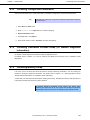
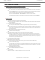
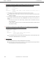
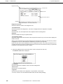
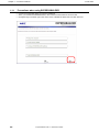
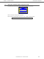
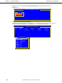
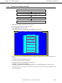
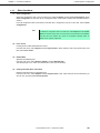
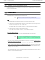
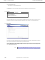
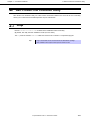
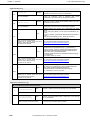
The system displays the message below and fails to log on:
Windows Product Activation
This copy of Windows must be activated with
Microsoft before you can continue.
You cannot log on until you activate Windows.
To shut down the computer, click [Cancel].
Yes (Y)
No (N)
Cancel
Is the Windows product license authentication procedure completed?
→
In Windows Server 2003, the above message will be displayed if you use the operating system without
executing the license authentication. Select [Yes], and execute the procedure for license authentication.
[?]
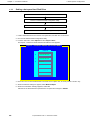
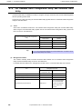
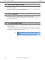
The following message appears when logging in the system on Windows Server 2008 R2 or Windows
Server 2008:
Have you finished license authentication for Windows product?
→
The above message will appear if you use Windows Server 2008 R2 or Windows Server 2008 with the
unauthenticated license.
Select [Get Genuine now] and proceed license authentication.
The above message is an example of request for license authentication. The message displayed on
screen may differ from this depending on the license.
30
Express5800/GT110e-S
Maintenance Guide
Chapter 1
Maintenance
5.5
5. Troubleshooting
When STOP Error Occurs
[?] Cannot turn the power OFF at the blue screen (STOP error screen)
→
If you want to turn off the power at the blue screen, execute forced shutdown (continue to press the
POWER switch for 4 seconds). If you press the switch briefly instead of holding it, the server will not
power off.
Express5800/GT110e-S
Maintenance Guide
31
Chapter 1
Maintenance
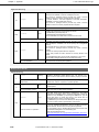
5.6
[?]
5. Troubleshooting
When Operating a RAID System
Unable to rebuild Hard Disk Drive
Is the capacity of the Hard Disk Drive to be rebuilt enough?
→
Use a Hard Disk Drive with the same capacity as that of the faulty Hard Disk Drive.
Is the Logical Drive RAID0?
→
RAID0 cannot be rebuilt because it has no redundancy. Replace the failed Hard Disk Drive, recreate the
configuration information, initialize it, and recover the drive using backup data.
[?]
Fails to automatically rebuild the Hard Disk Drive
Did you secure sufficient time for replacing the Hard Disk Drive?
→
To make auto-rebuild work, secure at least 90 seconds from when a Hard Disk Drive is removed to
when the drive is installed.
Are settings correct?
→
Use the LSI Software RAID Configuration Utility to check the Auto Rebuild settings.
TOPMENU → Objects → Adapter → Auto Rebuild
* The Auto Rebuild settings are not available in WebBIOS.
[?]
The Hard Disk Drive failed
→
Contact the maintenance service company with which you signed up or the dealer where you purchased
the product.
[?]
A part of Physical Device information of Universal RAID Utility is not be displayed correctly
→
If LSI Embedded MegaRAID is used, a part of Physical Device information of Universal RAID Utility may
not be displayed correctly.
[?]
Unable to perform Consistency Check
Is the Logical Drive Critical or Degraded?
→
Replace the failed Hard Disk Drive with new one, and then perform Rebuild.
Is RAID0 configured for the Logical Drive?
RAID0 has no data redundancy, and therefore, Check Consistency is disabled in the RAID0 configuration.
[?]
Cannot set Write-Back for Cache Mode
→
The current cache of RAID Controller is displayed on Virtual Disks – Properties – Policies – Write. If
an extra battery is faulty, is not connected, or insufficiently charged, the Cache Mode is changed to
WThru (Write Through) even if you specify WBack (Write Back).
For the description of the Cache Mode, refer to Chapter 2 (4. RAID System Configuration).
32
Express5800/GT110e-S
Maintenance Guide
Chapter 1
[?]
Maintenance
5. Troubleshooting
The N8103-141 or N8103-153 extra battery is not recognized or the following message is displayed in
POST
The battery hardware is missing or malfunctioning, or the battery is unplugged, or the battery
could be fully discharged. If you continue to boot the system, the battery-backed cache will not
function.
If battery is connected and has been allowed to charge for 30 minutes and this message continues
to appear, then contact technical support for assistance.
Press ‘D’ to disable this warning (if your controller does not have a battery.
Are the cable between the battery pack and battery board and the control cable between the battery board
and battery connector connected correctly?
Connect the cables correctly.
→
Is this message displayed after the battery is connected?
If the battery charging status is low, the battery may not be recognized. If the battery is not recognized
→
although 24 hours has passed, restart the system once.
If the battery is not recognized although the above action has been taken, the extra battery may be faulty.
Contact the maintenance service company with which you signed up or the dealer where you purchased
the product.
[?]
Event ID129: The following message appears on Windows Event Log
Event source : megasas2
Event ID
: 129
Type
: Warning
Description
: Reset to device, \Device\RaidPortX, was issued.
→
Retry by OS has succeeded. It is not the problem in operating the system.
Note
[?]
A different number replaces X depending on the system.
Event ID505: If the N8103-141 or N8103-153 extra battery is mounted, the following message may be
registered in the RAID log of Universal RAID Utility and OS logs (Windows event log, Linux syslog)
Event source : raidsrv
Event ID
: 505
Type
: Warning
Description
: <RU0505> [CTRL: Number of RAID Controller] Temperature of battery is
high.
If the above event is registered, check the Cache Mode (current value) of the RAID Controller with Universal
RAID Utility.
→
If the Cache Mode (current value) is Write Back, use the battery as is because there is no problem.
→
If the Cache Mode (current value) is Write Through, the battery refresh operation causes the battery
temperature to rise temporarily. This event temporarily stops the refresh operation, so the battery
temperature drops and the refresh operation resumes. However, it may take time till the temperature
drops. After the refresh operation is completed, the Cache Mode (current value) changes to Write Back.
If the Cache Mode does not change to Write Back although 24 hours have elapsed, the battery may be
faulty. Replace the battery.
Express5800/GT110e-S
Maintenance Guide
33
Chapter 1
[?]
Maintenance
5. Troubleshooting
Event ID508: If the N8103-141 or N8103-153 extra battery is mounted, the following message is registered
in the RAID log of Universal RAID Utility and OS logs (Windows event log, Linux syslog)
Event source : raidsrv
Event ID
: 508 (800001FC)
Type
: Warning
Description
: <RU0508> [CTRL: Number of RAID Controller] The battery status is
unstable.
Did the battery become unstable immediately after the extra battery had been mounted?
→
Immediately after the extra battery is mounted, this event may be registered till the battery refresh
operation is completed.
If this message is registered, wait for about 15 minutes and check the Cache Mode (current value) of the
RAID Controller. If the Cache Mode (current value) is Write Back, use the battery as is because there is no
problem.
→
If the current cache mode is set to “Write Through”, the battery needs to be refreshed. Contact your
service representative.
If “Write Through” is retained for 9 hours or more after starting refresh operation, the battery may be
faulty. Replace the battery.
[?]
Event ID510: The following event is logged in RAID log of Universal RAID Utility and OS log (Windows
event log or Linux syslog) when additionally battery is installed.
Event source : raidsrv
Event ID
: 510
Type
: Info
Description
: <RU0510> [CTRL: Number of RAID Controller]
Battery Refresh required.
→
Use Universal RAID Utility to perform battery refresh manually. Refer to Universal RAID Utility User's
Guide stored in EXPRESSBUILDER for more information.
[?]
DISK LED flashes
DISK LED flashes frequently even while the Hard Disk Drive is not accessed.
→
When Patrol Read is running, the DISK LED flashes even if the Hard Disk Drive is not being accessed. If
SATA Hard Disk Drive is used, the DISK LED may stay on.
34
Express5800/GT110e-S
Maintenance Guide
Chapter 1
Maintenance
5.7
[?]
5. Troubleshooting
When Using Internal Devices and Other Hardware
Fail to access the internal or external devices (or such devices fail to operate)
Are cables properly connected?
→
Make sure that the interface cables and power cord are properly connected. Also make sure that the
cables are connected in the correct order.
Is the power-on order correct?
→
When the server has any external devices connected, power on the external devices first, then the
server.
Did you install drivers for connected optional devices?
→
Some optional devices require specific device drivers. Refer to the manual that comes with the device to
install its driver.
Is option board setting correct?
→
Usually, no PCI device settings need to be changed. However, depending on the board to be set,
special setting may be required. Refer to the manual that comes with the board for details to make
correct settings.
→
Some devices connected to the serial or parallel port, or USB port may require I/O port address or
operation mode settings. Refer to the manual that comes with the device to make correct settings.
[?]
The keyboard or mouse does not work
Is the cable properly connected?
→
Make sure that the cable is connected to the connector on the front or rear of the server.
Is BIOS configuration correct?
→
You can use the BIOS setup utility to change the keyboard feature. Check the BIOS configuration with
this utility.
Are the server drivers installed?
→ Refer to the manual that comes with your OS to check that the keyboard and mouse drivers are installed.
(These drivers are installed along with the OS.) Some OS’s allow you to change the keyboard and
mouse settings. Refer to the manual to check that the keyboard and mouse settings are correct.
[?]
Unable to access the Hard Disk Drive
Is the Hard Disk Drive supported by the server?
→
Operation of any device that is not authorized by NEC is not guaranteed.
Is the Hard Disk Drive properly installed?
→
Check the Hard Disk Drive installation status and the cable connections. Use the screws provided with
the Hard Disk Drive to mount the Hard Disk Drive.
[?]
The Hard Disk Drive access LED lights up
→
The Hard Disk Drive access LED lights up when the Hard Disk Drive is accessed. This green light does
not indicate the disk failure.
Express5800/GT110e-S
Maintenance Guide
35
Chapter 1
Maintenance
5.8
[?]
5. Troubleshooting
When OS is in Operation
Windows operation is unstable
Have you installed the Starter Pack?
→
If the network driver is installed after OS is installed, Windows operation may become unstable.
Install the Starter Pack by referring to the description about how to install the Starter Pack for each OS
in "Installation Guide (Windows)".
[?]
After the system is restored from the backup tool, Windows is misbehaving
→
[?]
Use EXPRESSBUILDER to apply Starter Pack.
The system time lags
→
In Windows Server 2008, If you do not use the server that adjusts time such as NTP (Network Time
Protocol) Server, the system time may differ from actual time.
In this case, use NTP server or disable Windows Time Service.
[?]
Fails to be recognized on network
Is the cable connected properly?
→
Securely connect the proper cable to the network port on the rear of the server. Additionally, make sure
that the cable conforms to the network interface standards.
Are BIOS settings correct?
→
You can disable the internal network controller using the BIOS setup utility. Check the settings with
BIOS setup utility.
Have you completed protocol and services settings?
→
Verity that the network driver for the server network controller has been installed. Also verify that
protocol such as TCP/IP or various services have been properly specified.
Are transfer rate settings correct?
→
[?]
Verify that the transfer rate and duplex mode are the same as those of the connecting hubs.
There are RX dropped packets (ifInDiscards) when the system is in operation on Linux and Windows
→
Although there may be RX dropped packets when the LAN is received multicast frames, there is no
operational problem.
36
Express5800/GT110e-S
Maintenance Guide
Chapter 1
Maintenance
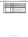
5.9
[?]
5. Troubleshooting
When EXPRESSBUILDER is Started on Windows
Cannot read online documents
Do you have Adobe Reader installed correctly in your system?
→
Some documents are supplied in PDF format. To read PDF files, Adobe Reader needs to be installed in
your computer.
Is your browser Internet Explorer?
→
Internet Explorer sometimes displays the Information bar to enforce security. If this happens, click the
Information bar to display the documents.
[?]
The menu does not appear
Is the operating system Windows XP or later, or Windows Server 2003 or later?
→
Operate this program with Windows XP or later, or Windows Server 2003 or later.
→
Windows Server 2008 Server Core is not supported.
Is the shift key pressed?
→
Setting the DVD/CD with the shift key pressed down cancels the Autorun feature.
Is the OS in the proper state?
→
The menu may not appear depending on the system registry setting or the timing to set the DVD/CD. In
such a case, select My Computer from Explorer and double-click the icon of the set DVD drive.
[?]
The menu items started by Autorun are unavailable
Is your system environment correct?
→
Some software requires administrator authority or needs to be operated on the server. Run on the
appropriate environment.
→
Confirm the settings of [Regional and Language Options]. Set the language settings of each tab to
English (US).
5.10
[?]
For Bundled Software
The installer was displayed by a wrong language or resulted in an error.
Is your system environment correct?
→
Confirm the settings of [Regional and Language Options]. Set the language settings of each tab to
English (US).
[?]
NEC ESMPRO Agent (for Windows)
→
For details of NEC ESMPRO Agent (for Windows), refer to "NEC ESMPRO Agent Installation Guide
(Windows)" in EXPRESSBUILDER or its help.
[?]
NEC ESMPRO Manager
→
For details of NEC ESMPRO Manager, refer to "NEC ESMPRO Manager Installation Guide" in
EXPRESSBUILDER or its help.
Express5800/GT110e-S
Maintenance Guide
37
Chapter 1
Maintenance
5.11
[?]
5. Troubleshooting
For Optical Disk Drives
Unable to access or play DVD/CD-ROMs
Is the DVD/CD-ROM properly set in the optical disk drive tray?
→
There is a holder in the tray to secure the disk. Make sure that the disk is securely placed in the holder.
Is the DVD/CD-ROM supported by the server?
→
For a disk such as a DVD/CD with copy guard which does not conform to the DVD/CD standard, the
playback of such a DVD/CD with the optical disk drive is not guaranteed.
→
The DVD/CD-ROM for Macintosh is not supported.
Is the data side of the DVD/CD-ROM dirty or damaged?
→
Remove the DVD/CD-ROM from the optical disk drive, make sure that it is neither dirty nor damaged,
set the DVD/CD-ROM again, and click [OK].
[?]
Unable to eject a disk using the eject button
→
Eject the disk in the following procedure.
1.
Press the POWER switch to turn off the server (POWER LED is off).
2.
Use a 100 mm long metal pin that
is 1.2 mm in diameter (or uncoil a
thick paper clip) and insert it into
the forced eject hole at the front of
Forced eject hole
the tray. The location of the force
eject hole may vary, depending on
the drive.
Important
• Do not use anything that easily breaks such as toothpicks or plastic.
• If you still cannot eject the disk, contact the maintenance service company.
38
3.
Pull the tray out with your hands.
4.
Remove the disk.
5.
Push the tray back to its original position.
Express5800/GT110e-S
Maintenance Guide
Chapter 1
Maintenance
5.12
[?]
5. Troubleshooting
When Power off
The power is not turned off
Is the suppression feature of the power switch enabled?
→
Restart the system once and start the BIOS setup utility.
The menu to be confirmed: Server → Power Switch Inhibit
Express5800/GT110e-S
Maintenance Guide
39
Chapter 1
Maintenance
6.
6. Windows System Recovery
Windows System Recovery
Recover the Windows system by following the instructions below if the files necessary to operate Windows are
corrupt.
Note
• After recovering the system, be sure to install each driver and Starter Pack,
referring to the descriptions about how to install Starter Pack and device driver
in "Installation Guide (Windows)".
• If Hard Disk Drive cannot be recognized, you cannot recover the Windows
system.
• Depending on the server configuration, you may be required to create a copy of
OEM drivers on a removable media.
6.1
Recovery of Windows Server 2008 R2 and Windows Server 2008
If Windows does not start for some reason, you can recover Windows using the system recovery option. Be
sure to perform this operation under the supervision of a user or administrator who has a thorough knowledge
of this option. For details, refer to Windows Help.
When OEM drivers are required, copy the files under the following designated folder in EXPRESSBUILDER to
a removable media.
6.2
• Windows Server 2008 R2:
\024\win\winnt\oemfd\ws2008r2
• Windows Server 2008 64-bit Edition:
\024\win\winnt\oemfd\ws2008x64
• Windows Server 2008 32-bit Edition:
\024\win\winnt\oemfd\ws2008
Recovery of Windows Server 2003 R2 x64 Edition and Windows Server 2003
If Windows does not start for some reason, you can recover Windows using the recovery console. Be sure to
perform this operation under the supervision of a user or administrator who has a thorough knowledge of this
method. For details, refer to Windows Help.
When OEM drivers are required, copy the files under the following designated folder in EXPRESSBUILDER to
a Flash FDD.
40
• Windows Server 2003 R2 x64 Edition:
\024\win\winnt\oemfd\w2k3amd
• Windows Server 2003 R2, Windows Server 2003:
\024\win\winnt\oemfd\dotnet
Express5800/GT110e-S
Maintenance Guide
Chapter 1
Maintenance
7.
7. Resetting and Clearing the Server
Resetting and Clearing the Server
Refer to this chapter when the server does not work or when you set BIOS settings back to the factory settings.
7.1
Software Reset
If the server halts before starting the OS, press <Ctrl> + <Delete> + <Alt> keys. This clears all the data in
progress in memory, and restarts the server.
7.2
BMC RESET
Press BMC RESET Switch only if a problem occurs in EXPRESSSCOPE Engine 3 (BMC).
Do not press BMC RESET Switch in usual operation.
To reset the BMC, press BMC RESET Switch at least five seconds. Remote management feature is disabled
for about 40 seconds after BMC is reset.
BMC RESET switch
Tips
7.3
Do not use the BMC RESET (M RESET) when BMC is operating normally.
Forced Shutdown
Use this function when an OS command does not shut down the server, the POWER switch does not turn off
the server, or software reset does not work.
Continue to hold the POWER switch of the server for at least 4 seconds. The power is forcibly turned off (To
turn the power on again, wait approximately 10 seconds after turning off the power).
Note
If the remote power-on function is used, cycle the power once to load the OS after
the power has been forcibly turned off, and then turn off the power again by
shutting down the OS.
Express5800/GT110e-S
Maintenance Guide
41
Chapter 1
7.4
Maintenance
7. Resetting and Clearing the Server
Clearing BIOS Settings (CMOS Memory)
To set the BIOS settings back to the factory default settings (clearing CMOS memory), use the internal jumper
switch.
You can also clear the password set in the BIOS Setup utility (SETUP) by using the same procedure.
Tips
When the server works, use the BIOS setup utility (SETUP) to return the settings to
the factory defaults.
To clear the password or the CMOS memory, use the corresponding configuration jumper switch illustrated in
the figure below.
Important
Do not change any other jumper switch settings. Any change may cause the
server to fail or malfunction.
CMOS clear jumper
(CMOS_CLR)
3 2 1
Clear
Protection
(Factory Defaults)
Password clear jumper
(PASSWORD_CLR)
3 2 1
Clear
Protection
(Factory Defaults)
42
Express5800/GT110e-S
Maintenance Guide
Chapter 1
Maintenance
7. Resetting and Clearing the Server
The following instructions show how to clear the CMOS memory and the password.
WARNING
Be sure to observe the following precautions to use the server safety. Failure to
observe the precautions may cause death or serious injury. For details, refer to
Safety precautions in Precautions for Use in "User’s Guide".
• Do not disassemble, repair, or alter the server.
• Do not remove the lithium, NiMH, or Li-ion batteries.
• Disconnect the power plug before installing or removing the server.
CAUTION
Be sure to observe the following precautions to use the server safely. Failure to
observe the precautions may cause burns, injury, and property damage. For
details, refer to Safety precautions in Precautions for Use.
• Make sure to complete installation.
• Be careful not to pinch your fingers in the server components.
• Avoid installing under extreme temperature conditions.
Important
•
Take anti-static measures before operating the server. For detailed
information on static electricity, refer to Chapter 2 (1.2 Anti-static Measures)
in "User's Guide".
Clearing CMOS memory
1. Refer to "Getting Started" provided with this server or Chapter 2 (1. Installing Internal Optional Devices)
in "User’s Guide" to remove the side cover.
2. Confirm the position of the CMOS clearing jumper switch.
3. Change jumper switch settings from “Protection (1-2)” to “Clear (2-3).”
Note
• Use the clip provided with the jumper pin of the server.
• Do not lose the clip.
4. Wait about 5 seconds and return the jumper switch settings from “Clear (2-3)” to “Protection (1-2).”
5. Reattach the side cover.
6. Reassemble the removed components, connect the power cable, and press the POWER switch.
7. Press the <F2> key to start the BIOS Setup utility.
Express5800/GT110e-S
Maintenance Guide
43
Chapter 1
Maintenance
7. Resetting and Clearing the Server
8. Execute Load Setup Default from the Save & Exit menu, configure the necessary settings, and save
the changes.
•
Clearing a password
1. Refer to "Getting Started" provided with this server or Chapter 2 (1. Installing Internal Optional Devices)
in "User’s Guide" to remove the side cover.
2. Confirm the position of the password clearing jumper switch.
3. Change jumper switch settings from “Protection (1-2)” to “Clear (2-3).”
4. Connect the power cable, the keyboard, the mouse, and the display, and then press the POWER
switch.
POST halts with the following error message
ERROR
8007: Password Cleared By Jumper.
Press<F1> to resume, <F2> to Setup
5. Press the <F2> key to start the BIOS Setup utility.
6. Change the password. Next, execute [Save Changes and Exit].
7. Turn off the power, disconnect the power cable, and make preparations by repeating steps 1 and 2.
8. Return the jumper switch settings from “Clear (2-3)” to “Protection (1-2).”
9. Reattach the side cover, and connect the peripheral cables and the power cable to the server.
44
Express5800/GT110e-S
Maintenance Guide
Chapter 1
Maintenance
8.
8. System Diagnostics
System Diagnostics
The System Diagnostics runs several tests on the server.
8.1
Test Items
The following items are tested in system diagnostics
•
•
•
Memory
CPU cache memory
Hard Disk Drive
Important
Before executing the system diagnostics, be sure to disconnect the LAN
cable. Executing the system diagnostics with the LAN cable connected may
affect the network.
Tips
8.2
On checking the Hard Disk Drive, no data is written to the disk.
Startup and Exit of System Diagnostics
Start up System Diagnostics in the following procedure. (If the server is running, shutdown the system.)
1. Start up EXPRESSBUILDER and select Tool menu from Boot menu.
For
information
on
starting
up
EXPRESSBUILDER,
refer
to
Chapter
2
(5.
Details
of
EXPRESSBUILDER).
Note
In case Language selection menu appears, select English.
2. Select Test and diagnostics.
Select End-User Mode to start system diagnostics. This process takes about three minutes.
When the diagnostics is completed, the screen display changes as shown below.
Express5800/GT110e-S
Maintenance Guide
45
Chapter 1
Maintenance
8. System Diagnostics
Diagnostics tool title
Test window title
Test results
Test summary window
Guideline
Diagnostics tool title
Shows the name and version of the diagnostic tool.
Test windows title
Shows the progress of the diagnostics. “Test End” is displayed when the diagnostics completes.
Test result
Shows the start, end, and elapsed time and completion status of the diagnostics.
Guideline
Shows the details of the keys to operate window.
Test summary window
Shows the results of each test. Move the cursor and press the <Enter> key on the cursor line to display the
details of the test.
When an error is detected by the system diagnostics, the relevant test result in the Test summary window
is highlighted in red, and “Abnormal End” is displayed in the result on the right side.
Move the cursor to the test that detected the error, and press the <Enter > key. Take notes about the error
message that has been output to the Detail Information screen and contact the store where you purchased
the product or the maintenance service company.
3. Follow the guideline shown at the bottom of the screen, and press the <Esc> key.
The Enduser menu below is displayed.
<Test Result>
Shows the diagnostics completion screen of the above diagnostics.
<Device List>
Shows a list of connected devices.
<Log Info>
Shows the log information of the diagnostics. Log information can be saved.
To save it, connect a FAT formatted removable media, and then select [Save(F)].
46
Express5800/GT110e-S
Maintenance Guide
Chapter 1
Maintenance
8. System Diagnostics
<Option>
Optional features can be used from this menu.
<Reboot>
Reboots the hardware.
4. Select Reboot in the Enduser menu.
The server restarts. Remove EXPRESSBUILDER DVD from the drive.
System diagnostics is now completed.
Express5800/GT110e-S
Maintenance Guide
47
Chapter 1
Maintenance
9.
9. Offline Tools
Offline Tools
Offline tools are used for preventive maintenance, failure analysis, and their settings for this product.
9.1
Starting Offline Tools
Start up the offline tools in the following procedure.
1. Turn on the peripheral devices (such as display unit) and then the server.
2. Press <F4> key while the message below is displayed.
Press <F2> SETUP, <F3> Internal Flash Memory, <F4> ROM Utility, <F12> Network.
3. Keyboard Selection Menu appears after POST completion.When you select a keyboard type, the
following menu is displayed.
Off-line TOOL MENU
Maintenance Utility
BMC Configuration
Exit
4. Select a desired feature from the menu.
Refer to (9.2 Functions of Offline Tools) for more information.
48
Express5800/GT110e-S
Maintenance Guide
Chapter 1
Maintenance
9.2
9. Offline Tools
Functions of Offline Tools
The offline tools offer the following functions.
Note
When you start the offline tools while RDX is connected to the server, disable RDX
before starting the offline tools by setting RDX to hibernate mode.
Off-line Maintenance Utility
•
The Offline Maintenance Utility is started when Maintenance Utility is selected. The Offline Maintenance
Utility is used for preventive maintenance and failure analysis for this product. When you are unable to
start NEC ESMPRO due to a failure, the Offline Maintenance Utility can be used to check the cause of the
failure.
Important
The Off-line Maintenance Utility is intended for mainenance personnel.
Consult with your service representative if a trouble that requires Off-line
Maintenance Utility occurs.
After starting up the Off-line Maintenance Utility, the following features are available to run.
−
IPMI Information Viewer
Displays System Event Log (SEL), Sensor Data Record (SDR), and Field Replaceable Unit (FRU) in
IPMI (Intelligent Platform Management Interface) and also back up such information.
Using this feature, system errors and events can be investigated to locate the parts to be replaced.
You can also clear the System Event Log (SEL) area, and specify the operation when the System Event
Log (SEL) area becomes full.
−
System Information Viewer
Displays information on processor (CPU), BIOS.
Also output the information to a text file.
−
System Information Management
Set the information specific to your server (Product information, Chassis information).
BMC Configuration
•
−
It is used for setups of alert functions by BMC (Baseboard Management Controller) and remote control
functions by PC for Management.
Express5800/GT110e-S
Maintenance Guide
49
Chapter 1
9.3
Maintenance
9. Offline Tools
Console-less
The Off-line tools can be remotely controlled from PC for Management without requiring keyboard or other
consoles to be connected.
9.3.1
How to remotely control
Control from a LAN connected PC for Management using the remote KVM of EXPRESSSCOPE engine 3.
For details of the remote KVM, refer to "EXPRESSSCOPE Engine 3 User’s Guide" in EXPRESSBUILDER.
Note
Connect the LAN cable to the connector on management LAN port. Or, if Shared
BMC LAN feature is used, connect the LAN cable to the corresponding LAN
connector.
You can also control Off-line Tools remotely by using BIOS Console Redirection.
9.3.2
Preparation
Set the remote management feature of EXPRESSSCOPE Engine 3 in advance to check hardware error
information during console-less operation.
For settings information, refer to "EXPRESSSCOPE Engine 3 User's Guide" or NEC ESMPRO Manager
online help.
50
Express5800/GT110e-S
Maintenance Guide
2
NEC Express5800 Series
Express5800/GT110e-S
Convenient Features
This chapter describes convenient features for using the server. Refer to this chapter according to your purpose
and need.
1. System BIOS
Describes the BIOS settings and parameters.
2. Flash FDD
Describes the Flash FDD.
3. Power Control Features
Describes the power control feature.
4. RAID System Configuration
Describes the RAID configuration utility installed in the server.
5. Details of EXPRESSBUILDER
Describes the EXPRESSBUILDER attached to the server.
6. EXPRESSSCOPE Engine 3
Describes EXPRESSSCOPE Engine 3.
7. NEC ESMPRO
Describes NEC ESMPRO Agent and NEC ESMPRO Manager, applications to manage and monitor the
server.
8. Device Information Collection Utility
Describes the device information collection utility
9. Universal RAID Utility
Describes Universal RAID Utility, an application to manage or monitor the RAID Controllers.
Express5800/GT110e-S
Maintenance Guide
51
Chapter 2
Convenient Features
1.
1. System BIOS
System BIOS
You can check and change the parameters using the BIOS Setup utility (SETUP).
1.1
Starting SETUP
Turn on the server and proceed with POST.
Wait until the following message appears at the bottom left of the screen.
Press <F2> SETUP, ... (* a different message may appear depending on the environment)
If you press <F2>, SETUP will start after POST, and the main menu will appear. (You can also start SETUP by
pressing <F2> key while expanding option ROM.)
1.2
Parameter Descriptions
The SETUP utility has the following six major menus.
•
•
•
•
•
•
Main menu
Advanced menu
Security menu
Server menu
Boot menu
Save & Exit menu
These menu has submenus for relevant items. Selecting submenus allows you to configure further detailed
parameters.
1.2.1
Main
If you start up the SETUP utility, the Main menu is displayed first.
52
Express5800/GT110e-S
Maintenance Guide
Chapter 2
Convenient Features
1. System BIOS
The table below shows the items you can configure on the Main menu.
Option
Parameter
Descriptions
BIOS Information
−
−
BIOS Version
−
Displays the BIOS version (display only).
Build Date
MM/DD/YYYY
Displays the BIOS build date (display only).
Access Level
[Administrator]
User
Displays the access level of the login user,
Administrator or User (display only).
If no password is specified, Administrator is
displayed.
Memory Information
−
Total Memory
−
System Language
[English]
−
Displays the basic memory capacity (display
only).
Select the display language for the BIOS.
If you run SETUP with BIOS Redirection Port
enabled, English is automatically selected for
System Language. At that time, you cannot
change setting of System Language.
If BIOS Redirection Port is disabled, the
Français
Español
Deutsch
Italiano
language set in this option is used at the next
startup of SETUP, and you can change the
language setting.
System Date
WWW MM/DD/YYYY
Set the system date.
System Time
HH:MM:SS
Set the system time
[
Tips
]: Factory settings
Be sure to confirm that the date and time in the BIOS parameters are correctly
configured. In any of the following situations, check the system time before using
the server.
• After transporting the server
• After removing the server from storage
• After the server wakes up from hibernating in an environment out of the
guaranteed operating range (temperature: 10°C to 40°C; humidity: 20% to 80%
Check the system clock monthly. Additionally, if you implement the server in a
system that requires highly accurate time, use of a time server (an NTP server) is
recommended.
If the system time becomes considerably slow or fast over time even though you
regularly adjust it, contact the dealer where you purchased the server or the
maintenance service company for maintenance.
Express5800/GT110e-S
Maintenance Guide
53
Chapter 2
1.2.2
Convenient Features
1. System BIOS
Advanced
If you move the cursor to Advanced, the Advanced menu appears.
For the menus that show a " " to their left (all menus on this screen), press the <Enter> key to display its
submenu, and then change the settings.
(1)
Processor Configuration submenu
From the Advanced menu, select Processor Configuration and then press the <Enter> key to display the
menu screen shown below. For the menu that has
on the left, move the cursor to it and then press the
<Enter> key to show its submenus.
54
Express5800/GT110e-S
Maintenance Guide
Chapter 2
Convenient Features
1. System BIOS
For details about the options, see the table below.
Option
Parameter
Descriptions
−
−
Processor Information
Processor C3 Report
[Disabled]
ACPI C2
ACPI C3
Specify C3 state of processor to be reported to
OS.
Processor C6 Report
Disabled
Enable or disable the feature to report C6
state of processor to OS.
[Enabled]
EIST
Disabled
[Enabled]
Enable or disable Enhanced Intel
Disabled
[Enabled]
Enable or disable Intel Turbo Boost
Hardware Prefetcher
Disabled
[Enabled]
Enable or disable Hardware Prefetcher
Adjacent Cache Line Prefech
Disabled
[Enabled]
Set the optimal access from memory to cashe
to either Enabled or Disabled.
DCU Streamer Prefetcher
Disabled
[Enabled]
Enable or disable the prefetcher of L1 data
cache.
Disabled
Enable or disable the prefetcher of L1 cache. If
[Enabled]
set to Enabled, the speed to process
sequentially organized codes improves.
Execute Disabled Bit
Disabled
[Enabled]
Enable or disableExecute Disable Bit feature.
This option is displayed only when the
installed processor supports this featue.
VT-x
Disabled
[Enabled]
Enable or disable Intel Virtualization
Technology feature.
Active Processor Cores
[All]
Specify the number of active cores in
1
2
3
processor. The selectable number of cores
depends on processor installed.
Disabled
[Enabled]
Enable or disable the feature to
Turbo Boost
DCU IP Prefetcher
Hyper-Threading
SpeedStep(R) Technology feature. This option
is displayed only when the installed processor
supports this featue.
Technology.
Able to display and configure this setting only
when the processor that supports this feature
is installed.
simultaneously execute two threads in a single
core. This option is displayed only when the
installed processor supports this featue.
[
Express5800/GT110e-S
Maintenance Guide
]: Factory settings
55
Chapter 2
(a)
Convenient Features
1. System BIOS
Processor Information submenu
For details about the options, see the table below (display only).
Option
Processor 1 CPUID
Parameter
Number
Error
Descriptions
Number displayed here means the ID of
Processor 1.
Error indicates an error was detected during
POST.
Processor Type
−
Displays the type of Processor 1.
Processor Speed
−
Displays the clock speed of Processor 1.
Processor Cores
−
Displays the number of active cores in
Processor 1.
L2 Cache RAM
−
Displays the secondary cache size of
processor 1.
L3 Cache RAM
−
Displays the tertiary cache size of processor 1.
Microcode Revision
−
Displays the revision of the microcode applied
to processor 1.
EMT64
Supported
Displays Supported when processor 1
supports Intel 64 architecture.
Hyper-Threading
Supported
Displays Supported when processor 1
supports Hyper-Threading Technology
feature.
[
56
Express5800/GT110e-S
Maintenance Guide
]: Factory setting
Chapter 2
(2)
Convenient Features
1. System BIOS
Memory Configuration submenu
From the Advanced menu, select Memory Configuration and then press the <Enter> key to display the menu
screen shown below. For the menu that has
on the left, move the cursor to it and then press the <Enter> key
to show its submenus.
For details about the options, see the table below.
Option
Parameter
Memory Information
Hardware Memory Test
Descriptions
−
[Disabled]
Enabled
−
Specify whether to perform a memory test. If
this option is set to Enabled, and if an error is
detected during the test, the applicable
memory resource will be disabled.
Memory Retest
[No]
Yes
If this option is set to Yes, the memory error
information is cleared and all DIMMs are
tested on the next startup. After the next
startup, this option is automatically switched to
No.
[
Express5800/GT110e-S
Maintenance Guide
]: Factory setting
57
Chapter 2
(a)
Convenient Features
1. System BIOS
Memory Information submenu
For details about the options, see the table below (display only).
Option
Parameter
Descriptions
Total Memory
−
Displays the basic memory capacity.
Available under 4 GB
−
Displays the amount of available memory in
an area at 4 GB or less.
DIMM1 Status
Number
Displays the current memory status.
DIMM2 Status
DIMM3 Status
DIMM4 Status
Disabled
Not Present
Error
The number displayed here corresponds to a
DIMM slot number. The number indicates the
amount of memory as well as means that
memory is normal. The list below shows the
meanings of the other statuses.
Disabled:
The memory has failed
Not Present: No memory is installed
Error:
Forced memory startup
[
58
Express5800/GT110e-S
Maintenance Guide
]: Factory setting
Chapter 2
(3)
Convenient Features
1. System BIOS
PCI Configuration submenu
From the Advanced menu, select PCI Configuration and then press the <Enter> key to display the menu
screen as shown below.
For details about the options, see the table below.
Option
Parameter
Descriptions
PCI Link Speed Settings
-
-
ASPM Support
[Disabled]
Specify the level of Active State Power
Management. If Auto is selected, the level
Auto
Force L0s
supported by the system is automatically set. If
Force L0s is selected, all links are forcibly set
to L0s.
LAN Controller
Disabled
[Enabled]
Enable or disable the on-board LAN controller.
LAN1 Option ROM Scan
Disabled
[Enabled]
Enable or disable the option ROM SCAN for
on-board LAN 1.
LAN2 Option ROM Scan
[Disabled]
Enabled
Enable or disable the option ROM SCAN for
on-board LAN 2.
PCI Slot 1 Option ROM
Disabled
[Enabled]
Enable or disable the option ROM on each
PCI board.
PCI Slot 2 Option ROM
(PCI Slot 3 Option ROM)
(PCI Slot 4 Option ROM)
PCI Slot 3 Option ROM and PCI Slot 4
Option ROM are displayed only on server of
air-cooling system model.
[
Note
]: Factory setting
For a RAID Controller, LAN card (network boot), or Fibre Channel controller, if no
Hard Disk Drive on which an OS is installed is connected, set the option ROM for
that slot to Disabled.
Express5800/GT110e-S
Maintenance Guide
59
Chapter 2
(a)
Convenient Features
1. System BIOS
PCI Link Speed Settings submenu
For details about the options, see the table below.
Option
Parameter
Descriptions
PCI1 Slot Link Speed Limit
2.5 GT/s
[5.0 GT/s]
Specify the upper limit of link speed of PCI slot #1.
PCI2 Slot Link Speed Limit
2.5 GT/s
[5.0 GT/s]
Specify the upper limit of link speed of PCI slot #2.
PCI3 Slot Link Speed Limit
2.5 GT/s
[5.0 GT/s]
[8.0 GT/s]
Specify the upper limit of link speed of PCI slot #3.
PCI3 Slot Link Speed Limit is displayed only on the
server of air-cooling system model.
8.0 GT/s is displayed only on the server on which Intel®
Xeon® processor is installed.
[
60
Express5800/GT110e-S
Maintenance Guide
]: Factory settings
Chapter 2
(4)
Convenient Features
1. System BIOS
Advanced Chipset Configuration submenu
From the Advanced menu, select Advanced Chipset Configuration and then press the <Enter> key to
display the menu screen as shown below.
For details about the options, see the table below.
Option
Parameter
Descriptions
HPET
Disabled
[Enabled]
Enable or disable the High-Precision Event
Timer. This feature may not be supported
depending on OS.
VT-d
Disabled
[Enabled]
Enable or disable Intel(R) Virtualization
Technology for Directed I/O feature. This
option is displayed only when the installed
processor supports this feature.
Wake On LAN/PME
Disabled
[Enabled]
Enable or disable the feature that remotely
powers on through a network.
Wake On Ring
[Disabled]
Enabled
Enable or disable the feature that remotely
powers on via serial ports (modems).
Wake On RTC Alarm
[Disabled]
Enabled
Enable or disable the feature that remotely
powers on using the real time clock.
[
Note
]: Factory setting
If the AC power is turned off, the Wake on Ring feature is not available on the next
system boot after AC power-on. Press the Power switch to boot the system.
Express5800/GT110e-S
Maintenance Guide
61
Chapter 2
(5)
Convenient Features
1. System BIOS
SATA Configuration submenu
From the Advanced menu, select SATA Configuration and then press the <Enter> key to display the menu
screen shown below. For the menu that has
on the left, move the cursor to it and then press the <Enter> key
to show its submenus.
For details about the options, see the table below.
Option
Parameter
Descriptions
−
This option is not displayed when SATA Mode
is set to RAID Mode.
SATA Information
SATA Mode
Disabled
[IDE Mode]
AHCI Mode
RAID Mode
Set SATA Mode.
For the models that show RAID Mode, this
option is only for display.
Hard Disk Drive Pre-Delay
[Disable]
3 Seconds
6 Seconds
9 Seconds
12 Seconds
15 Seconds
21 Seconds
30 Seconds
Specify delay time before HDD is accessed
during POST.
[
Note
62
NEC has not verified AHCI driver support.
Express5800/GT110e-S
Maintenance Guide
]: Factory setting
Chapter 2
Convenient Features
(a)
1. System BIOS
SATA Information submenu
For details about the options, see the table below (display only).
Option
Parameter
SATA Port0
−
Descriptions
Displays the devices connected to each port.
If no device connected, Not Present is shown
for that port.
SATA Port1
SATA Port2
SATA Port3
SATA Port4
SATA Port5
[
Express5800/GT110e-S
Maintenance Guide
]: Factory setting
63
Chapter 2
(6)
Convenient Features
1. System BIOS
USB Configuration submenu
From the Advanced menu, select USB Configuration and then press the <Enter> key to display the menu
screen shown below.
For details about the options, see the table below.
Option
Device Reset Timeout
Controller Timeout
Parameter
Descriptions
10 sec
Specify the time to wait when issuing a Start
[20 sec]
30 sec
40 sec
Unit command to a USB mass storage device
until a timeout occurs.
1 sec
5 sec
10 sec
[20 sec]
Specify the time to wait when issuing Control,
Bulk, or Interrupt Transfer command to a USB
Controller until a timeout occurs.
[
64
Express5800/GT110e-S
Maintenance Guide
]: Factory setting
Chapter 2
(7)
Convenient Features
1. System BIOS
Serial Port Configuration submenu
From the Advanced menu, select Serial Port Configuration and then press the <Enter> key to display the
menu screen shown below.
From BIOS Redirection Port, select Serial Port A or Serial Port B and then press the <Enter> key to
display the menu screen shown below.
Express5800/GT110e-S
Maintenance Guide
65
Chapter 2
Convenient Features
1. System BIOS
For details about the options, see the table below.
Option
Parameter
Descriptions
−
−
Serial Port A Settings
Serial Port A
Disabled
[Enabled]
Enable or disable serial Port A
Serial A Base I/O
[3F8h]
2F8h
3E8h
2E8h
Specify the base I/O address for serial port A.
Serial A Interrupt
[IRQ 4]
IRQ 3
Specify the interrupt for serial port A
Serial Port B Settings
−
−
Serial Port B
Disabled
[Enabled]
Enable or disable serial Port B
Serial B Base I/O
3F8h
[2F8h]
3E8h
2E8h
Specify the base I/O address for serial port B
Serial B Interrupt
IRQ 4
[IRQ 3]
Specify the interrupt for serial port B
Console Redirection Settings
−
−
BIOS Redirection Port
[Disabled]
Serial Port A
Serial Port B
Enable or disable the console redirection
feature for the specified serial port. Specifying
[Serial Port A] or [Serial Port B] allows direct
connection via terminal unit such as NEC
ESMPRO Manager, and options for
connection shown below are displayed.
Terminal Type
[VT100+]
VT-UTF8
ANSI
Select the terminal type.
Baud Rate
9600
Specify the baud rate.
19200
57600
[115200]
Data Bits
7
[8]
Specify the data bit width.
Parity
[None]
Even
Odd
Specify the parity type.
Stop Bits
[1]
2
Specify stop bits.
Flow Control
None
[Hardware RTS/CTS]
Specify the flow control method.
Continue C.R. after POST
Disabled
[Enabled]
Enable or disable the feature to continue
console redirection after completion of POST.
[
66
Express5800/GT110e-S
Maintenance Guide
]: Factory setting
Chapter 2
1.2.3
Convenient Features
1. System BIOS
Security
If you move the cursor to Security, the Security menu appears. For the menu that has
on the left, move
the cursor to it and then press the <Enter> key to show its submenus. Then configure the settings.
Select either Administrator Password or User Password, and then press the <Enter> key to display the
screen where you can register/change the password.
Tips
• User Password cannot be set without setting Administrator Password
• Do not set any password before installing OS.
• If you have forgotten any password, contact the store where you purchased the
product or your maintenance service company.
Express5800/GT110e-S
Maintenance Guide
67
Chapter 2
Convenient Features
1. System BIOS
For details about the options, see the table below.
Option
Parameter
Descriptions
−
−
Password Configuration
Administrator Password
Up to 20
alphanumeric
characters
When the <Enter> key is pressed, the
administrator password entry screen is
displayed.
This password can be used to access all
SETUP menus. This setting can only be
specified by logging in as Administrator.
User Password
Up to 20
alphanumeric
characters
When the <Enter> key is pressed, the user
password entry screen is displayed. With this
password, access to SETUP menus is limited.
This setting can only be specified by logging in
as Administrator.
Security Configuration
−
Password On Boot
[Disabled]
Enabled
−
Enable or disable the feature that requires a
password entry on boot. This option can be
selected when Administrator Password is
set.
Disable USB Ports
[Disabled]
Front
Rear
Internal
Front + Rear
Front + Internal
Rear + Internal
Front + Rear +
Internal
Enable or disable USB ports
Remote Keyboard and Mouse
Disabled
[Enabled]
Enable or disable the remote keyboard and
mouse supported by BMC.
Trusted Computing
This submenu is available for configuration
only when Administrator Password has
been set.
[
68
Express5800/GT110e-S
Maintenance Guide
]: Factory setting
Chapter 2
(1)
Convenient Features
1. System BIOS
Trusted Computing submenu
From the Security menu, select Trusted Computing and then press the <Enter> key to display the menu
screen shown below.
If you enable TPM Support then TPM State, the following menu screen appears.
Express5800/GT110e-S
Maintenance Guide
69
Chapter 2
Convenient Features
1. System BIOS
If TXT Support is enabled, the following screen is displayed.
70
Express5800/GT110e-S
Maintenance Guide
Chapter 2
Convenient Features
1. System BIOS
For details about the options, see the table below.
Option
Parameter
Descriptions
−
−
TPM Configuration
TPM Support
Enable or disable Trusted Platform Module
feature.
[Disabled]
Enabled
When set to Enabled, Current TPM Status
Information is displayed.
TPM State
[Disabled]
Enabled
Enable or disable TPM features. This option
can be changed when TPM Support is
enabled.
Pending TPM operation
[None]
Specify TPM operation.
Enable Take
Ownership
Disable Take
Ownership
TPM Clear
This option can be selected when TPM State
is set to Enabled.
Current TPM Status Information
−
TPM Enabled Status
Enabled
Disabled
TPM Active Status
Activated
Deactivated
TPM Owner Status
Owmed
UnOwned
−
Displays TPM Support Status (Display only)
Intel(R) TXT Configuration
−
−
TXT Support
[Disabled]
Enabled
Enable or disable Trusted Execution
Technology. This option can be changed when
TPM State is enabled.
VT-x
Disabled
[Enabled]
Enable or disable Intel(R) Virtualization
Technology for Directed processor feature.
VT-d
Disabled
[Enabled]
Enable or disable Intel(R) Virtualization
Technology for Directed I/O feature.
This option is displayed only when the
installed processor supports this feature.
[
Express5800/GT110e-S
Maintenance Guide
]: Factory setting
71
Chapter 2
1.2.4
Convenient Features
1. System BIOS
Server
If you move the cursor to Server, the Server menu screen appears. For the menu that has
move the cursor to it and then press the <Enter> key to show its submenus.
on the left,
The Server menu screen shows the options you can configure and their features. For the menu System
Management, move the cursor to it and then press the <Enter> key to show its submenus.
(1/2)
Option
Parameter
Descriptions
−
−
System Management
Assert NMI on PERR
Disabled
[Enabled]
Specify whether to support PCI PERR.
Assert NMI on SERR
Disabled
[Enabled]
Specify whether to support PCI PERR.
FRB-2 Policy
[Retry 3 Times]
Specify how the system should operate if
FRB level 2 errors occur.
Disable FRB2 Timer
Always Reset
Boot Monitoring
[Disabled]
5-60 minutes
Enable or disable the boot monitoring feature
and specify the timeout period. To use this
feature, install NEC ESMPRO Agent on
Windows. If starting up an OS on which it is
not installed, disable this feature.
Boot Monitoring Policy
[Retry 3 times]
Always Reset
Specify the processing to be done when
time-out was enforced during boot
monitoring. This is configurable only if Boot
Monitoring has been enabled.
Retry 3 times resets the server upon the
timeout and attempts to boot OS up to three
times.
Always Reset retries booting the OS
repeatedly.
72
Express5800/GT110e-S
Maintenance Guide
Chapter 2
Convenient Features
1. System BIOS
(2/2)
Option
Parameter
Thermal Sensor
Descriptions
Disabled
[Enabled]
Enable or disable the thermal sensor monitoring
function. If this option is set to Enabled and when
abnormal temperature is detected, the system stops
at the end of POST.
Check previous System Config
[Disabled]
Enabled
If this option is set to Enabled and the system
BMC IRQ
[IRQ 11]
Disabled
Specify whether to allocate interrupt lines for BMC
(Baseboard Management Controller).
Post Error Pause
Disabled
[Enabled]
Specify whether to stop the POST once at the end of
POST if an error occurs during the POST.
Memory Error
Halt
[Boot]
Specify whether to stop operation at the end of POST
configuration differs from the previous boot, the
system waits for user’s intervention before booting.
processing if a memory resource error occurred while
executing POST. This setting is enabled if POST
Error Pause in the Server menu is enabled.
Even if this option is set to Boot, operation stops at
the end of POST if errors occurred for all resources.
Power Switch Inhibit
[Disabled]
Enabled
Enable or disable the power switch inhibit feature.
Standby Power Save
[Disabled]
Enabled
Enable or disable the feature that saves the standby
power on standby. If this option is enabled, the
AC-LINK setting is fixed to Power On and cannot be
changed.
AC-LINK
Stay Off
Specify how the power state should be when the AC
[Last State]
Power On
power is supplied again after loss of power. (See the
table below)
[Manually Setting]
Select a method to specify the delay time before
Random
powering on DC power. Available options are:
"User-specified value" or "random value".
Power On Delay Time Mode
This option is selectable when Power On or Last
State is specified in AC-LINK.
Power ON Delay Time
[xx]-600
Specify the waiting time before powering on DC
within the range between "xx" and 600 seconds.
This feature is enabled when Power On or Last
State is specified in the AC LINK setting.
"xx" indicates the minimum configurable time and is
displayed when executing Load Setup Defaults. If
Save Changes and Exit is selected with a value
smaller than the minimum value specified, the
minimum configurable time is automatically applied.
CLI SETUP
[Disabled]
Enabled
When this option is set to Enabled, the BIOS Setup
utility is run by the CLI SETUP (Command Line
Interface SETUP Menu) instead of the MENU
SETUP. To switch back to the MENU SETUP, set
this option to Disabled in the CLI SETUP menu.
[
Express5800/GT110e-S
Maintenance Guide
]: Factory setting
73
Chapter 2
Convenient Features
1. System BIOS
The table below shows the operation when the AC power is turned off once and then back on, in accordance
with the AC LINK setting.
System status before AC power was turned off
Stay Off
Last State
Power On
Operating
Off
On
On
Abort (DC power is also Off)
Off
Off
On
Forced shutdown*
Off
On
On
*
Continue pressing the POWER switch for at least 4 seconds to forcibly turn off the power.
Tips
74
AC LINK setting
If an uninterruptible power supply (UPS) is used for automatic operation, set the
AC-LINK to Power On.
Express5800/GT110e-S
Maintenance Guide
Chapter 2
(1)
Convenient Features
1. System BIOS
System Management submenu
From the Server menu, move the cursor to System Management and then press the <Enter> key to show its
submenus.
For details about the options, see the table below (display only).
Option
Parameter
Descriptions
BIOS Version
−
Displays the current BIOS version.
Board Part Number
−
Displays the part number of the motherboard.
Board Serial Number
−
Displays the serial number of the motherboard.
System Part Number
−
Displays the part number of the system.
System Serial Number
−
Displays the serial number of the system.
Chassis Part Number
−
Displays the part number of the chassis.
Chassis Serial Number
−
Displays the serial number of the chassis.
Onboard LAN1 MAC
−
Displays the MAC address of the onboard LAN port 1.
Onboard LAN2 MAC
−
Displays the MAC address of the onboard LAN port 2.
Management LAN MAC
−
Displays the MAC address of the management LAN
port.
BMC Device ID
−
Displays the BMC device ID.
BMC Device Revision
−
Displays the BMC device revision.
BMC Firmware Revision
−
Displays the BMC firmware revision.
SDR Revision
−
Displays the revision of the sensor data record.
ME Version
−
Displays the firmware version of Management Engine
Express5800/GT110e-S
Maintenance Guide
75
Chapter 2
1.2.5
Convenient Features
1. System BIOS
Boot
If you move the cursor to Boot, the Boot menu where you can configure the boot order appears.
For details about the options, see the table below.
Option
Parameter
Descriptions
−
−
Boot Configuration
Quiet Boot
When this option is set to Disabled, the results of
Disabled
[Enabled]
POST execution are displayed instead of the NEC
logo after the power is turned on.
If BIOS Redirection Port is enabled, this option is
shown as Unavailable and inaccessible (the Quiet
Boot feature is always disabled).
Bootup Numlock State
On
[Off]
Enable or disable Numlock.
Setup Prompt Timeout
[0]
Specify the time (in seconds) until the <F2> is pressed
to launch SETUP. The specified value is reflected to
waiting time immediately before completion of POST.
Number
Boot Option Priorities
−
Boot Option #1
−
Boot Option #2
−
Boot Option #3
−
Boot Option #4
−
CD/DVD ROM Drive BBS Priorities
−
Floppy Drive BBS Priorities
−
Hard Drive BBS Priorities
−
Network Drive BBS Priorities
−
−
These items display the priority of boot devices.
If all of the Boot Options are set to Disabled, the
SETUP starts running upon completion of POST.
Specify the boot priority for each BBS.
[
76
Express5800/GT110e-S
Maintenance Guide
]: Factory setting
Chapter 2
Convenient Features
1. System BIOS
Tips
•
If a bootable device is newly connected, the priority lowest in its BBS
Priorities is assigned to that device.
•
If a bootable device is disconnected from the server, the relevant device is
removed from BBS Priorities.
•
When Load Setup Defaults is executed on Save & Exit menu, the Boot
Option and BBS Priorities are changed as follows.
Boot Option Priorities
Boot Option #1: CD/DVD ROM Drive
Boot Option #2: Floppy Drive
Boot Option #3: Hard Drive
Boot Option #4: Network Device
The priority of bootable devices in BBS Priorities are determined as
follows:
Devices other than USB device (e.g., SATA device, RAID): High
USB device: Next to non-USB devices
If a bootable device has been set to Disabled, cancel the Disabled
status, and register the device in BBS Priorities.
• If a Remote Management Extended License (*1) is registered, the remote
media is added to bootable devices. The remote media is assigned as
follows:
The highest priority within "CD/DVD ROM Drive BBS Priorities" is
assigned to AMI Remote CD/DVD device.
When executing Load Setup Defaults in Save & Exit menu, the
highest priority within "CD/DVD ROM Drive BBS Priorities" is assigned
to AMI Remote CD/DVD device.
(*1) Refer to EXPRESSSCOPE Engine 3 User's Guide for details of Remote Management Extended License.
Express5800/GT110e-S
Maintenance Guide
77
Chapter 2
1.2.6
Convenient Features
1. System BIOS
Save & Exit
If you move the cursor to Save & Exit, the Save & Exit menu appears.
The options of this menu are described below.
(a)
Save Changes and Exit
The SETUP utility closes with all the changes saved in NVRAM (Non-volatile RAM). After the SETUP
utility closes, the system automatically reboots.
(b)
Discard Changes and Exit
The SETUP utility closes without saving the changes and returns to the previous BIOS settings.
After the SETUP utility closes, the system automatically reboots.
(c)
Save Changes
Changes are saved in NVRAM.
(d)
Discard Changes
The changes will be discarded and the values are reset to the previously set values.
(e)
Load Setup Defaults
This option resets all values in the SETUP utility to the default settings.
Note
The factory settings and default values may differ depending on the model. The
settings must be corrected according to your environment by referring to the list of
settings in this section.
78
Express5800/GT110e-S
Maintenance Guide
Chapter 2
Convenient Features
2.
2. Flash FDD
Flash FDD
A Flash FDD is a device that is compatible with a floppy disk drive.
One Flash FDD can be connected to a USB connector of this server. If another USB or floppy disk drive is
connected to this server, be sure to disconnect it.
CAUTION
Be extremely careful not to lose the Flash FDD or have it stolen.
If the Flash FDD is lost, stolen, misappropriated, or fraudulently obtained, there is a risk
of leaking confidential information to a third party. NEC assumes no responsibility for
damages caused by leaking confidential information in this way.
The status of the write protection switch on the Flash FDD applied is the status before connecting to this server.
When you change the write protect switch, you have to disconnect the Flash FDD from the server, change the
write protect switch, and then connect it again.
Tips
2.1
Be careful not to accidentally flip the write protect switch while connecting the Flash
FDD to or disconnecting it from the server.
Precautions
The Flash FDD is only intended as a temporary means of recording a driver, so do not use the FDD to back up
data.
Compensation for recorded data
2.1.1
NEC will not pay compensation for data recorded on the Flash FDD if the data is lost.
Handling the Flash FDD
2.1.2
•
•
•
•
•
•
•
•
•
•
•
Do not turn off the server while the access LED of the Flash FDD is blinking.
Turning off the server at this time can cause a failure or data corruption.
The Flash FDD is a consumable.
If the Flash FDD causes an error, use a new Flash FDD.
The Flash FDD cannot be connected by way of a USB hub. Directly connect the Flash FDD to a USB
connector of the server.
Before touching the Flash FDD, discharge static electricity from your body by touching a nearby metal
object (such as a doorknob or aluminum frame).
Do not disassemble the Flash FDD.
Do not apply a strong force to the Flash FDD
Do not place the Flash FDD in an area directly exposed to sunlight or near a heater.
Do not handle the Flash FDD while eating, drinking, or smoking. Also, avoid contact with thinner, alcohol,
or other corrosive substances.
Carefully connect the Flash FDD to the server.
Do not move the server while the Flash FDD is connected to the USB connector. Doing so could cause a
failure.
Remove the Flash FDD from the server after use.
Express5800/GT110e-S
Maintenance Guide
79
Chapter 2
Convenient Features
Precautions when using EXPRESSBUILDER
2.1.3
•
•
•
80
2. Flash FDD
Connect the Flash FDD after the top menu is displayed.
When you terminate EXPRESSBUILDER, disconnect the Flash FDD from the server first.
Click [Remove] in the lower right corner of the menu to disable the Flash FDD, and then remove it.
Express5800/GT110e-S
Maintenance Guide
Chapter 2
Convenient Features
3.
3. Power Control Feature
Power Control Feature
Power consumption of the server can be controlled through the command line interface of EXPRESSSCOPE
Engine 3 (BMC) or by using NEC ESMPRO Manager. This feature curves the upper limit of the power
consumption, which allows more servers to be installed in the environment where the power consumption is
limited.
For settings information, refer to "EXPRESSSCOPE Engine3 User’s Guide" or NEC ESMPRO Manager online
help.
3.1
Supported OS
The power control feature is available for the following OSs.
OSs that support the power control feature
•
•
•
•
•
•
•
•
3.2
Windows Server 2003 R2, Standard Edition (SP2 or later)
Windows Server 2003 R2, Standard x64 Edition (SP2 or later)
Windows Server 2008, Standard
Windows Server 2008, Enterprise
Windows Server 2008, Standard x64
Windows Server 2008, Enterprise x64
Windows Server 2008 R2, Standard x64
Windows Server 2008 R2, Enterprise x64
Notes on Using Windows Server 2008
The event shown below may be logged in Event Viewer if power control feature is used on Windows Server
2008. However, it is the normal operation and the event is logged because the power is controlled by the
server side.
Source:
Event ID:
Level:
User:
Kernel-Processor-Power
7
Warning
SYSTEM
Source: Kernel-Processor-Power
Event ID: 7 or 37
Express5800/GT110e-S
Maintenance Guide
81
Chapter 2
Convenient Features
4.
4. RAID System Configuration
RAID System Configuration
This section describes the RAID configuration utility, the LSI Software RAID Configuration Utility.
Because this utility resides in LSI Embedded MegaRAID, its operation is independent of the OS.
4.1
Running the LSI Software RAID Configuration Utility
When the message below appears on the POST screen after turning on the server, press the <Ctrl> + <M>
keys or <Enter> key. The LSI Software RAID Configuration Utility starts.
Press Ctrl-M or Enter to run LSI Software RAID Configuration Utility
Tips
If you failed to perform the key operation as described above and the following screen did
not appear, restart the server and retry.
LSI Software RAID Configuration Utility Ver x.xx mm dd, yyyy
BIOS Version z.zz.zzzzzzzzz
Management Menu
Configure
Initialize
Objects
Rebuild
Check Consistency
Configure VD(s)
Use Cursor Keys To Navigate Between Items And Press Enter To Select An Option
*1: In the menu screen shown above, x of LSI Software RAID Configuration Utility Verx.xx
indicates the utility version.
*2: mm dd, yyyy indicates the date when the utility was created.
*3: z of BIOS Version z.zz.zzzzzzzz indicates the version of the LSI Software RAID BIOS.
82
Express5800/GT110e-S
Maintenance Guide
Chapter 2
4.1.1
Convenient Features
4. RAID System Configuration
Exiting the LSI Software RAID Configuration Utility
On the TOP menu of the LSI Software RAID Configuration Utility, press the <Esc> key.
Yes
Exit?
No
When the confirmation message appears, select Yes.
When the following message appears, press <Ctrl> + <Alt> + <Delete>. The server restarts.
Press<CTRL><ALT><DEL> To Reboot The System
Express5800/GT110e-S
Maintenance Guide
83
Chapter 2
Convenient Features
4.2
Menu Tree
4. RAID System Configuration
: Selection and execution parameter
: Setting parameter
•: Data display
: Can be set or modified after a virtual drive is created
(1/2)
Menu
Description
Specify configuration settings
Configure
Easy Configuration
Set a configuration using fixed values
New Configuration
Set a new configuration
View/Add Configuration
Add or view a configuration
Clear Configuration
Clear the configuration data
Select Boot Drive
Select a virtual drive to be booted
Initialize
Initialize the virtual drive
Objects
Set up various objects
Set up the RAID Controller
Adapter
Sel. Adapter
Select an adapter
Rebuild Rate
30
Chk Const Rate
30
FGI Rate
30
BGI Rate
30
Disk WC
Off
Read Ahead
On
Bios State
Enable
Cont on Error
Yes
Fast Init
Enable
Auto Rebuild
On
Auto Resume
Enable
Disk Coercion
1 GB
Factory Default
Reset to the default values
Virtual Drive
Operate a virtual drive
Virtual Drives
84
Select a virtual drive (when multiple virtual drives exist)
Initialize
Initialize the virtual drive
Check Consistency
Check virtual drive consistency
View/Update Parameters
View the virtual drive information
• RAID
View the RAID level
• SIZE
View the virtual drive capacity
• Stripe SIZE
View the stripe size
• #Stripes
View the number of Hard Disk Drives in the virtual drive
• State
View the virtual drive status
• Spans
View the span setting
• Disk WC
View the write cache setting
• Read Ahead
View the read ahead setting
Express5800/GT110e-S
Maintenance Guide
Chapter 2
Convenient Features
4. RAID System Configuration
(2/2)
Menu
Description
Physical Drive
Operate a Physical Drive
Physical Drive Selection Menu
Select a Physical Drive
Make HotSpare
Force Online
Change Drv State
Device Properties
Set a hot spare disk for auto rebuilding
Forcibly place a Hard Disk Drive online
Forcibly place a Hard Disk Drive in the virtual drive offline
Cancel the setting of a hot spare Hard Disk Drive
View the Hard Disk Drive information
• Device Type
Device type
• Capacity
Capacity
• Product ID
Model
• Revision No.
Revision number
• Link Speed
Link speed
Rebuild
Perform rebuilding
Check Consistency
Check virtual drive consistency
Express5800/GT110e-S
Maintenance Guide
85
Chapter 2
4.3
4.3.1
Convenient Features
4. RAID System Configuration
LSI Software RAID Configuration Utility Operating Procedure
Creating and adding a configuration
Run the LSI Software RAID Configuration Utility
Set new configuration data (Disk array/virtual drive settings)
Check the virtual drive settings
Initialize the virtual drive
Execute a Consistency Check
Exit the LSI Software RAID Configuration Utility
1. Run the LSI Software RAID Configuration Utility.
2. To create a new configuration, select Configure and then New Configuration from the TOP menu
(Management Menu).
To add a configuration, select Configure and then View/Add Configuration.
Important
When a configuration is created by selecting New Configuration, the existing
configuration data is cleared. To add configuration data to the existing
configuration, select View/Add Configuration.
Note
• When Easy Configuration is selected to create a configuration, the virtual drive
capacity cannot be specified. If you want to specify the capacity, select New
Configuration or View/Add Configuration.
• For RAID10, the virtual drive capacity is set as the maximum capacity. You
cannot specify a capacity.
• For RAID0, skip Check Consistency.
86
Express5800/GT110e-S
Maintenance Guide
Chapter 2
Convenient Features
4. RAID System Configuration
3. When the confirmation message "Proceed?" appears, select Yes.
The New Configuration - ARRAY SELECTION MENU screen appears.
New Configuration – ARRAY SELECTION MENU
PORT #
0
READY
1
READY
4. Use the cursor keys to move the cursor to the Hard Disk Drive to be configured as array disk, and then
press the space key.
The Hard Disk Drive is selected. On the screen, the selected Hard Disk Drive status changes from
READY to ONLINE.
New Configuration – ARRAY SELECTION MENU
PORT #
0
ONLINE A00-00
1
ONLINE A00-01
Express5800/GT110e-S
Maintenance Guide
87
Chapter 2
Convenient Features
4. RAID System Configuration
5. Press the <F10> key to specify Select Configurable Array(s), and then press the space key.
SPAN-1 is set.
Select Configurable Array(s)
A-0
SPAN-1
6. Press the <F10> key to create a virtual drive.
The Virtual Drive(s) Configured screen is displayed. The following screen shows an example of RAID1
consisting of two Hard Disk Drives. On this screen, xxx.xxxGB indicates the capacity.
Virtual Drive(s) Configured
VD
RAID
0
1
Size
#Stripes
StripeSz
Status
xxx.xxxGB
2
64 KB
ONLINE
Virtual Drive 0
RAID = 1
Units = MB
Size = xxxxxxMB
DWC = Off
RA
= On
Accept
SPAN = NO
88
Express5800/GT110e-S
Maintenance Guide
Chapter 2
Convenient Features
4. RAID System Configuration
7. Use the cursor keys to move the cursor to RAID, Size, DWC, RA, or Span.
Press the <Enter> key while the target parameter is highlighted to specify its setting.
(1) RAID: Specify the RAID level.
Parameter
Remarks
0
RAID0
1
RAID1
10
RAID10
The selectable RAID level varies depending on the number of Hard Disk Drives configuring the disk
array.
Important Although RAID5 is displayed if three or more Hard Disk Drives are
configured, this server does not support RAID5.
(2) Units: Specify the units of the virtual drive capacity specified by Size (MB, GB, or TB).
(3) Size: Specify the virtual drive capacity. Up to eight virtual drives can be created. For RAID10, the
virtual drive capacity cannot be specified.
(4) DWC: Specify the disk write cache.
Parameter
Remarks
Off
Write through
On*
Write back
*Recommended
* Considering the performance, On (write back) is
recommended for this server. Note, however, cache
data might be lost in the case of unexpected power
failure when On is specified.
When Off is selected, the performance is lowered to
50% or less compared with when On is selected.
(5) RA: Specify whether to perform read ahead.
Parameter
Remarks
Off
Do not perform read ahead
On*
Perform read ahead
*Recommended
(6) Span: Specify the span setting.
This parameter is not used for this server.
Express5800/GT110e-S
Maintenance Guide
89
Chapter 2
Convenient Features
4. RAID System Configuration
8. When all settings are specified, select Accept and then press the <Enter> key.
9. Press the <ESC> key to close the screen. When the message "Save Configuration?" appears, select
Yes.
The configuration is saved.
10. Press the <Esc> key to return to the TOP menu screen.
11. On the TOP menu screen, select Objects, Virtual Drive, and then View/Update Parameters to check
the virtual drive information.
12. Press the <Esc> key to return to the TOP menu screen, and then select Initialize.
13. On the Virtual Drives screen, use the cursor keys to move the cursor to the virtual drive to be initialized,
and then press the space key.
The virtual drive is selected.
14. Press the <F10> key.
When the initialization confirmation message appears, select [Yes].
Initialization of the selected virtual drive starts.
Initialization completes when the Completed progress bar on the Init Of VD Is In Progress screen
reaches 100%. Press the <Esc> key to return to the TOP menu screen.
15. For RAID1 and RAID10, execute a Consistency Check for the virtual drive after initialization completes.
For details about how to execute a Consistency Check, refer to Chapter 2 (4.3.4 Executing a
Consistency Check).
16. Press the <Esc> key to return to the TOP menu screen, and then exit the LSI Software RAID
Configuration Utility.
Important
90
Be sure to execute a Consistency Check after creating a configuration.
Express5800/GT110e-S
Maintenance Guide
Chapter 2
4.3.2
Convenient Features
4. RAID System Configuration
Executing rebuilding manually
Replace the Hard Disk Drive
Run the LSI Software RAID Configuration Utility
Execute rebuilding
Exit the LSI Software RAID Configuration Utility
1. Replace the Hard Disk Drive and turn on the server.
2. Run the LSI Software RAID Configuration Utility.
3. Select Rebuild from the TOP menu.
The Rebuild - PHYSICAL DRIVES SELECTION MENU screen appears.
Rebuild – PHYSICAL DRIVES SELECTION MENU
PORT #
0
ONLINE A00-00
1
FAIL
A00-01
4. Move the cursor to a Hard Disk Drive indicated by FAIL to be rebuilt, and then press the space key to
select it.
The character of the selected drive turns pink.
5. Press the <F10> key to execute rebuilding.
6. When the confirmation message appears, select Yes.
Rebuilding of the selected drive starts.
Rebuilding completes when the Completed progress bar on the REBUILDING screen reaches 100%.
7. Press the <Esc> key to return to the TOP menu screen, and then exit the LSI Software RAID
Configuration Utility.
Express5800/GT110e-S
Maintenance Guide
91
Chapter 2
4.3.3
Convenient Features
4. RAID System Configuration
Setting a hot spare Hard Disk Drive
Install a Hard Disk Drive
Run the LSI Software RAID Configuration Utility
Set the Hard Disk Drive as a hot spare drive
Exit the LSI Software RAID Configuration Utility
1. Install a Hard Disk Drive to be used as a hot spare drive, and then turn on the server.
2. Run the LSI Software RAID Configuration Utility.
3. From the TOP menu, select Objects and then Physical Drive.
The Objects - PHYSICAL DRIVE SELECTION MENU screen appears.
Objects – PHYSICAL DRIVES SELECTION MENU
PORT #
0
ONLINE A00-00
1
ONLINE A00-01
2
READY
4. Move the cursor to the Hard Disk Drive to be used as a hot spare drive, and then press the <Enter> key.
5. When the selection dialog box appears, select Make HotSpare.
6. When the confirmation message appears, select Yes.
Indication of the Hard Disk Drive specified as a hot spare drive changes to HOTSP.
92
Express5800/GT110e-S
Maintenance Guide
Chapter 2
Convenient Features
4. RAID System Configuration
7. Press the <Esc> key to return to the TOP menu screen, and then exit the LSI Software RAID
Configuration Utility.
Objects – PHYSICAL DRIVES SELECTION MENU
PORT #
Note
0
ONLINE A00-00
1
ONLINE A00-01
2
HOTSP
• To cancel the hot spare setting, select Objects and then Physical Drive from
the TOP menu. Next, move the cursor to the Hard Disk Drive to cancel the hot
spare setting, press the <Enter> key, and then select Change Drv State.
• If two or more Hard Disk Drives (with the same capacity) are assigned as a hot
spare drive, rebuilding is executed from the drive that has a smaller port number.
Express5800/GT110e-S
Maintenance Guide
93
Chapter 2
4.3.4
Convenient Features
4. RAID System Configuration
Executing a Consistency Check
Run the LSI Software RAID Configuration Utility
Execute a Consistency Check
Exit the LSI Software RAID Configuration Utility
1. Run the LSI Software RAID Configuration Utility.
2. Select Check Consistency from the TOP menu.
The Virtual Drives screen appears.
3. Move the cursor to the Hard Disk Drive to be checked for consistency, and then press the space key to
select it. The virtual drive is selected.
4. Press the <F10> key.
5. When the confirmation message for execution appears, select [Yes] to start a Consistency Check.
The Consistency Check completes when the Completed progress bar on the CC Under Progress
screen becomes 100%.
6. Press the <Esc> key to return to the TOP menu screen, and then exit the LSI Software RAID
Configuration Utility.
Important
• Be sure to execute a Consistency Check after creating a configuration.
• Do not execute a Consistency Check for RAID0.
94
Express5800/GT110e-S
Maintenance Guide
Chapter 2
4.3.5
(1)
Convenient Features
4. RAID System Configuration
Other functions
Clear Configuration
Clears the configuration data. From the TOP menu, select Configure and then Clear Configuration. When
Clear Configuration is executed, all the configuration data on the RAID Controller and Hard Disk Drives is
cleared.
If the old configuration data is remained in hard disk drive, configuration may fail. In this case, execute Clear
Configuration.
Note
To delete the configuration data of a virtual drive, select Objects and then Virtual
Drive from the TOP menu. Next, move the cursor to the virtual drive to be deleted,
and then press the <Delete> key. When the confirmation message "Want To
Delete A VD?" appears, select Yes.
(2)
Force Online
Forcibly places a failed Hard Disk Drive online.
From the TOP menu, select Objects and then Physical Drive. Next, select the drive to be placed online, and
then select Force Online.
(3)
Rebuild Rate
Specifies the rebuilding rate.
From the TOP menu, select Objects, Adapter, and then Rebuild Rate.
The setting range is 0 to 100%. The default value is 30% (recommended).
(4)
Viewing Hard Disk Drive information
Displays information about a Hard Disk Drive.
From the TOP menu, select Objects and then Physical Drive. Next, select the drive whose information you
want to view, and then select Drive Properties.
Express5800/GT110e-S
Maintenance Guide
95
Chapter 2
Convenient Features
4.4
4. RAID System Configuration
LSI Software RAID Configuration Utility and Universal RAID
Utility
Universal RAID Utility is available as a utility to configure, manage, and monitor the LSI Embedded MegaRAID
after the operating system starts.
The points to be noted when using the Universal RAID Utility together with the LSI Software RAID Configuration
Utility are described below.
(1)
Terms
Some terms are different between the LSI Software RAID Configuration Utility and Universal RAID Utility.
When using the Universal RAID Utility together with the LSI Software RAID Configuration Utility, replace the
terms as shown in the table below:
Terms of Universal RAID Utility
Terms of LSI Software RAID Configuration
Utility
RAID Viewer
raidcmd
Adapter
RAID Controller
RAID Controller
Virtual disk
Logical Drive
Logical Drive
Array
Disk Array
Disk Array
Physical Drive
Physical Device
Physical Device
Tips
raidcmd is a command provided by the Universal RAID Utility. For details, refer to
"Universal RAID Utility User’s Guide".
(2)
Management numbers
The numbers indicating RAID Controller information differ between the LSI Software RAID Configuration
Utility and Universal RAID Utility as shown in the table below.
For details about the differences in management numbers, refer to "Universal RAID Utility User’s Guide".
Item
Management Number
LSI Software RAID
Configuration Utility
Universal RAID Utility
Adapter (RAID Controller)
Starts from 0
Starts from 1
Virtual drive (Logical Drive)
Starts from 0
Starts from 1
Array (Disk Array)
Starts from 0
Starts from 1
To be assigned based
Physical Drive (Physical Device)
96
Starts from 0
Express5800/GT110e-S
Maintenance Guide
on an enclosure that
contains the physical
device and its slot
number.
Chapter 2
(3)
Convenient Features
4. RAID System Configuration
Priority specification
For setting and displaying the priority of the Rebuild and Consistency Check for the RAID Controller, the LSI
Software RAID Configuration Utility uses numerical values while the Universal RAID Utility uses three levels of
high, middle, and low. The table below shows the correspondence between the numerical value ranges and
levels for each item.
Correspondence between the setting values for the LSI Software RAID Configuration Utility and the
display levels for the Universal RAID Utility
•
Item
Setting values of the LSI
Software RAID
Configuration Utility
Display levels of the
Universal RAID Utility
Rebuild priority
15 to 100
High
Rebuild Rate (LSI Software RAID
Configuration Utility)
8 to 14
Middle
0 to 7
Low
Consistency Check priority
15 to 100
High
Chk Const Rate (LSI Software RAID
Configuration Utility)
8 to 14
Middle
0 to 7
Low
•
Values to be set when changing the level with the Universal RAID Utility
Item
Selection levels of the
Universal RAID Utility
Setting values
Rebuild priority
High
20
Rebuild Rate (LSI Software RAID
Configuration Utility)
Middle
10
Low
5
Consistency Check priority
High
20
Chk Const Rate (LSI Software RAID
Configuration Utility)
Middle
10
Low
5
Tips
• The LSI Software RAID Configuration Utility can specify FGI (foreground
initialization) and BGI Rate (background initialization priority), but the Universal
RAID Utility cannot specify the background initialization priority.
• The Universal RAID Utility can specify the initialization priority, except for the LSI
MegaRAID. Therefore, no parameter for specifying the initialization priority is
provided on the Option tab in the RAID Viewer properties.
Express5800/GT110e-S
Maintenance Guide
97
Chapter 2
Convenient Features
4.5
4. RAID System Configuration
WebBIOS and Universal RAID Utility
As a utility to configure, manage, and monitor the RAID System after the operating system starts, Universal
RAID Utility is available. The points to be noted when using the Universal RAID Utility together with the
WebBIOS are described below.
(1)
Terms
Some terms are different between the WebBIOS and Universal RAID Utility. When using the Universal RAID
Utility together with the WebBIOS, replace the terms as shown in the table below:
Terms of Universal RAID Utility
Terms of WebBIOS
RAID Viewer
raidcmd
Adapter
RAID Controller
RAID Controller
Virtual drive
Logical Drive
Logical Drive
Drive group
Disk Array
Disk Array
Drive
Physical Device
Physical Device
Tips
raidcmd is a command provided by the Universal RAID Utility. For details, refer
to "Universal RAID Utility User’s Guide".
(2)
Management numbers
The numbers indicating RAID Controller information differ between the WebBIOS and Universal RAID Utility
as shown in the table below.
For details about the differences in management numbers, refer to "Universal RAID Utility User’s Guide".
Item
Management Number
WebBIOS
Adapter (RAID Controller)
Starts from 0
Starts from 1
Virtual drive (Logical Drive)
Starts from 0
Starts from 1
Drive group (Disk Array)
Starts from 0
Starts from 1
Starts from 0
To be assigned based
on an enclosure that
contains the physical
device and its slot
number.
Drive (Physical Device)
98
Universal RAID Utility
Express5800/GT110e-S
Maintenance Guide
Chapter 2
(3)
Convenient Features
4. RAID System Configuration
Priority specification
For setting and displaying the priority of the background tasks (Rebuild, Patrol Read, and Consistency Check)
for the RAID Controller, the WebBIOS uses numerical values while the Universal RAID Utility uses three levels
of high, middle, and low. The table below shows the correspondence between the numerical value ranges and
levels for each item. In this case, the priority is the percentage of the background task processing to all
processes being processed by the RAID Controller.
•
Correspondence between the setting values for the WebBIOS and the display levels for the Universal
RAID Utility
Item
Setting values of the LSI
Software RAID
Configuration Utility
Rebuild priority
Patrol Read priority
Consistency Check priority
•
Display levels of the
Universal RAID Utility
80 to 100
High
31 to 79
Middle
0 to 30
Low
80 to 100
High
31 to 79
Middle
0 to 30
Low
80 to 100
High
31 to 79
Middle
0 to 30
Low
Values to be set when changing the level with the Universal RAID Utility
Item
Selection levels of the
Universal RAID Utility
Rebuild priority
Patrol Read priority
Consistency Check priority
Tips
Setting values
High
90
Middle
50
Low
10
High
90
Middle
50
Low
10
High
90
Middle
50
Low
10
• The WebBIOS can specify the background initialization priority, but the Universal
RAID Utility cannot.
• Although the Universal RAID Utility can specify the priority of initialization (Slow
Initialize), this server does not support this function.
Express5800/GT110e-S
Maintenance Guide
99
Chapter 2
Convenient Features
4.6
4. RAID System Configuration
SuperBuild Utility and Universal RAID Utility
Universal RAID Utility is available as a utility to configure, manage, and monitor the RAID System after the
operating system starts. The points to be noted when using the Universal RAID Utility together with the
SuperBuild Utility are described below.
(1)
Terms
Some terms are different between the SuperBuild Utility and Universal RAID Utility. When using the Universal
RAID Utility together with the SuperBuild Utility, replace the terms as shown in the table below:
Terms of Universal RAID Utility
Terms of SuperBuild Utility
RAID Viewer
raidcmd
Controller
RAID Controller
RAID Controller
Logical Drive
Logical Drive
Logical Drive
Disk Array
Disk Array
Disk Array
Physical Drive
Physical Device
Physical Device
raidcmd is a command provided by the Universal RAID Utility. For details, refer to
Tips
"Universal RAID Utility User’s Guide".
(2)
Control numbers
The numbers indicating RAID Controller information differ between the SuperBuild Utility and Universal RAID
Utility as shown in the table below.
For details about the differences in control numbers, refer to "Universal RAID Utility User’s Guide".
Item
Control Number
SuperBuild Utility
Controller (RAID Controller)
Starts from 1
Starts from 1
Logical Drive
Starts from 0
Starts from 1
Disk Array
Starts from 0
Starts from 1
Starts from 1
To be assigned based
on an enclosure that
contains the physical
device and its slot
number.
Physical Drive (Physical Device)
100
Universal RAID Utility
Express5800/GT110e-S
Maintenance Guide
Chapter 2
Convenient Features
5.
5. Details of EXPRESSBUILDER
Details of EXPRESSBUILDER
EXPRESSBUILDER helps you to install Windows and check the server. Bundled software and documents are
provided in EXPRESSBUILDER.
5.1
Storage Media
EXPRESSBUILDER can be operated from the following two ways.
Tips
Remove other removable media before starting EXPRESSBUILDER.
DVD:
EXPRESSBUILDER DVD is supplied as standard. This is used in the following two ways:
(1) Insert the DVD to the optical disk drive of the server, and then restart the system by turning off and on
the server or by pressing <Ctrl> + <Alt> + <Delete> keys.
Boot Selection Menu shown in Chapter 2 (5.2 Menu) - (1) Boot Selection Menu then appears.
(2) Insert the DVD into a computer on which Windows is running.
Autorun Menu shown in Chapter 2 (5.2 Menu) - (4) Autorun Menu then appears.
Internal Flash Memory (optional):
If Internal Flash Memory is installed in the server, EXPRESSBUILDER can be started from it.
Note
It is necessary to copy EXPRESSBUILDER to the Internal Flash Memory first. For
details, refer to (2) Manage
Settings).
in Chapter 2 (5.4 Configure EXPRESSBUILDER
Press <F3> key when the following message appears on POST screen. At this time, be sure to remove a
bootable disc from the optical disk drive.
Press <F2> SETUP, <F3> Internal Flash Memory, <F4> ROM Utility, <F12> Network
If <F3> Internal Flash Memory is not displayed on POST screen, make sure that Internal Flash
Memory is connected correctly by referring to a) in Chapter 2 (5.4 Configure EXPRESSBUILDER Settings) (2) Manage Internal Flash Memory.
When EXPRESSBUILDER is started from Internal Flash Memory, Boot Selection Menu shown in Chapter 2
(5.2 Menu) - (1) Boot Selection Menu appears.
Express5800/GT110e-S
Maintenance Guide
101
Chapter 2
Convenient Features
5.2
5. Details of EXPRESSBUILDER
Menu
EXPRESSBUILDER is operated by using onscreen menus.
(1)
Boot Selection Menu
When EXPRESSBUILDER starts from DVD or Internal Flash Memory, Boot Selection Menu shown below
appears.
Boot selection
Os installation *** default ***
Tool menu (Normal mode)
Tool menu (Redirection mode)
Use the upper and lower arrow keys to move the cursor, and then press <Enter> key to select it.
Os installation (default) is selected if no key is pressed.
If Os installation is selected, Top menu shown in (2) Top menu appears after confirmation of Windows PE
software license.
If Tool menu (Normal mode) is selected, Tool Menu shown in (3) Tool Menu appears. The screen appears on
the display. Select this mode normally.
If Tool menu (Redirection mode) is selected, you can operate EXPRESSBUILDER remotely by using BIOS
Console Redirection. In this mode, the menu items and the tools that can be activated are the same as those in
normal mode.
Tips
102
Be sure to select normal mode when using the remote KVM feature.
Express5800/GT110e-S
Maintenance Guide
Chapter 2
(2)
Convenient Features
5. Details of EXPRESSBUILDER
Top Menu
Tips
EXPRESSBUILDER is a configuration tool and it uses Windows PE. Note that
EXPRESSBUILDER automatically restarts if it is operated continuously 72 hours.
Operate Top Menu using the mouse or keyboard.
The following menus are included.
a) Set up this computer
RAID configuration and Windows installation can be performed. For details about how to install an OS, refer
to "Installation Guide (Windows)".
Configure RAID System only
If Configure RAID System only is selected, only creation and modification of the RAID System is
performed. Install an OS separately after setting up the RAID configuration.
•
•
•
Click [Default] to reset the RAID configuration to the default values.
Click [Settings] to launch the setup wizard and set up the RAID configuration by following the instructions
on the screen.
Click [Skip] to cancel the RAID configuration setup.
b) Invoke various utilities
Start a utility provided by EXPRESSBUILDER.
For details about the provided utilities, refer to Chapter 2 (5.3 Utilities Provided by EXPRESSBUILDER).
c) Configure EXPRESSBUILDER settings
Specify EXPERSSBUILDER settings. For details about the settings, refer to Chapter 2 (5.4 Setting Up
EXPRESSBUILDER Operating Environment).
Express5800/GT110e-S
Maintenance Guide
103
Chapter 2
Convenient Features
5. Details of EXPRESSBUILDER
d) Exit EXPRESSBUILDER
Select this item to exit EXPRESSBUILDER.
Click Remove icon on the lower right to safely remove the USB device connected to the server.
(3)
Tool Menu
TOOL MENU
Test and diagnostics
Return to previous menu
The system diagnostics, which is used to analyze and diagnose the server and check the connection, can be
started from Tool Menu. For details about system diagnostics, refer to Chapter 1 (8. System Diagnostics).
(4)
Autorun Menu
Documents can be read and bundled software can be installed from Autorun Menu. Adobe Reader is needed to
view or print documents because all documents are provided as PDF files.
If Autorun Menu does not launch, eject the DVD and then insert it again. Autorun Menu can be re-displayed by
selecting Computer(this is My Computer on XP) from Windows Explorer and then double-clicking the drive
icon of EXPRESSBUILDER DVD.
Tips
104
The menu item Create drivers disk is not provided for this version. A driver disk
for Windows can be created as required during the steps of Set up this computer.
Express5800/GT110e-S
Maintenance Guide
Chapter 2
Convenient Features
5.3
5. Details of EXPRESSBUILDER
Utilities Provided by EXPRESSBUILDER
The following utilities can be started when you select Invoke various utilities from Top menu (described in
Chapter 2 (5.2 Menu) - (2) Top menu):
(1)
Install Starter Pack to installed Windows
Installs Starter Pack to the installed Windows. Starter Pack contains drivers customized to this server. Be sure
to install Starter Pack before operating this server.
(2)
Note
If EXPRESSBUILDER is launched from DVD, this feature is disabled. You can
install Starter Pack according to Chapter 2 (5.2 Menu - (4) Autorun Menu).
Tips
Starter Pack is automatically installed when Windows is installed by using
EXPRESSBUILDER.
Save or restore RAID configuration data
Saves and restores the configuration data on the RAID Controller.
The data can be saved to Internal Flash Memory if installed.
(3)
Run a file directly
Directly starts an external utility stored in removable media. Use this function only for utilities provided by
NEC.
Note
The operation of external utilities provided by companies other than NEC is not
guaranteed.
Express5800/GT110e-S
Maintenance Guide
105
Chapter 2
Convenient Features
5.4
5. Details of EXPRESSBUILDER
Configure EXPRESSBUILDER Settings
EXPRESSBUILDER settings can be configured when you select Configure EXPRESSBUILDER settings from
Top Menu (described in Chapter 2 (5.2 Menu) - (2) Top Menu), as follows.
(1)
Load a driver into EXPRESSBUILDER
A driver stored in removable media can be loaded. Use this function only for drivers provided by NEC.
Note
(2)
The operation of drivers that are provided by companies other than NEC is not
guaranteed.
Manage Internal Flash Memory
Internal Flash Memory can be managed by using commands described below.
Note
The below commands are not available when EXPRESSBUILDER is started from
Internal Flash Memory.
a) Confirm the connection of Internal Flash Memory
Checks if Internal Flash Memory is installed and accessible.
POST message is changed depending on the execution result of this command.
If the connection of Internal Flash Memory is recognized, the commands b) and c) below can be executed.
Connected:
EXPERSSBUILDER can be started by pressing <F3> key (<F3> Internal Flash Memory
is displayed on the screen).
Not connected: EXPERSSBUILDER cannot be started by pressing <F3> key (<F3> Internal Flash
Memory is not displayed on the screen).
b) Initialize Internal Flash Memory
Clears the data in Internal Flash Memory and initializes (formats) it.
Be careful that all data in Internal Flash Memory is deleted.
c) Update Internal Flash Memory
Copies EXPRESSBUILDER from EXPRESSBUILDER DVD or other media provided by NEC to Internal
Flash Memory.
The data is overwritten and all previous data is cleared.
Tips
106
The parameter file and RAID configuration data are retained.
Express5800/GT110e-S
Maintenance Guide
Chapter 2
Convenient Features
6.
6. EXPRESSSCOPE Engine 3
EXPRESSSCOPE Engine 3
The EXPRESSSCOPE Engine 3 enables various functions by using a system management LSI called BMC
(Baseboard Management Controller).
The EXPRESSSCOPE Engine 3 monitors statuses inside the server such as that of power supplies, fans,
temperature, and voltage. Connecting the management LAN port to your network enables you to do the
following from a remote site via a Web browser and SSH client;
• Managing the server
• Operating* KVM (keyboard, video, and mouse) from a remote console
• Accessing* a CD-ROM, DVD ROM, floppy disk, ISO image, or USB flash drive in a remote console
*
In order to activate these functions, the optional N8115-04 Remote KVM and Media License Key are
required.
To actualize these functions, a USB mass storage device (Remote FD, Remote CD/DVD, Remote USB
Memory, or Virtual Flash) is virtually connected.
Note
(If N8115-04 Remove KVM and Media License if installed)
More than one removable drives other than the actual drive are displayed on the
operating system of the host system. This is a normal operation and these added
removable drives are the virtual removable drives reserved for the remote media
function of EXPRESSSCOPE Engine 3 (*1).
Fig. 1 Exp. Windows Server 2008 R2 Computer Folder (*2)
Fig. 2 Exp. Windows Server 2008 R2 Server Manager (*2)
*1
A function to use FD/CD/DVD drives, ISO images and USB memories
connected to the management PC as drives virtually connected to the host
system.
*2
The number of drives and the drive character are different depending on
system configurations.
Express5800/R110d-1E, E110d-1 Maintenance Guide
107
Chapter 2
Convenient Features
7.
7. NEC ESMPRO
NEC ESMPRO
7.1
NEC ESMPRO Agent (for Windows)
For details of NEC ESMPRO Agent(for Windows), refer to "NEC ESMPRO Agent Installation Guide (Windows)"
in EXPRESSBUILDER or its help.
108
Express5800/R110d-1E, E110d-1 Maintenance Guide
Chapter 2
Convenient Features
7.2
7. ESMPRO
NEC ESMPRO Manager
NEC ESMPRO Manager can remotely control and monitor the hardware and RAID System of the server.
To use these features, install the designated bundle software such as NEC ESMPRO Agent on the server.
For the operating environment, precautions for use, and detailed settings for NEC ESMPRO Manager, refer to
"NEC ESMPRO Manager Installation Guide" or online help.
Express5800/GT110d-S
Maintenance Guide
109
Chapter 2
Convenient Features
7.3
7. ESMPRO
NEC ESMPRO Agent Extension
NEC ESMPRO Agent Extension allows you to manage this server remotely by this server’s BMC connecting
with NEC ESMPRO Manager.
For precautions and details about setting of NEC ESMPRO Agent Extension, refer to "NEC ESMPRO Agent
Extension Installation Guide" on the NEC EXPRESSBUILDER DVD.
7.4
BMC Configuration
BMC Configuration enables you to specify configuration information to this server’s BMC.
For precautions and details about setting of BMC Configuration, refer to "BMC Configuration User’s Guide" on
the NEC EXPRESSBUILDER DVD.
7.5
NEC ExpressUpdate Agent
NEC ExpressUpdate Agent enables you to manage and update the versions of the firmware and software
installed in this server.
By using NEC ESMPRO Manager, you can download update packages automatically and install them easily.
For precautions and details about setting of NEC ExpressUpdate Agent, refer to "NEC ExpressUpdate Agent
Installation Guide" on the NEC EXPRESSBUILDER DVD.
Important
Updates are available for some firmware and software that do not support
NEC ExpressUpdate. Refer to the following website to install these
packages:
http://www.nec.com/global/prod/express/index.html
110
Express5800/GT110d-S
Maintenance Guide
Chapter 2
Convenient Features
8.
8. NEC Product Info Collection Utility
NEC Product Info Collection Utility
NEC Product Info Collection Utility can collect various information related to the server all at once. This utility
allows you to collect server information(Product Info) for maintenance.
8.1
Usage
Execute \stdclct\collect.exe contained in the installation folder of this utility.
(By default, this utility has been installed to the C:\ezclct folder.)
The log folder is created in stdclct folder and “Product Info” is stored in a compressed (zip) file.
Tips
• Log on to Windows with an account that has an administrator privilege.
• The installation drive requires a free space of at least 2.5 GB.
Express5800/GT110d-S
Maintenance Guide
111
Chapter 2
Convenient Features
9.
9. Universal RAID Utility
Universal RAID Utility
Universal RAID Utility is an application to manage or monitor the following RAID Controllers.
•
•
•
•
•
On-board RAID Controller (LSI Embedded MegaRAID)
N8103-128 RAID Controller (128 MB, RAID 0/1)
N8103-149 RAID Controller (512MB, RAID 0/1)
N8103-150 RAID Controller (512MB, RAID 0/1/5/6)
N8103-151 RAID Controller (1GB, RAID 0/1/5/6)
For information about installing Universal RAID Utility, refer to Universal RAID Utility in "Installation Guide
(Windows)".
Refer to "Universal RAID Utility User’s Guide" in the attached EXPRESSBUILDER for more information about
operating instructions and functions.
9.1
Easy Configuration Function
You cannot use the Easy Configuration with LSI Embedded MegaRAID.
9.2
Creating Logical Drive of RAID 6
You must use four or more Physical Devices to create a RAID 6 Logical Drive by using Universal RAID Utility.
If you want to create a RAID 6 Logical Drive from three Physical Devices, you need to use WebBIOS.
112
Express5800/GT110d-S
Maintenance Guide
3
NEC Express5800 Series
Express5800/GT110e-S
Appendix
1. POST Error Message
Shows a list of error messages for errors detected by a self diagnostic test called POST.
2. List of Windows Event Logs
Shows a list of Windows event logs
3. Accessing Data for Electrical Power, Temperature, and Processor Utilization
Describes how to check power consumption in watts, intake temperature, and logical processor utilizations.
Express5800/GT110e-S
Maintenance Guide
113
Chapter 3
1.
Appendix
1. POST Error Message
POST Error Message
When an error is detected by POST, which is executed after the server is turned on, the display shows an error
message. In addition, depending on the error contents, the computer might beep to report that an error occurred.
System Monitoring Check
... Passed
ERROR
AE81: DIMM1 with error is enabled.
Messages indicating a memory error
(in this example, the message indicates
that DIMM1 and DIMM2 have failed, and
that DIMM1 has been forcibly started up)
AE02: DIMM2 has been disabled.
Press <F1> to resume, <F2> to setup
The following table lists error messages and the actions to take in response to them.
Tips
• Write down the displayed messages and beep patterns before contacting a
maintenance service company. Alarm messages are useful information for
maintenance.
• The list only contains messages for the server. For details about error
messages for optional devices, and the actions to take, refer to the
manuals that come with each product.
114
Express5800/GT110e-S
Maintenance Guide
Chapter 3
(1)
Appendix
1. POST Error Message
Error messages
(1/3)
Error Message
Description
Recommended Action
8000
System variable is
corrupted.
BIOS setup information is
invalid.
Start the setup utility, and then
execute Load Setup Defaults and
specify the necessary settings. If the
same error continues to occur,
contact your service representative.
8002
Check date and time
settings
The real-time clock time setting
is incorrect.
Start the setup utility, and then specify
the correct date and time. If the same
error continues to occur, contact your
service representative.
8006
System configuration data The setup utility settings were
cleared by Jumper.
cleared using the jumper.
8007
8020
9000
9E80
AE01
SETUP Menu Password
cleared by Jumper.
The setup utility password was
cleared using the jumper.
BIOS update error.
BIOS update failed.
Try BIOS update again. If it fails
again, contact your service
representatives.
Unsupported CPU
detected
An unsupported CPU was
detected.
Contact your service representative.
Forced to use CPU with
error.
A CPU error occurred.
DIMM1 has been disabled. A memory error occurred.
DIMM1 has been disabled.
AE02
DIMM2 has been disabled. A memory error occurred.
DIMM2 has been disabled.
AE03
DIMM3 has been disabled. A memory error occurred.
DIMM3 has been disabled.
AE04
DIMM4 has been disabled. A memory error occurred.
DIMM4 has been disabled.
AE81
DIMM1 with error is
enabled.
An error in DIMM1 occurred, but
because all memory is currently
disabled, this DIMM was forcibly
enabled.
AE82
DIMM2 with error is
enabled.
An error in DIMM2 was detected,
but because all memory is
currently disabled, this DIMM
was forcibly enabled.
B000
Expansion ROM not
initialized
There is no space for expanding
option ROM.
B001
Expansion ROM not
Option ROM expansion in PCI
initialized - PCI Slot 1 slot 1 failed.
B002
B003
B004
B022
Follow the procedures described in
Chapter 1 (7. Resetting and Clearing
the Server).
Expansion ROM not
Option ROM expansion in PCI
initialized - PCI Slot 2 slot 2 failed.
If the board is not used as a boot
device, disable the Option ROM Scan
for that board.
If the board is not used as a boot
device, disable the Option ROM Scan
for that board.
Expansion ROM not
Option ROM expansion in PCI
initialized - PCI Slot 3 slot 3 failed.
Expansion ROM not
Option ROM expansion in PCI
initialized - PCI Slot 4 slot 4 failed.
Serial Port Configuration Overlapping serial port
configuration was detected.
Overlapped.
Express5800/GT110e-S
Start up the setup utility, select
Advanced → Serial Port
Configuration, and specify the
setting again in a way that the values
of Base I/O or Interrupt in Serial Port
A and Serial Port B will not be the
same.
Maintenance Guide
115
Chapter 3
Appendix
1. POST Error Message
(2/3)
Error Message
C000
C001
The error occurred during An error occurred during fan
fan sensor reading.
sensor reading.
Fan 1 Alarm occurred.
An abnormality occurred in Fan
1.
C002
Fan 2 Alarm occurred.
An abnormality occurred in Fan
2.
C003
Fan 3 Alarm occurred.
An abnormality occurred in Fan
3.
C004
Fan 4 Alarm occurred.
An abnormality occurred in Fan
4.
C005
Fan 5 Alarm occurred.
An abnormality occurred in Fan
5.
C010
The error occurred during An error occurred while reading
temperature sensor
the temperature sensor.
reading
C011
C020
C021
C040
C061
C062
C063
C064
C065
C066
C067
C068
C103
C104
C105
C10C
C10D
116
Description
Recommended Action
Contact your service representative.
It is possible that a fan has failed or is
clogged Contact your service
representative and request repairs.
Contact your service representative.
System Temperature out of A temperature abnormality was
detected.
the range.
It is possible that a fan has failed or is
clogged. Contact your service
representative and request repairs.
The error occurred during An error occurred while reading
voltage sensor reading. the voltage sensor.
Contact your service representative.
System Voltage out of the A system voltage abnormality
range.
was detected.
SROM data read error
SROM data reading error
2nd SMBus device Error
detected.
An error occurred in the 2nd SM
Bus.
4th SMBus device Error
detected.
An error occurred in the 4th SM
Bus.
6th SMBus device Error
detected.
An error occurred in for the 6th
SM Bus.
8th SMBus device Error
detected.
An error occurred in the 8th SM
Bus.
BMC IBF or OBF check
failed.
Accessing the BMC address
failed.
1st SMBus device Error
detected.
An error occurred in the 1st SM
Bus.
3rd SMBus device Error
detected.
An error occurred in the 3rd SM
Bus.
5th SMBus device Error
detected.
An error occurred in the 5th SM
Bus.
7th SMBus device Error
detected.
An error occurred in the 7th SM
Bus.
BMC core hardware
failure.
BMC device (chip) error
BMC SEL area full.
There is not enough capacity to
write the system event log.
Start up the offline tools and delete
the event logs.
BMC update firmware
corrupted.
BMC device (chip) error
Turn off the power, wait for about 30
seconds, and restart the server. If this
does not resolve the problem, contact
your service representative.
Internal Use Area of BMC Failure of the SROM for storing
FRU corrupted.
chassis information
Express5800/GT110e-S
Turn off the power, wait for about 30
seconds, and restart the server. If this
does not resolve the problem, contact
your service representative.
Maintenance Guide
Chapter 3
Appendix
1. POST Error Message
(3/3)
Error Message
Description
C10E
BMC SDR Repository empty. BMC device (chip) error
C110
BMC FRU device failure.
Failure of the SROM for storing
chassis information
BMC SDR Repository
failure.
Failure of the SROM for storing
sensor data record information
C10F
C111
C112
C113
C114
C11B
C11C
C200
IPMB signal lines do not SMC (Satellite Management
respond.
Controller) failure
BMC SEL device failure.
BMC RAM test error.
Turn off the power, wait for about 30
seconds, and restart the server. If this
does not resolve the problem, contact
your service representative.
BMC device (chip) failure
BMC RAM error
BMC Fatal hardware error. BMC error
BMC Mezzanine card is not BMC Mezzanine card is not
found.
mounted.
BMC Mezzanine partition
is invalid.
Recommended Action
Contact your service representative.
BMC Mezzanine partition is
invalid.
The error occurred during The memory information could
memory configuration
not be obtained.
check.
Turn off the power and restart the
server. If this does not resolve the
problem, contact your service
representative.
C201
Memory Configuration
change is detected.
When Check previous system
Config is enabled in server of the
setup, this message appears if the
configuration was changed since the
previous startup. If this message
appears even when no configuration
change has been made, contact your
service representative.
C202
The error occurred during The CPU information could not
CPU configuration check. be obtained.
Turn off the power and restart the
server. If this does not resolve the
problem, contact your service
representative.
C203
CPU Configuration change The CPU configuration has
is detected.
changed since the previous
startup.
When Check previous system
Config is enabled in server of the
setup, this message appears if the
configuration was changed since the
previous startup. If this message
appears even when no configuration
change has been made, contact your
service representative
C300
Out-of-band setup
configuration failure
Invalid access to BMC
Mezzanine card
Contact your service representative.
C301
SDR mismatch error
Inconsistency in the hardware
information of the sensor data
record was detected
The memory configuration has
changed since the previous
startup.
Express5800/GT110e-S
Contact your service representative.
Maintenance Guide
117
Chapter 3
(2)
Appendix
1. POST Error Message
Error reporting via beep
Even if an error is detected by POST, the error message may be unable to be displayed in the display. In this
case, the computer beeps to report that an error has occurred.
For example, the beep interval 1-3-3-1 indicates 1 beep, a pause, 3 beeps, a pause, 3 beeps, a pause, and 1
beep, which means that an error occurred while checking the memory capacity.
The table below shows the beep code, description, and recommended action.
Beep Code
1-3-3-1
118
Description
Recommended Action
No memory could be detected.
Make sure that the DIMMs are correctly
An error occurred during a memory capacity
check.
inserted.
If this does not resolve the problem, contact
your service representative and request either a
DIMM or motherboard replacement.
1-5-2-1
The processor is not installed.
Make sure that the processor is correctly
mounted. If this does not resolve the problem,
contact your service representative and request
either a processor or motherboard replacement.
1-1
No graphics controller could be detected.
Contact your service representative and request
a motherboard replacement.
1
An error occurred during the POST
processing.
Contact your service representative and request
a motherboard replacement.
3
Failed to read the BIOS executable module.
Or, BIOS has no executable module.
Contact your service representative and request
a motherboard replacement.
4
Failed to initialize the BIOS executable
module.
Contact your service representative and request
a motherboard replacement.
7
Failed to reset the system.
Contact your service representative and request
a motherboard replacement.
Express5800/GT110e-S
Maintenance Guide
Chapter 3
(3)
Appendix
1. POST Error Message
Error messages on a virtual LCD
In the EXPRESSSCOPE Engine 3 (BMC) web browser window, you can confirm virtual LCD error messages
(for details on the virtual LCD, refer to "EXPRESSSCOPE Engine 3 User’s Guide").
The table below shows the error messages displayed on upper and lower lines, the error contents, and actions
taken for the errors.
Message displayed on
upper LCD line
Message sent from BIOS
Message displayed on lower
LCD line
Message sent from BMC
•
Messages displayed on an upper LCD line
(1/2)
BIOS Message on
Upper LCD Line
Description
Action
XX BIOS Rev XXXX
POST in progress.
Wait until POST completes.
POST Completed
Successfully
POST completes normally.
Wait until booting up completes.
No Available
Memory in System
No available memory is
implemented.
Make sure that the memory is correctly implemented.
Memory
Reconfigured
A failed DIMM was detected and
degraded.
Run SETUP, select Advanced → Memory
Configuration → Memory Retest, and change
parameter to Yes. Then, select Save & Exit → Save
Changes and Exit and restart the server. If the same
error persists, remove DIMM and install it again. If it
does not resolve your problem, contact your sales
representative.
Error Pause in POST An error occurred during POST.
Check the error message which appears on-screen,
and take the appropriate action for each error.
POST ERROR XXXX
Error XXXX was detected during
Check the error message which appears on-screen,
POST.
and take the appropriate action for each error.
Starting up BIOS SETUP MENU.
This message will disappear when SETUP operation is
completed.
Entering BIOS
SETUP MENU
Waiting for normal A temperature abnormality was
temperature
detected inside the server.
Lower the room temperature or turn off the power to
cool the server to room temperature before starting up
the server. If this abnormality continues to occur, check
if a fan has failed. If the same error still continues to
occur, contact your representative.
BIOS Updater
Running
Wait until BIOS update is completed.
BIOS update is in progress.
Express5800/GT110e-S
Maintenance Guide
119
Chapter 3
Appendix
1. POST Error Message
(2/2)
BIOS Message on
Upper LCD Line
Description
Action
System
The CPU or memory configuration
Configuration
has changed since the previous
change is detected startup.
If this message appears even when no configuration
PCI Bus System
Error x (x: 1-7)
A system error occurred in the PCI
bus x.
Contact your service representative.
PCI Bus Parity
Error x (x: 1-7)
A parity error occurred in the PCI bus
x.
PCI Slot #x
A correctable error occurred for PCI
slot #x.
PCI Slot #x
An uncorrectable error occurred for
PCI slot #x.
Re-install PCI card. If it does not solve your problem,
contact your service representative.
PCI-Express
Correctable Error
x (x: 1-2)
A correctable device error occurred
for PCI Express.
The error was corrected. You may continue operating
the server. If the same error occurs after restart,
contact your service representative.
PCI-Express
Uncorrectable
Error x (x: 1-2)
An uncorrectable device error
occurred for PCI Express.
Contact your service representative.
DIMM #x
A correctable memory error occurred The error was corrected. You may continue operating
in DIMM #x.
the server. If the same error occurs after restart,
re-install DIMM. If it does not solve your problem,
contact your service representative.
DIMM #x
An uncorrectable memory error
occurred in DIMM #x.
Correctable Error
(x: 1-4)
Uncorrectable
Error (x: 1-4)
Correctable Error
(x: 1-4)
Uncorrectable
Error (x: 1-4)
120
Express5800/GT110e-S
change has been made, contact your service
representative
The error was corrected. You may continue operating
the server. If the same error occurs after restart,
re-install PCI card. If it does not solve your problem,
contact your service representative.
Re-install DIMM. If it does not solve your problem,
contact your service representative.
Maintenance Guide
Chapter 3
Appendix
•
1. POST Error Message
Messages displayed on a lower LCD line
(1/3)
BMC Message on Lower LCD Line
Processor Voltage Lower
Non-Critical
Description
A voltage abnormality was
detected.
Action
Contact your service representative.
Processor Voltage Upper
Non-Critical
Processor Voltage Lower
Critical
Processor Voltage Upper
Critical
BaseBoard Voltage Lower
Non-Critical
BaseBoard Voltage Upper
Non-Critical
BaseBoard Voltage Lower
Critical
BaseBoard Voltage Upper
Critical
VBAT Lower Non-Critical
VBAT Upper Non-Critical
VBAT Lower Critical
VBAT Upper Critical
Baseboard Temperature1 Lower A temperature abnormality was
Non-Critical
detected.
Baseboard Temperature1 Upper
Non-Critical
It is possible that a fan has failed or is
clogged. Contact your service
representative and request repairs.
Baseboard Temperature1 Lower
Critical
Baseboard Temperature1 Upper
Critical
Baseboard Temperature2 Lower
Non-Critical
Baseboard Temperature2 Upper
Non-Critical
Baseboard Temperature2 Lower
Critical
Baseboard Temperature2 Upper
Critical
DIMM Area Temperature Lower
Non-Critical
DIMM Area Temperature Upper
Non-Critical
DIMM Area Temperature Lower
Critical
DIMM Area Temperature Upper
Critical
Express5800/GT110e-S
Maintenance Guide
121
Chapter 3
Appendix
1. POST Error Message
(2/3)
BMC Message on Lower LCD Line
Processor Thermal Control
Upper Non-Critical
Description
Action
A temperature abnormality was
detected.
It is possible that a fan has failed or is
DUMP Request !
The dump button was pressed.
Wait until collecting the memory dump
data has finished.
OS shutdown Alm
An OS stop error occurred.
Record the displayed message, wait
Power Supply Failure
detected
A power supply unit abnormality
occurred.
Make sure that the power cord is
Processor Missing
No CPU is installed.
Contact your service representative
and request CPU or motherboard
replacement.
Processor Thermal Trip
The power was forcibly turned off
due to a CPU temperature
abnormality.
Contact your service representative.
DIMM1 Uncorrectable Error
An unrecoverable error occurred
for DIMM1.
DIMM2 Uncorrectable Error
An unrecoverable error occurred
for DIMM2.
DIMM3 Uncorrectable Error
An unrecoverable error occurred
for DIMM3.
DIMM4 Uncorrectable Error
An uncorrectable error occurred
for DIMM4.
Processor Internal Error
An internal CPU error (IERR)
occurred.
Sensor Failure Detected.
Abnormality in a sensor was
detected.
SMI timeout
A timeout occurred while
servicing system management
interrupts.
Processor Thermal Control
Upper Critical
clogged. Contact your service
representative and request repairs.
until collecting the memory dump data
has finished, and then contact your
service representative and request
repairs.
plugged in. If this does not resolve the
problem, contact your service
representative and request repairs.
IPMI Watchdog timer timeout A watchdog timer timeout
(Power off)
occurred.
Node Manager Firmware Image Abnormality in Node Manager
execution Failed
occurred.
Node Manager Firmware Flash
Erase Error
Turn off the power, wait for about 30
seconds, and restart the server. If this
does not resolve the problem, contact
your service representative.
Node Manager Firmware Flash
Corrupted
Node Manager Firmware Flash
Corrupted
Node Manager Internal Error
122
Express5800/GT110e-S
Maintenance Guide
Chapter 3
Appendix
1. POST Error Message
(3/3)
BMC Message on Lower LCD Line
Description
Action
Node Manager can't
communicate BMC
Abnormality in Node Manager Turn off the power, wait for about 30
occurred.
seconds, and restart the server. If this
does not resolve the problem, contact
Node Manager Firmware Image
your service representative.
execution Failed
Node Manager Firmware Flash
Erase Error
Node Manager Firmware Flash
Corrupted
Node Manager Internal Error
Node Manager can't
communicate BMC
Node Manager Manufacturing
Error
Node Manager Persistent
Storage Integrity Error
Drive 0 Fault
Drive 1 Fault
Operation was performed during
Hard Disk Drive failure
Drive 2 Fault
Drive 3 Fault
Drive 4 Fault
Drive 5 Fault
System FAN1 Lower
Non-Critical
A fan alarm was detected.
System FAN2 Lower
Non-Critical
It is possible that a fan has failed or is
clogged.
Contact
your
service
representative and request repairs.
System FAN3 Lower
Non-Critical
System FAN4 Lower
Non-Critical
System FAN5 Lower
Non-Critical
System FAN6 Lower
Non-Critical
Express5800/GT110e-S
Maintenance Guide
123
Chapter 3
Appendix
2.
2. List of Windows Event Logs
List of Windows Event Logs
OS
Event Log
Source
ID
Type
Timing
Message (Description)
Action
All Windows OS
System Event Log
Cdrom
Warning
Error detected on the device \Device\CdRom0 during the paging
operation.
51
This event may be registered in the event viewer, but this does not affect
system operation.
Upon OS installation
Windows Server 2008 R2
System Event Log
iScsiPrt
Error
Initiator failed to connect to the target. Target IP address and TCP Port
number are given in dump data.
1
When Windows Server 2008 R2 is
operating while iSCSI is recognized
Go to the following Microsoft website for details.
http://support.microsoft.com/kb/976072/en-us
b57nd60a
Broadcom NetXtreme Gigabit Ethernet #xx: The network link is down.
Check to make sure the network cable is properly connected.
Warning
4
Upon system startup or upon applying
Starter Pack
If the message appears upon system startup or upon applying Starter
Pack, there is no problem in system operation.
l2nd
Broadcom BCM57711 #xx: The network link is down. Check to make
sure the network cable is properly connected.
Warning
4
Upon system startup or upon applying
Starter Pack
124
If the message appears upon system startup or upon applying Starter
Pack, there is no problem in system operation.
Express5800/GT110e-S
Maintenance Guide
Chapter 3
Appendix
2. List of Windows Event Logs
The driver detected a controller error on Device\HarddiskX\DRX.
Disk
Error
Note: A different number replaces X depending on the
connection
status of the disk.
When the below values are 00 in Details in the event logs →
Display, this event does not affect system operation.
11
Upon connecting with a USB device,
remote media,
and/or Virtual Flash USB Device
<Word style>
0000: 0068030E
0008: 00000103
0010: 00000000
0018: FFFFFFFF
0020: 12060000
0028: 00000000
0030: 00000000
0038: 00000000
0040: 00000000
0048: 00000000
0050: 00000000
00000001
00000000
00000000
00000006
10000008
86BAA280
00000000
00000000
00000000
00000000
00000000
00000000
00000000
000427B7
00000040
00000000
00000000
00000000
00000000
00000000
00000000
<Byte style>
0000: 0E 03
0008: 00 00
0010: 03 01
0018: 00 00
0020: 00 00
0028: B7 27
0030: FF FF
0038: 40 00
0040: 00 00
0048: 00 00
00
00
00
00
00
00
FF
00
12
00
00
04
00
2D
00
00
00
00
00
00
0050:
0058:
0060:
0068:
0070:
0078:
0080:
0088:
15
ebdrv
Error
Upon delete a team in BACS
129
134
Megasr1
00
00
00
00
00
00
00
00
00
00
00
00
00
00
00
00
68
00
00
00
00
04
FF
00
06
00
00
00
00
00
00
00
00
00
00
00
00
00
00
00
00
00
01
0B
00
00
00
00
06
00
08
3C
80
08
00
00
00
00
00
00
00
00
00
08
00
00
00
00
00
00
A2
B0
00
00
00
00
00
00
BA
BD
00
00
00
00
00
00
00
C0
00
00
00
00
00
00
10
00
86
86
00
00
00
00
00
00
C004000B
002D0800
00000000
00000000
0000003C
86BDB008
00000000
00000000
00000000
00000000
..h.....
.......A
........
......-.
........
• '......
yyyy....
@.......
........
....<...
....?¢o?
.....°??
........
........
........
........
........
lm_sp.c 2450 (ECORE_SUCCESS != ecore_status): An assertion
happened.
Please note provider of this module.
This event does not affect system operation.
Warning
A Reset command is issued to device \Device\RaidPort0.
During Consistency Check
This event does not affect system operation.
Microsoft-WindowsTime-Service
NtpClient was unable to set a manual peer to use as a time source
because of DNS resolution error on''.
NtpClient will try again in 3473457 minutes and double the
reattempt interval thereafter.
The error was: No such host is known. (0x80072AF9)
Warning
Upon OS Installation
This event does not affect system operation.
IPMIDRV
The IPMI device driver attempted to communicate with the IPMI
BMC
device during normal operation.
However the communication failed due to a timeout.
You can increase the timeouts associated with the IPMI device
driver.
1004
When you operate
Windows Server 2008 R2
Warning
The above event log may be recorded. Usually, however, IPMI
command retry processing is performed, so there is no operation
problem.
Express5800/GT110e-S
Maintenance Guide
125
Chapter 3
Appendix
2. List of Windows Event Logs
Application Event Log
1015
Microsoft-WindowsSecurity-SPP
Warning
Unless the application event is registered after license
authentication, this event does not affect system operation.
Upon OS Installation
1534
Description: Detailed information of HRESULT
Returned hr=0xC004F022, original hr=0x80049E00
Microsoft-Windows-User
Profiles Service
Warning
Profile notification of event Create for component
{56EA1054-1959-467f-BE3B-A2A787C4B6EA} failed, error code is
The revision level is unknown.
Upon OS Installation
Unless the application event is registered after license
authentication, this event does not affect system operation.
VSS
Volume Shadow Copy Service error: Unexpected error calling
routine
IOCTL_DISK_GET_DRIVE_LAYOUT_EX(\\?\mpio#disk&ven_nec
&prod
_istorage_2000&rev_2800#1&7f6ac24&0&303030303030303933
31303
0303735373030323934#{ GUID }) - BuildLunInfoForDrive.
hr = 0x80070013, This media is write-protected.
Error
8193
When you import a transportable
shadow-copy to another server that has a
read-only volume while operating
Windows Server 2008 R2:
Go to the following Microsoft website for details:
http://support.microsoft.com/kb/2003016/en-us
VSS
Unexpected error
DeviceIoControl(\\?\storage#volume#_??_mpio#disk&ven_n
ec&prod_istorage_1000&rev_1000#1&7f6ac24&0&303030303
030303031303030303032383030304636#{ GUID}#00000000
00007 e00#{ GUID }-00000000000002B8,
x00560000,0000000000000000,0,00000000004866D0,4096,[0]).
hr = 0x80070013,
This media is read-only volume.
Error
12289
When you import a transportable
shadow-copy to another server that has a
read-only volume while operating
Windows Server 2008 R2:
Go to the following Microsoft website for details:
http://support.microsoft.com/kb/2003016/en-us
VSS
Volume shadow copy service error: unexpected error
DeviceIoControl (\\?\fdc#generic_floppy_drive#6&6a032c4&0
&0 #{ GUID }-00000000000002B0,0x00560000,
0000000000000000,0,00000000001EC0E0,4096,[0]).
hr = 0x80070001, function is incorrect.
Error
12289
When you import a transportable
shadow-copy to another server that has a
floppy disk drive while operating
Windows Server 2008 R2:
Go to the following Microsoft website for details:
http://support.microsoft.com/kb/2003968/en-us
Applications and Services Logs
Microsoft-Windows-Kernel-EventTracing/Admin
2
3
Microsoft-WindowsKernel-EventTracing
Error
When running an OS for the first time
This event does not affect system operation.
Microsoft-WindowsKernel-EventTracing
Session "Microsoft-Windows-Setup" stopped due to the following
error: 0xC000000D
Error
When running an OS for the first time
126
Session "" failed to start with the following error: 0xC000000D
This event does not affect system operation.
Express5800/GT110e-S
Maintenance Guide
Chapter 3
Appendix
2. List of Windows Event Logs
Microsoft-Windows-Dhcp-Client/Admin
Microsoft-WindowsDhcp-Client
Your computer was not assigned an address from the network (by
the DHCP Server) for the Network Card with network address
0x50E549A98325. The following error occurred: 0x79. Your
computer will continue to try and obtain an address on its own from
the network address (DHCP) server.
Error
1001
When installing an OS, running an OS for
the first time, or applying Starter Pack
If this event is logged when installing an OS, running an OS for the
first time, or while applying Starter Pack, it does not affect system
operation.
Windows Server 2008
System Event Log
4
4
5
• For Windows Server
2008 x64: b57nd60a
• For Windows Server
2008 x32: b57nd60x
Warning
Upon system startup or upon applying
Starter Pack
If the message appears upon system startup or upon applying Starter
Pack, there is no problem in system operation.
l2nd
Broadcom BCM57711 #xx: The network link is down. Check to make
sure the network cable is properly connected.
Warning
Upon system startup or upon applying
Starter Pack
If the message appears upon system startup or upon applying Starter
Pack, there is no problem in system operation.
Storflt
The Virtual Storage Filter Driver is disabled through the registry.
It is inactive for all disk drives.
Warning
Upon OS Installation
10
VDS Dynamic
Provider
This event does not affect system operation.
Error
ebdrv
Error
15
134
The provider failed while storing notifications from the driver. The
Virtual Disk Service should be restarted. hr=80042505
Go to the following Microsoft website for details:
http://support.microsoft.com/kb/948275/en-us
Upon OS Installation
129
Broadcom NetXtreme Gigabit Ethernet #xx: The network link is down.
Check to make sure the network cable is properly connected.
lm_sp.c 2450 (ECORE_SUCCESS != ecore_status): An assertion
happened.
Please note provider of this module.
Upon delete a team in BACS
This event does not affect system operation.
Megasr1
A Reset command is issued to device \Device\RaidPort0.
Warning
During Consistency Check
This event does not affect system operation.
Microsoft-WindowsTime-Service
NtpClient was unable to set a manual peer to use as a time source
because of DNS resolution error on 'time.windows.com,0x9'. NtpClient
will try again in 15 minutes and double the reattempt interval thereafter.
The error was: No such host is known. (0x80072AF9)
Warning
Upon OS Installation
PlugPlayManager
263
Upon OS Installation
This event does not affect system operation.
Warning
The service ShellHWDetection may not have unregistered for
device event notifications before it was stopped.
This event does not affect system operation.
Express5800/GT110e-S
Maintenance Guide
127
Chapter 3
Appendix
IPMIDRV
2. List of Windows Event Logs
Warning
1004
The above event log may be recorded. Usually, however, IPMI
command retry processing is performed, so there is no operation
problem.
When the system is used.
1021
Microsoft-WindowsSecurity-Licensing
-SLC
Warning
1534
2505
Warning
The event may be registered at logon. This event does not affect
system operation.
Server
The server could not bind to the transport
\Device\NetBT_Tcpip_{7A71FB4F-0E8F-4E19-9B14-A68452
59AAD6} because another computer on the network has the same
name.
The server could not start.
Error
NetBT
This does not affect system operation.
Error
Upon OS Installation
7000
Service Control
Manager
Microsoft-WindowsHttpEvent
Initialization failed because the transport refused to open initial
addresses.
This event log does not affect system operation unless it occurs often.
Error
Upon OS Installation
15016
Profile notification of event Create for component
{56EA1054-1959-467f-BE3B-A2A787C4B6EA} failed, error code is
-2147023591
Upon OS Installation
Upon OS Installation
4307
SLUINotify service has failed to start. hr=0x80070424
Execute the license authentication from the license authentication
screen.
Upon OS Installation
Microsoft-WindowsUser Profiles
Service
The IPMI device driver attempted to communicate with the IPMI BMC
device during normal operation.
However the communication failed due to a timeout.
You can increase the timeouts associated with the IPMI device driver.
The Parallel port driver service failed to start due to the following error:
The service cannot be started, either because it is disabled or because
it has no enabled devices associated with it.
This event does not affect system operation.
Error
Upon OS Installation
Unable to initialize the security package Kerberos for server side
authentication. The data field contains the error number.
This event does not affect system operation.
Application Event Log
63
Microsoft-WindowsWMI
Warning
Upon OS Installation
1020
128
EvntAgnt
Upon OS Installation
A provider, Ncs2, has been registered in the Windows Management
Instrumentation namespace Root\cimv2 to use the LocalSystem
account.
This account is privileged and the provider may cause a security
violation if it does not correctly impersonate user requests.
A provider, IntelEthernetDiag, has been registered in the Windows
Management Instrumentation namespace Root\CIMv2 to use the
LocalSystem account. This account is privileged and the provider may
cause a security violation if it does not correctly impersonate user
requests.
A provider, WmiPerfClass, has been registered in the Windows
Management Instrumentation namespace root\cimv2 to use the
LocalSystem account. This account is privileged and the provider may
cause a security violation if it does not correctly impersonate user
requests.
This event does not affect system operation.
Error
processing registry parameters. Extension agent terminating.
This event does not affect system operation.
Express5800/GT110e-S
Maintenance Guide
Chapter 3
Appendix
1054
Security-Licensing
-SLC
2. List of Windows Event Logs
Warning
Upon OS Installation
1500
SNMP
This event does not affect system operation.
Error
3001
3003
EvntAgnt
Error
Warning
Warning
Microsoft-WindowsWinlogon
Warning
Microsoft-WindowsWinlogon
The winlogon notification subscriber <GPClient> was unavailable to
handle a notification event.
This event does not affect system operation.
Upon OS Installation
6001
Error positioning to end of log file -- can't get oldest log record.
Handle specified is 17891340. Return code from
GetOldestEventLogRecord is 223.
This event does not affect system operation.
Upon OS Installation
6000
Log file not positioned at end.
This event does not affect system operation.
Upon OS Installation
EvntAgnt
SNMP Event Log Extension Agent did not initialize correctly.
This event does not affect system operation.
Upon OS Installation
EvntAgnt
The SNMP Service encountered an error while accessing the registry
key
SYSTEM\CurrentControlSet\Services\SNMP\Parameters\PermittedMa
nagers.
This event does not affect system operation.
Upon OS Installation
2019
Component error. hr=0x80049E00, [4, 3]
Warning
The winlogon notification subscriber <GPClient> failed a notification
event.
This event does not affect system operation.
Upon OS Installation
Windows Server 2003 R2 x64
System Event Log
b57nd
Warning
Broadcom NetXtreme Gigabit Ethernet #xx: The network link is
down. Check to make sure the network cable is properly connected.
4
9
Upon system startup or upon applying
Starter Pack
If the message appears upon system startup or upon applying
Starter Pack, there is no problem in system operation.
Megasr
The device \Device\Scsi\MegaSR1 does not respond within a
timeout period.
Error
During Consistency Check
7011
10016
Service Control
Manager
This event does not affect system operation.
Error
Timeout (30000 milliseconds) waiting for a transaction response from
the Dfs service.
Upon OS Installation
Unless this event is registered by restarting the system, there is no
problem in operating the system.
DCOM
The application-specific permission settings do not grant Local
Activation permission for the COM server application with CLSID
{555F3418-D99E-4E51-800A-6E89CFD8B1D7} to the user
{NTAUTHORITY\LOCAL SERVICE} SID {S-1-5-19}.
This security permission can be modified using the component
Services administrative tool.
Upon OS Installation
Error
This event does not affect system operation.
Express5800/GT110e-S
Maintenance Guide
129
Chapter 3
Appendix
2. List of Windows Event Logs
Application Event Log
63
3009
5603
WinMgmt
Warning
A provider, HiPerfCooker_v1, has been registered in the WMI
namespace, Root¥WMI, to use the LocalSystem account.
This account is privileged and the provider may cause a security
violation if it does not correctly impersonate user requests.
A provider, WMIProv, has been registered in the WMI namespace,
Root¥WMI, to use the LocalSystem account.
This account is privileged and the provider may cause a security
violation if it does not correctly impersonate user requests.
Upon OS Installation
This event does not affect system operation.
LoadPerf
Installing the performance counter strings for service
C:\WINDOWS\syswow64\ipsecprf.ini
(C:\WINDOWS\syswow64\ipsecprf.ini) failed.
The first DWORD in the Data section contains the error code.
Error
Upon OS Installation
This event does not affect system operation.
WinMgmt
A provider, Rsop Planning Mode Provider, has been registered in the
WMI namespace, root\RSOP, but did not specify the HostingModel
property.
This provider will be run using the LocalSystem account.
This account is privileged and the provider may cause a security
violation
if it does not correctly impersonate user requests.
Ensure that provider has been reviewed for security behavior and
update
the HostingModel property of the provider registration to an account
with the least privileges possible for the required functionality.
Warning
Upon OS Installation
This event does not affect system operation.
Windows Server 2003 R2
System Event Log
b57w2k
Warning
Broadcom NetXtreme Gigabit Ethernet #xx: The network link is
down. Check to make sure the network cable is properly connected.
4
9
Upon system startup or upon applying
Starter Pack
If the message appears upon system startup or upon applying
Starter Pack, there is no problem in system operation.
Megasr
The device \Device\Scsi\MegaSR1 does not respond within a
timeout period.
Error
During Consistency Check
This event does not affect system operation.
IPMIDRV
The IPMI device driver attempted to determine if the system
supported an IPMI BMC device. The driver attempted to detect the
presence of the IPMIBMC by searching the SMBIOS for Type 38
record. But either no record was found or the record was not
compatible with the version of the device driver.
If a SMBIOS Type 38 record was detected, the Dump Data field of
the event contains a binary representation of the record.
Error
1001
When the server is in operation.
130
If you use "Hardware Management" which is provided by Windows
Server 2003 R2, above-shown event log will be registered.
For more details, refer to "Enabling Microsoft Windows Server 2003
R2 Hardware Management" on the following site.
[NEC Express5800 Web Site]
http://www.58support.nec.co.jp/global/download/W2K3_R2/index.ht
ml
Express5800/GT110e-S
Maintenance Guide
Chapter 3
Appendix
2. List of Windows Event Logs
Application Event Log
1003
1015
5603
EvntAgnt
Warning
TraceFileLevel parameter not located in registry:Default trace file used
is %1.
When the server is in operation.
This event does not affect system operation.
EvntAgnt
TraceLevel parameter not located in registry:Default trace level used is
32.
Warning
When the server is in operation.
This event does not affect system operation.
WinMgmt
A provider, Rsop Planning Mode Provider, has been registered in the
WMI namespace, root\RSOP, but did not specify the HostingModel
property.
This provider will be run using the LocalSystem account.
This account is privileged and the provider may cause a security violation
if it does not correctly impersonate user requests.
Ensure that provider has been reviewed for security behavior and update
the HostingModel property of the provider registration to an account with
the least privileges possible for the required functionality.
Upon OS Installation
Warning
This event does not affect system operation.
Express5800/GT110e-S
Maintenance Guide
131
Chapter 3
Appendix
3.
3. Accessing Data for Electric Power, Temperature, and Processor Utilization
Accessing Data for Electric Power, Temperature,
and Processor Utilization
This chapter describes how to access data related to input power consumption in watts, intake temperature, and
all logical processor utilizations in the Express Server during usual operation in accordance with ENERGY
®
STAR Program Requirements.
3.1
Windows
®
The sample program below is verified to be run normally on Windows Server 2008.
Power consumption
3.1.1
Execute the following commands to access power consumption readings on BMC (Baseboard Management
Controller) via IPMI (Intelligent Platform Management Interface).
Network Function Code:2Ch (Group Extension)
Command Code:02h (Get Power Reading)
Request Data:000001DCh
Below is the sample file created by using Visual Basic Script (e.g. Power.vbs).
' Start Script
Option Explicit
' Prepare for IPMI Driver
Dim osvc, oclass
Dim oinstance, oipmi
set osvc = getobject("winmgmts:root¥wmi")
set oclass = osvc.get("microsoft_ipmi")
for each oinstance in osvc.instancesof("microsoft_ipmi")
set oipmi = oinstance
next
'Format the IPMI command request
Dim oinparams
set oinparams = oclass.methods_("requestresponse").inparameters
oinparams.networkfunction = &h2C
oinparams.lun = 0
oinparams.responderaddress = &h20
oinparams.command = &h02
oinparams.requestdata = arry(&hdc,&h01,&h00,&h00)
oinparams.requestdatasize = 4
'call the driver
Dim outparams
set outparams = oipmi.execmethod_("requestresponse",oinparams)
WScript.Echo " Completion Code = 0x" & hex(outparams.Completioncode)
If outparams.Completioncode <> 0 Then
Wscript.Echo " Not supported"
Else
'WScript.Echo " Data LS Byte
= 0x" & hex(outparams.ResponseData(2))
'WScript.Echo " Data MS Byte
= 0x" & hex(outparams.ResponseData(3))
WScript.Echo " Power Consumption = " & outparams.ResponseData(3)*256 + _
outparams.ResponseData(2) & " watts"
End If
' End Script
•
Execution example
C:¥VBS> cscript //nologo Power.vbs
132
Express5800/GT110e-S
Maintenance Guide
Chapter 3
Appendix
3. Accessing Data for Electric Power, Temperature, and Processor Utilization
Execution result
•
Completion Code = 0x0
Power Consumption = 76 watts
The power consumption is 76 watts.
Tips
3.1.2
Power consumption readings may not be acquired depending on the power supply
configuration of the server.
The completion code in such cases is 0xC1 or 0xCB.
Intake air temperature
Execute the following standard commands that conform to IPMI to search the SDR (Sensor Data Record) for
the temperature sensor and obtain intake air temperature data.
•
•
•
•
Get SDR Repository Info
Reserve SDR Repository
Get SDR
Get Sensor Reading
Below is the sample file created by using Visual Basic Script (e.g. Sensor.vbs),
'Start Script
Option Explicit
' Prepare for MS IPMI Driver
Dim osvc, oclass
Dim oinstance, oipmi
set osvc = getobject("winmgmts:root¥wmi")
set oclass = osvc.get("microsoft_ipmi")
for each oinstance in osvc.instancesof("microsoft_ipmi")
set oipmi = oinstance
next
' (Get SDR Repository Info)
Dim oinparams
set oinparams = oclass.methods_("requestresponse").inparameters
' (Get SDR Repository Info)
oinparams.networkfunction = &ha
oinparams.lun = 0
oinparams.responderaddress = &h20
oinparams.command = &h20
oinparams.requestdatasize = 0
' Fire IPMI Command
Dim outparams
Dim i, RecordCount
set outparams = oipmi.execmethod_("requestresponse",oinparams)
RecordCount = outparams.ResponseData(3)*256 + outparams.ResponseData(2)
' (Reserve SDR Repository)
oinparams.networkfunction = &ha
oinparams.lun = 0
oinparams.responderaddress = &h20
oinparams.command = &h22
oinparams.requestdatasize = 0
Dim Reserve_LS, Reserve_MS
set outparams = oipmi.execmethod_("requestresponse",oinparams)
Reserve_LS = outparams.ResponseData(1)
Reserve_MS = outparams.ResponseData(2)
' (Get SDR) for each record
Dim Record_LS,Record_MS, Offset, Length
Dim cnt, sensorNum, sensorType
' First Record
Record_LS = 0
Record_MS = 0
For cnt = 0 to RecordCount-1
Offset = 0
Length = 9
oinparams.networkfunction = &ha
oinparams.lun = 0
oinparams.responderaddress = &h20
oinparams.command = &h23
oinparams.requestdata = array(Reserve_LS, Reserve_MS, Record_LS, Record_MS, Offset, Length)
oinparams.requestdatasize = 6
set outparams = oipmi.execmethod_("requestresponse",oinparams)
Express5800/GT110e-S
Maintenance Guide
133
Chapter 3
Appendix
3. Accessing Data for Electric Power, Temperature, and Processor Utilization
If outparams.Completioncode = 0 Then
If outparams.ResponseData(6) = 1 Then
' Full Sensor Record
call GetSensorType(Reserve_LS, Reserve_MS, Record_LS, Record_MS, sensorType)
If sensorType = 1 Then
' Temperature
WScript.Echo "==========================================="
call GetIDString(Reserve_LS, Reserve_MS, Record_LS, Record_MS)
WScript.Echo " Sensor Type = Temperature"
sensorNum = outparams.ResponseData(10)
call GetSensor(Reserve_LS, Reserve_MS, Record_LS, Record_MS,sensorNum)
End If
End If
Record_LS = outparams.ResponseData(1)
Record_MS = outparams.ResponseData(2)
If Record_LS = &hff And Record_MS = &hff Then
exit For
End If
End If
Next
Sub GetSensorType(rv_ls, rv_ms, rc_ls, rc_ms, sensorType)
Dim outtmp
oinparams.networkfunction = &ha
oinparams.lun = 0
oinparams.responderaddress = &h20
oinparams.command = &h23
oinparams.requestdata = array(rv_ls, rv_ms, rc_ls, rc_ms, 12, 2)
oinparams.requestdatasize = 6
set outtmp = oipmi.execmethod_("requestresponse",oinparams)
sensorType = outtmp.ResponseData(3)
End Sub
Sub GetSensor(rv_ls, rv_ms, rc_ls, rc_ms, sensorNum)
Dim outtmp, units1, units2, sensortype
oinparams.networkfunction = &ha
oinparams.lun = 0
oinparams.responderaddress = &h20
oinparams.command = &h23
oinparams.requestdata = array(rv_ls, rv_ms, rc_ls, rc_ms, 20, 14)
oinparams.requestdatasize = 6
set outtmp = oipmi.execmethod_("requestresponse",oinparams)
units1 = outtmp.ResponseData(3)
Select Case outtmp.ResponseData(4)
case 0: units2 = "unspecified"
case 1: units2 = "degrees C"
case 6: units2 = "Watts"
case else: units2 = "Refer to IPMI Specification: Type=0x" _
& hex(outtmp.ResponseData(4))
End Select
' (Get Sendor Reading)
Dim sensorData, rawData, currentValue
oinparams.networkfunction = &h4
oinparams.lun = 0
oinparams.responderaddress = &h20
oinparams.command = &h2d
oinparams.requestdata = array(sensorNum)
oinparams.requestdatasize = 1
set sensorData = oipmi.execmethod_("requestresponse",oinparams)
If sensorData.Completioncode <> 0 Then
'WScript.Echo " Sensor Not Available"
exit Sub
End If
rawData = sensorData.ResponseData(1)
If units1 and &h40 Then
If rawData And &h80 Then
rawData = rawData Xor &hff
End If
Elseif units1 and &h80 Then
call get2complement(rawData, rawData, 8)
End If
If (sensorData.ResponseData(2) And &h80) = 0 Or _
(sensorData.ResponseData(2) And &h40) = 0 Or _
(sensorData.ResponseData(2) And &h20) Then
WScript.Echo " Event Status: Unavailable"
Else
'WScript.Echo " Event Status: ok"
Dim M,B,k1,k2
Dim ret
M = (outtmp.ResponseData(8) And &hc0) * 4 + outtmp.ResponseData(7)
B = (outtmp.ResponseData(10) And &hc0) * 4 + outtmp.ResponseData(9)
call get2complement(M, M, 10)
call get2complement(B, B, 10)
call get2complement(outtmp.ResponseData(12) And &h0f, k1, 4)
call get2complement((outtmp.ResponseData(12) And &hf0)/16, k2, 4)
currentValue = CDbl (((M * rawData) + (B * (10 ^ k1))) * (10 ^ k2))
WScript.Echo " Current Value = " & currentValue & " " & units2
End If
End Sub
134
Express5800/GT110e-S
Maintenance Guide
Chapter 3
Appendix
3. Accessing Data for Electric Power, Temperature, and Processor Utilization
Sub get2complement(raw, rv, bit)
Select Case bit
case 4:
If raw And &h8 Then
rv = 0 - ((&h10 - raw) and &h0f)
Else
rv = raw
End If
case 8:
If raw And &h80 Then
rv = 0 - ((&h100 - raw) and &h0ff)
Else
rv = raw
End If
case 10:
If raw And &h200 Then
rv = 0 - ((&h400 - raw) and &h3ff)
Else
rv = raw
End If
End Select
End Sub
Sub GetIDString(rv_ls, rv_ms, rc_ls, rc_ms)
Dim tmpMessage
Dim outsdridstringtype
oinparams.networkfunction = &ha
oinparams.lun = 0
oinparams.responderaddress = &h20
oinparams.command = &h23
oinparams.requestdata = array(rv_ls, rv_ms, rc_ls, rc_ms, 47, 1)
oinparams.requestdatasize = 6
set outsdridstringtype = oipmi.execmethod_("requestresponse",oinparams)
Dim outsdridstring
Dim idlength, j
idlength = outsdridstringtype.ResponseData(3) and 31
oinparams.networkfunction = &ha
oinparams.lun = 0
oinparams.responderaddress = &h20
oinparams.command = &h23
oinparams.requestdata = array(rv_ls, rv_ms, rc_ls, rc_ms, 48, idlength)
oinparams.requestdatasize = 6
set outsdridstring = oipmi.execmethod_("requestresponse",oinparams)
tmpMessage = " ID String = "
For j = 3 to idlength + 2
tmpMessage = tmpMessage & Chr(outsdridstring.ResponseData(j))
Next
WScript.Echo tmpMessage
End Sub
'End Script
•
Execution example
C:¥VBS> cscript //nologo Sensor.vbs
•
Execution result
===========================================
ID String = Baseboard Temp4
Sensor Type = Temperature
Current Value = 45 degrees C
===========================================
ID String = Fnt Pnl Temp
Sensor Type = Temperature
Current Value = 27 degrees C
===========================================
ID String = CPU1_DIMM1 Temp
Sensor Type = Temperature
Current Value = 35 degrees C
===========================================
ID String = CPU1_DIMM2 Temp
Sensor Type = Temperature
Event Status: Unavailable
===========================================
Intake air temperature data is obtained from the sensor with an ID string that contains any of the following:
Amb, Ambient, or Front Panel.
In the case of the sample above, the data is obtained from a sensor that contains Fnt Pnl Temp in its ID,
with a resulting intake air temperature of 27°C.
Express5800/GT110e-S
Maintenance Guide
135
Chapter 3
Appendix
3. Accessing Data for Electric Power, Temperature, and Processor Utilization
Processor utilization
3.1.3
The
utilization
rate
of
all
logical
processors
is
given
by
executing
the
Win32_PerfFormattedData_PerfOS_Processor class that Windows OS provides. Below is the sample file
created by using Visual Basic Script (such as Proc.vbs). This script outputs the processor utilization rate
every 30 seconds.
' Start Script
strComputer = "."
Set objWMIService = GetObject("winmgmts:" _
& "{impersonationLevel=impersonate}!¥¥" & strComputer & "¥root¥cimv2")
set objRefresher = CreateObject("WbemScripting.Swbemrefresher")
Set objProcessor = objRefresher.AddEnum _
(objWMIService, "Win32_PerfFormattedData_PerfOS_Processor").objectSet
objRefresher.Refresh
Dim first
first = true
Do
For each intProcessorUse in objProcessor
If first Then
If intProcessorUse.Name = "_Total" Then
first = false
End If
else
Wscript.Echo "Proc" & intProcessorUse.Name & " : " & _
"PercentProcessorTime=" & _
intProcessorUse.PercentProcessorTime
End If
Next
Wscript.Sleep 30*1000
'sleep 30 * 1000ms
objRefresher.Refresh
Loop
' End Script
•
Execution example
C:¥VBS> cscript //nologo Proc.vbs
•
Execution result
Proc0 : PercentProcessorTime=0
Proc1 : PercentProcessorTime=0
Proc2 : PercentProcessorTime=0
Proc3 : PercentProcessorTime=0
Proc4 : PercentProcessorTime=76
Proc5 : PercentProcessorTime=0
Proc6 : PercentProcessorTime=0
Proc7 : PercentProcessorTime=0
Proc_Total : PercentProcessorTime=9
Proc 0 to Proc 7 show the utilization rate of each processor while Proc_Total shows the total processor
utilization rate.
136
Express5800/GT110e-S
Maintenance Guide
Chapter 3
Appendix
3.2
3. Accessing Data for Electric Power, Temperature, and Processor Utilization
Linux
The sample program below is verified to be run on Red Hat Enterprise Linux 5.
Power consumption
3.2.1
Power consumption is given by executing the following commands via IPMI to BMC.
Network Function Code:2Ch (Group Extension )
Command Code:02h (Get Power Reading)
Request Data:000001DCh
The example below uses the open-source software OpenIPMI driver and IPMITool. For Red Hat Enterprise
Linux 5, OpenIPMI is provided as an inbox driver. IPMITool is provided in: OpenIPMI-tools-[version].rpm
•
Execution example
# ipmitool raw 0x2c 0x02 0xdc 0x01 0x00 0x00
•
Execution result
dc 32 01 00 00 4d 01 7f 00 80 0e 33 4e 70 b2 72 01 40
Power consumption is given by calculating the 2-byte (16 bits) output value.
The second value 0x01 [15:8]
The first value
0x32 [7:0]
In the example above, power consumption = 0x0132 (hexadecimal) = 306 (decimal) watts.
Tips
Power consumption readings may not be acquired depending on the power supply
configuration of the server.
In such cases, either of the following messages is displayed.
Unable to send RAW command (channel=0x0 netfn=0x3e lun=0x0 cmd=0xb rsp=0xc1): Invalid Command
Express5800/GT110e-S
Maintenance Guide
137
Chapter 3
Appendix
3. Accessing Data for Electric Power, Temperature, and Processor Utilization
Intake air temperature
3.2.2
Intake air temperature is given by executing IPMI commands to BMC.
The example below uses Open IPMI driver and IPMITool that are open source software. For Red Hat
Enterprise Linux 5, OpenIPMI driver is contained in Inbox driver. IPMITool is contained in:
OpenIPMI-tools-[version].rpm
•
Execution example
# ipmitool sdr type Temperature
•
Execution result
Baseboard Temp4
Fnt Pnl Temp
CPU1_DIMM1 Temp
CPU1_DIMM2 Temp
CPU1_DIMM3 Temp
CPU1_DIMM4 Temp
CPU1_DIMM5 Temp
CPU1_DIMM6 Temp
P1 Therm Ctrl %
|
|
|
|
|
|
|
|
|
31h
35h
40h
41h
42h
43h
44h
45h
A0h
|
|
|
|
|
|
|
|
|
ok
ok
ok
ok
ok
ns
ns
ns
ok
|
|
|
|
|
|
|
|
|
45 degrees C
27 degrees C
48 degrees C
46 degrees C
49 degrees C
No Reading
No Reading
No Reading
0 unspecified
The output above shows the following in a line in order.
1st: Sensor name
2nd: Sensor number
3rd: Sensor status
ok indicates that the status has not reached a point of warning or danger.
4th: Sensor monitoring point
5th: The current reading of the sensor
The sensor indicating intake air temperature contains Amb, Ambient, or Fnt Pnl Temp in its name.
The data in the above example is obtained from the sensor that contains Fnt Pnl Temp in its ID and the
intake air temperature is 27°C.
Processor utilization
3.2.3
The utilization rate of all logical processors is given by executing the mpstat command provided in a Linux
distribution.
For Red Hat Enterprise Linux 5, sysstat-[version].rpm contains the command.
•
Execution example
# mpstat -P ALL
•
Execution result
Linux 2.6.18-164.el5 (localhost.localdomain) 11/17/09
17:59:30
17:59:30
17:59:30
17:59:30
17:59:30
17:59:30
17:59:30
17:59:30
17:59:30
17:59:30
CPU
all
0
1
2
3
4
5
6
7
%user
1.23
0.42
0.41
2.17
1.85
0.87
2.42
0.30
1.36
%nice
0.04
0.00
0.00
0.00
0.08
0.00
0.01
0.01
0.20
%sys %iowait
0.42
2.69
0.58
0.76
0.29
1.09
0.33
2.30
0.68
8.55
0.42
0.19
0.35
1.31
0.17
1.39
0.74
5.72
%irq
0.03
0.00
0.00
0.00
0.00
0.00
0.08
0.00
0.12
%soft
0.10
0.00
0.00
0.00
0.60
0.00
0.00
0.00
0.20
%steal
0.00
0.00
0.00
0.00
0.00
0.00
0.00
0.00
0.00
%idle
95.49
98.24
98.21
95.21
88.24
98.53
95.83
98.13
91.66
intr/s
1086.42
666.34
0.00
0.00
379.87
0.00
6.63
0.02
33.54
You can acquire the processor utilization rate by subtracting %idle from 100%.
138
Express5800/GT110e-S
Maintenance Guide