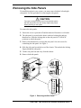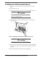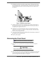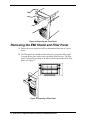
1
Express5800/120Ee
DDS-4 DAT Tape Drive/
SCSI Controller
Installation Insert
PN: 455-01660-000
Proprietary Notice and Liability Disclaimer
The information disclosed in this document, including all designs and related materials, is
the valuable property of NEC Solutions (America), Inc. and/or its licensors. NEC Solutions
(America), Inc. and/or its licensors, as appropriate, reserve all patent, copyright and other
proprietary rights to this document, including all design, manufacturing, reproduction, use,
and sales rights thereto, except to the extent said rights are expressly granted to others.
The NEC Solutions (America), Inc. product(s) discussed in this document are warranted in
accordance with the terms of the Warranty Statement accompanying each product.
However, actual performance of each product is dependent upon factors such as system
configuration, customer data, and operator control. Since implementation by customers of
each product may vary, the suitability of specific product configurations and applications
must be determined by the customer and is not warranted by NEC Solutions (America), Inc.
To allow for design and specification improvements, the information in this document is
subject to change at any time, without notice. Reproduction of this document or portions
thereof without prior written approval of NEC Solutions (America), Inc. is prohibited.
Trademarks
Adaptec is a registered trademark of Adaptec Incorporated.
Sony is a trademark of Sony Corporation.
All other product, brand, or trade names used in this publication are the trademarks or registered trademarks
of their respective trademark owners.
August 2002
Copyright 2002
NEC Solutions (America), Inc
15 Business Park Way
Sacramento, CA 95828
All Rights Reserved
Contents
Introduction ..................................................................................................................1
Unpacking the Option...................................................................................................1
General Information .....................................................................................................1
Static Precautions .........................................................................................................2
Preparing Your System for Option Installation............................................................2
Removing the Side Panels ............................................................................................3
Installing the SCSI Controller Board............................................................................4
Removing the Front Panel ............................................................................................5
Removing the EMI Shield and Filler Panel..................................................................6
Installing the DDS-4 DAT Tape Drive.........................................................................7
Introduction
This installation insert provides information for installing the Sony™
SDT-11000 DDS-4 DAT Tape Drive and Adaptec® SCSI controller into your
Express5800/120Ee Server. Read this procedure in its entirety before
performing the installation to become familiar with the components and the
sequence of steps you will perform.
Unpacking the Option
When you receive your option, inspect the shipping container prior to
unpacking. If the shipping box is damaged, note the damage, and if possible,
photograph it for reference. After removing the contents of the container, keep
the carton and the packing materials. If the contents appear damaged when you
unpack the box, file a damage claim with the carrier immediately.
The following components are included with this option:
!
Sony SDT-11000 DDS-4 DAT Tape Drive with mounting screws (4)
!
Adaptec ASC29160 SCSI Controller with mounting screw (1)
!
Terminated interface ribbon cable
!
This installation procedure.
General Information
! WARNING
The DC push-button on/off switch on the front panel does
not turn off the system AC power. Also, +5vdc is present on
the system board whenever the AC power cord is connected
between the system and an AC outlet. Before doing the
procedures in this manual, make sure that your system is
powered off and unplug the AC power cord from the back of
the chassis. Failure to disconnect power before opening
your system can result in personal injury and equipment
damage.
! CAUTION
The server management logic on your system board
monitors and logs system voltage changes. When powering
down your system you may experience a 1–5 second delay
from the time you press the push-button power on/off switch
on the front panel and your system powering down. This is
normal system operation and is required by the server
management logic.
DDS-4 DAT Tape Drive/SCSI Controller Installation Insert
1
! CAUTION
Operating your system with the side panels removed can
damage your system components. For proper cooling and
airflow, always replace the side panels before powering on
your system.
Static Precautions
An electrostatic discharge (ESD) can damage disk drives, option boards, and
other components. You can provide some ESD protection by wearing an
antistatic wrist strap attached to chassis ground when handling system
components.
Electronic devices can be easily damaged by static electricity. To prevent
damage, keep them in their protective packaging when they are not installed in
your system.
Preparing Your System for Option Installation
To prepare your system for installation of this option, perform the following
procedure:
1. Observe the safety and ESD precautions listed under General Information
and Static Precautions at the beginning of this chapter.
2. Shutdown the operating system (OS).
3. Press the power on/off switch on the front panel of the server. The power-on
LED goes out.
4. Power off the peripheral devices.
5. Unplug the system power cord from the AC wall outlet.
Note: If the system power cord is connected to a power
control unit such as an UPS (Uninterruptible Power Supply),
refer to the UPS user's guide for proper power-off
procedures.
2 DDS-4 DAT Tape Drive/SCSI Controller Installation Insert
Removing the Side Panels
To install this option in your system, you must remove both the left and right
side panels. Use this procedure for removing the side panels.
! CAUTION
For proper cooling and airflow, do not operate the system
with the side panels removed. Always replace the panels
before powering on the system.
To remove the side panels:
1. Ensure the server is powered off and disconnected from the ac wall outlet.
2. The side panel is secured to the chassis with two locking tabs and two
thumbscrews. Slide the locking tabs on the side panel to "UNLOCK"
positions to unlock the panel.
3. Remove the thumbscrews securing the side panel. Save the screws for
reattaching the side panel. See Figure 1.
4. Slide the side panel toward the rear of the chassis. This unlocks the locking
fingers behind the side panel.
5. Tilt the side panel out and away from the chassis.
6. Remove both side panels.
2
1
Unlock
Lock
Lock
Unlock
Figure 1. Removing the Side Panel
DDS-4 DAT Tape Drive/SCSI Controller Installation Insert
3
Installing the SCSI Controller Board
1. Ensure the server is powered off it is disconnected from the AC power
source.
2. Tilt the server on its side.
3. From the top of the system count down to the fourth expansion slot cover.
! CAUTION
Before performing the next step, be sure you are removing
th
the 4 expansion slot cover (as counted from the top of the
system). Once expansion slot covers are removed from the
system, they cannot be replaced.
4. Using a flat blade screwdriver, bend and remove the 4th expansion slot
cover. See Figure 2.
1 2
3 4
5
6
7
Figure 2. Removing the Fourth Expansion Slot Screw and Cover
! CAUTION
Observe static precautions. Use an antistatic wrist strap.
4. Remove the SCSI controller board from its protective wrapper, holding the
board only by the edges. Do not touch the board components or the gold
connectors.
5. Record the option board serial number in the equipment log.
4 DDS-4 DAT Tape Drive/SCSI Controller Installation Insert
6. Holding the board by its top edge or upper corners, firmly press the board
into an expansion slot 3 on the system board. The tapered foot of the option
board-retaining bracket must fit into the mating slot in the expansion slot.
See Figure 3.
Figure 3. Installing an Option Board
7. Align the rounded notch in the retaining bracket with the threaded hole in
the expansion slot frame. The retaining bracket fits into the space that was
occupied by the expansion slot cover.
8. Install the screw in the threaded hole. Be sure to push the bracket slot up
against the screw before you tighten it. If this is not done, the bracket may
interfere with an adjacent bracket.
9. Connect the P1 end of the interface ribbon cable to the primary connector of
the installed SCSI controller board.
10. Tip the system upright.
Removing the Front Panel
Note: The front panel is secured with six locking tabs.
1. Ensure the server is powered off it is disconnected from the AC power
source.
! CAUTION
Observe static precautions. Use an antistatic wrist strap.
2. Remove the front panel by first releasing the three tabs that secure the panel
to the left side of the system chassis. Then release the tabs that secure the
panel to the right side of the chassis. See Figure 4.
DDS-4 DAT Tape Drive/SCSI Controller Installation Insert
5
Figure 4. Removing the Front Panel
Removing the EMI Shield and Filler Panel
1. Ensure the server is powered off it is disconnected from the AC power
source.
2. The filler panels are attached to the front cover. Locate the filler panel
covering the bay into which you are installing DDS-4 device. The filler
panel is released by pressing on its tabs located on the inside of the front
panel. See Figure 5.
Figure 5. Removing a Filler Panel
6 DDS-4 DAT Tape Drive/SCSI Controller Installation Insert
3. Locate the EMI (Electromagnetic Interference) shield covering the bay into
which you are installing the DDS-4 device The EMI shield is attached to the
front of the chassis with two screws. Remove the screws and EMI shield
covering the bay into which you are installing a peripheral device. See
Figure 6.
Figure 6. Removing an EMI Shield
Installing the DDS-4 DAT Tape Drive
1. Ensure the server is powered off it is disconnected from the AC power
source.
! CAUTION
Observe static precautions. Use an antistatic wrist strap.
2. Remove the DDS-4 DAT tape device from its protective wrapper and place
it on an antistatic surface. Record the drive model and serial number in the
equipment log.
3. Set any drive jumpers or switches before you install the drive. See the
documentation that comes with the device for jumper or switch information.
Note: If the drive comes with drive rails, do not use
them. Remove any rails already attached.
4. Slide the drive into the bay until the screw holes line up. Align the front
panel of the installed device with the CDROM drive. It may be necessary to
temporarily loosen the mounting screws on already installed drives to
position the new drive. Secure the drive to the bay with the four supplied
mounting screws. See Figure 7.
DDS-4 DAT Tape Drive/SCSI Controller Installation Insert
7
Power Cable
Figure 7. Installing a Removable Media Device
5. Connect the P2 end of the interface ribbon cable and the power cable to the
device as shown in Figure 7.
6. Replace the front panel and side panels, and power on the system.
8 DDS-4 DAT Tape Drive/SCSI Controller Installation Insert