1
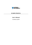
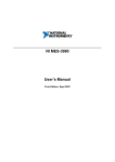
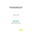
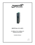
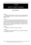
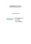
NI UES-3880
Hardware Installation Guide
First Edition, Sept 2007
P/N: 1802003080110
Overview
The NI UES-3880 is a smart Ethernet switch that provides an economical
solution for your Ethernet connections. As an added bonus, the built-in smart
alarm function helps system maintainers monitor the health of your Ethernet
network.
The NI UES-3880 has a wide operating temperature range of -40 to 75ºC, and
is designed to withstand a high degree of vibration and shock. The rugged
hardware design makes either model perfect for ensuring that your Ethernet
equipment can withstand critical industrial applications, and complies with
FCC and CE Standards.
Package Checklist
Your NI UES-3880 is shipped with the following items. If any of these items
are missing or damaged, please contact your customer service representative
for assistance.
y NI UES-3880 Switch
y Hardware Installation Guide
y Protective caps for unused ports
Features
High Performance Network Switching Technology
y 10/100BaseT(X) (RJ45)
y IEEE802.3/802.3u/802.3x
y Store and Forward switching process type, with 1024 address entries
y 10/100M, Full/Half-Duplex, MDI/MDIX auto-sensing
Industrial Grade Reliability
y Power failure, port break alarm by relay output
y Redundant dual DC power inputs
Rugged Design
y Operating temperature range from -40 to 75ºC
y IP30, rugged high-strength case
y DIN-rail or panel mounting ability
WARNING
The power for this product is intended to be supplied by a Listed
Power Supply, with output marked LPS, and rated to deliver 12 to
48 VDC at a maximum of 0.6A.
The DC jack should be used with an LPS unit that is rated to
deliver 12 to 48 VDC at a minimum of 1.1A. The product should
not be disassembled by operators or service people.
— 1 —
Panel Layout
Front Panel View
2
1.
5
6
7
2.
Grounding screw
Terminal block for power inputs
PWR1/PWR2 and relay output
11
8
3.
Heat dissipation orifices
4.
DIP switches
5.
Power input PWR1 LED
6.
Power input PWR2 LED
7.
Fault LED
9
8.
10/100BaseT(X) Port
10
9.
TP port’s 100 Mbps LED
10. TP port’s 10 Mbps LED
Top Panel View
11. Model Name
12. Screw holes for wall mounting kit
1
V2+
13. DIN-rail Kit
PWR2
V2-
2
FAULT
V1+
PWR1
V1V1 V2 INPUTS: 24 VDC
3
PORT ALARM
1
2
ON
3
4
5
6
8
DIP
7
4
Rear Panel View
2
1
12
13
12
— 2 —
Mounting Dimensions (unit = mm)
21.00 30.00
54.00
9.50
Side View
135.00
(unit = mm)
105.00
25.71
15.10
13.10
25.40
+
39.37
+
13.90 18.20 13.90
9.75
3.50
+
+
6
+
+
6.00
26
+
3.50 +
10
+
+
6.00
10
+
+
5
30.50
7.75
7.75
13
18
13
23.15
46.77
135.00
Front View
+
+
+
+
+
+
+
+
+
+
Rear View
— 3 —
+
+
Panel Mount Kit
DIN-rail Mounting
The aluminum DIN-rail attachment plate should already be fixed to the back
panel of the switch when you take it out of the box. If you need to reattach the
DIN-rail attachment plate, make sure the stiff metal spring is situated towards
the top, as shown in the figures below.
STEP 1:
Insert the top of the DIN-rail into the
slot just below the stiff metal spring.
STEP 2:
The DIN-rail attachment unit will
snap into place as shown below.
metal
spring
metal
spring
DIN-Rail
DIN-Rail
To remove the switch from the DIN-rail, simply reverse Steps 1 and 2 above.
Wall Mounting (optional)
For some applications, you will find it convenient to mount the NI UES-3880
on the wall, as illustrated below.
STEP 1:
Remove the aluminum
DIN-rail attachment plate
from the NI UES-3880’s rear
panel, and then attach the
wall mount plates, as shown
in the diagram below.
top
plate
⇒
bottom
plate
STEP 2:
6.0 mm
Mounting the NI UES-3880 on the wall requires 4 screws.
Use the switch, with wall mount plates attached, as a guide
to mark the correct locations of the 4 screws. The heads of
the screws should be less than 6.0 mm in diameter, and the
shafts should be less than 3.5 mm in diameter, as shown in 3.5 mm
the figure at the right.
NOTE Before tightening the screws into the wall, make sure the screw head
and shank size are suitable by inserting the screw into one of the
keyhole-shaped apertures of the Wall Mounting Plates.
Do not screw the screws in all the way—leave about 2 mm to allow room for
sliding the wall mount panel between the wall and the screws.
— 4 —
STEP 3:
Once the screws are fixed in the
wall, insert the four screw heads
through the large parts of the
keyhole-shaped apertures, and then
slide the NI UES-3880
downwards, as indicated. Tighten
the four screws for added stability.
⇒
Wiring Requirements
WARNING
Do not disconnect modules or wires unless the power supply has
been switched off or the area is known to be non-hazardous. The
devices may only be connected to the supply voltage shown on
the type plate.
The devices are designed for operation with a Safety Extra-Low
Voltage. Thus, they may only be connected to the supply voltage
connections and to the signal contact with the Safety Extra-Low
Voltages (SELV) in compliance with IEC950/ EN60950/
VDE0805.
WARNING
Substitution of components may impair suitability for Class I,
Division 2, and Zone 2. These devices must be supplied by an
SELV source as defined in Low Voltage Directive 73/23/EEC
and 93/68/EEC.
WARNING
This unit is a built-in type. When the unit is installed in another
piece of equipment, the equipment enclosing the unit must
comply with fire enclosure regulation IEC 60950/EN60950 (or
similar regulation).
WARNING
Safety First!
Be sure to disconnect the power cord before installing and/or
wiring your Switch.
Calculate the maximum possible current in each power wire and
common wire. Observe all electrical codes dictating the
maximum current allowable for each wire size.
If the current goes above the maximum ratings, the wiring could
overheat, causing serious damage to your equipment.
— 5 —
You should also pay attention to the following items:
y Use separate paths to route wiring for power and devices. If power wiring
and device wiring paths must cross, make sure the wires are perpendicular
at the intersection point.
y NOTE: Do not run signal or communications wiring and power wiring in
the same wire conduit. To avoid interference, wires with different signal
characteristics should be routed separately.
y You can use the type of signal transmitted through a wire to determine
which wires should be kept separate. The rule of thumb is that wiring that
shares similar electrical characteristics can be bundled together.
y Keep input wiring and output wiring separated.
y It is strongly advised that you label wiring to all devices in the system when
necessary.
Grounding the Switch
Grounding and wire routing help limit the effects of noise due to
electromagnetic interference (EMI). Run the ground connection from the
ground screw to the grounding surface prior to connecting devices.
ATTENTION
This product is intended to be mounted to a well-grounded
mounting surface, such as a metal panel.
Wiring the Alarm Contact
The Alarm Contact consists of the two middle contacts of the terminal block on
the NI UES-3880’s top panel. You may refer to the next section for detailed
instructions on how to connect the wires to the terminal block connector, and
how to attach the terminal block connector to the terminal block receptor. In
this section, we explain the meaning of the two contacts used to connect the
Alarm Contact.
FAULT
Top View
FAULT
Front View
FAULT: The two middle contacts of the
6-contact terminal block connector are used to
detect both power faults and port faults. The two
wires attached to the Fault contacts form an open
circuit when:
1. The NI UES-3880 has lost power from one of
the DC power inputs.
OR
2. One of the ports for which the corresponding
PORT ALARM DIP Switch is set to ON is
not properly connected.
If neither of these two conditions is satisfied, the
Fault circuit will be closed.
Wiring the Redundant Power Inputs
The top two contacts and the bottom two contacts of the 6-contact terminal
block connector on the NI UES-3880’s top panel are used for the NI
UES-3880’s two DC inputs. Top and front views of one of the terminal block
connectors are shown here.
— 6 —
STEP 1: Insert the negative/positive DC wires
into the V-/V+ terminals.
Top View
STEP 2: To keep the DC wires from pulling
loose, use a small flat-blade screwdriver to
tighten the wire-clamp screws on the front of the
terminal block connector.
Front View
STEP 3: Insert the plastic terminal block
connector prongs into the terminal block
receptor, which is located on the NI UES-3880’s
top panel.
ATTENTION
Before connecting the NI UES-3880 to the DC power inputs,
make sure the DC power source voltage is stable.
10/100BaseT(X) Ethernet Port Connection
The 10/100BaseT(X) ports located on the NI UES-3880’s front panel are used
to connect to Ethernet-enabled devices.
Below we show pinouts for both MDI (NIC-type) ports and MDI-X
(HUB/Switch-type) ports, and also show cable wiring diagrams for
straight-through and cross-over Ethernet cables.
MDI Port Pinouts
Pin
1
2
3
6
Signal
Tx+
TxRx+
Rx-
MDI-X Port Pinouts
Pin
1
2
3
6
Signal
Rx+
RxTx+
Tx-
8-pin RJ45
1
8
RJ45 (8-pin) to RJ45 (8-pin) Straight-Through Cable Wiring
Straight-Through Cable
Switch Port
RJ45
Connector
Tx+
TxRx+
Rx-
NIC Port
RJ45 Plug Pin 1
RJ45
Connector
Cable Wiring
3
6
1
2
3
6
1
2
— 7 —
Rx+
RxTx+
Tx-
RJ45 (8-pin) to RJ45 (8-pin) Cross-Over Cable Wiring
Cross-Over Cable
Switch Port
(NIC Port)
RJ45 Plug Pin 1
RJ45
Connector
(Rx+)
(Rx-)
(Tx+)
(Tx-)
Switch Port
(NIC Port)
RJ45
Connector
Cable Wiring
Tx+
TxRx+
Rx-
3
6
1
2
1
2
3
6
Rx+
RxTx+
Tx-
(Tx+)
(Tx-)
(Rx+)
(Rx-)
Redundant Power Inputs
Both power inputs can be connected simultaneously to live DC power sources.
If one power source fails, the other live source acts as a backup, and
automatically supplies all of the NI UES-3880’s power needs.
Alarm Contact
The NI UES-3880 has one Alarm Contact located on the top panel. For detailed
instructions on how to connect the Alarm Contact power wires to the two
middle contacts of the 6-contact terminal block connector, see the Wiring the
Alarm Contact section. A typical scenario would be to connect the Fault circuit
to a warning light located in the control room. The light can be set up to switch
on when a fault is detected.
The Alarm Contact has two terminals that form a Fault circuit for connecting to
an alarm system. The two wires attached to the Fault contacts form an open
circuit when (1) the NI UES-3880 has lost power from one of the DC power
inputs, or (2) one of the ports for which the corresponding PORT ALARM DIP
Switch is set to ON is not properly connected.
If neither of these two conditions occurs, the Fault circuit will be closed.
DIP Switch Settings
ON
1
2
DIP
3
4
5
6
7
8
ON: Enables the corresponding PORT Alarm. If the port’s link fails, the relay
will form an open circuit and the fault LED will light up.
Off: Disables the corresponding PORT Alarm. The relay will form a closed
circuit and the Fault LED will never light up.
— 8 —
LED Indicators
The front panel of the NI Switch contains several LED indicators. The function
of each LED is described in the table below.
LED
PWR1
PWR2
FAULT
10M
100M
Color
State
On
Off
Power is not being supplied to power
input PWR1
On
Power is being supplied to power input
PWR2
Off
Power is not being supplied to power
input PWR2
On
When the corresponding PORT alarm is
enabled, and the port’s link is inactive.
Off
When the corresponding PORT alarm is
enabled and the port’s link is active, or
when the corresponding PORT alarm is
disabled.
On
TP port’s 10 Mbps link is active
AMBER
AMBER
RED
GREEN
GREEN
Description
Power is being supplied to power input
PWR1
Blinking Data is being transmitted at 10 Mbps
Off
TP Port’s 10 Mbps link is inactive
On
TP port’s 100 Mbps link is active
Blinking Data is being transmitted at 100 Mbps
Off
TP Port’s 100 Mbps link is inactive
Auto MDI/MDI-X Connection
The Auto MDI/MDI-X function allows users to connect the NI UES-3880’s
10/100BaseTX ports to any kind of Ethernet device, without needing to pay
attention to the type of Ethernet cable being used for the connection. This
means that you can use either a straight-through cable or cross-over cable to
connect the NI UES-3880 to Ethernet devices.
Dual Speed Functionality and
Switching
The NI UES-3880’s 10/100 Mbps switched RJ45 port auto-negotiates with the
connected device for the fastest data transmission rate supported by both
devices. The NI UES-3880 is a plug-and-play devices, so that software
configuration is not required at installation, or during maintenance. The
half/full duplex mode for the switched RJ45 ports is user dependent and
changes (by auto-negotiation) to full or half duplex, depending on which
transmission speed is supported by the attached device.
Switching, Filtering, and Forwarding
Each time a packet arrives at one of the switched ports, a decision is made to
either filter or forward the packet. Packets with source and destination
addresses belonging to the same port segment will be filtered, constraining
those packets to one port, and relieving the rest of the network from the need to
process them. A packet with destination address on another port segment will
be forwarded to the appropriate port, and will not be sent to the other ports
— 9 —
where it is not needed. Packets that are used in maintaining the operation of the
network (such as the occasional multi-cast packet) are forwarded to all ports.
The NI UES-3880 operates in the store-and-forward switching mode, which
eliminates bad packets and enables peak performance to be achieved when
there is heavy traffic on the network.
Switching and Address Learning
The NI UES-3880 has an address table that can hold up to 1K node addresses,
which makes it suitable for use with large networks. The address tables are
self-learning, so that as nodes are added or removed, or moved from one
segment to another, the NI UES-3880 automatically keeps up with new node
locations. An address-aging algorithm causes the least-used addresses to be
deleted in favor of newer, more frequently used addresses. To reset the address
buffer, power down the unit and then power it back up.
Auto-Negotiation and Speed Sensing
The NI UES-3880 is a RJ45 Ethernet ports independently support
auto-negotiation for speeds in the 10BaseT and 100BaseTX modes, with
operation according to the IEEE 802.3u standard. This means that some nodes
could be operating at 10 Mbps, while at the same time, other nodes are
operating at 100 Mbps.
Auto-negotiation takes place when an RJ45 cable connection is made, and then
each time a LINK is enabled. The NI UES-3880 advertises its capability for
using either 10 Mbps or 100 Mbps transmission speeds, with the device at the
other end of the cable expected to similarly advertise. Depending on what type
of device is connected, this will result in agreement to operate at a speed of
either 10 Mbps or 100 Mbps.
If the NI UES-3880 RJ45 Ethernet port is connected to a non-negotiating
device, it will default to 10 Mbps speed and half-duplex mode, as required by
the IEEE 802.3u standard.
— 10 —
Specifications
Technology
Standards
Forward and Filtering
Rate
Packet Buffer Memory
Processing Type
Address Table Size
Latency
Interface
RJ45 Ports
LED Indicators
DIP Switch
Alarm Contact
Power
Input Voltage
Input Current @ 24VDC
Connection
Overload Current
Protection
Reverse Polarity
Protection
Mechanical
Casing
Dimensions
Weight
Installation
Environmental
Operating Temperature
Storage Temperature
Ambient Relative
Humidity
Regulatory Approvals
Safety
Hazardous Location
EMI
EMS
Operating Shock
Operating Vibration
IEEE802.3, 802.3u, 802.3x
148810 pps
256 KB
Store and Forward, with IEEE802.3x full duplex,
back pressure flow control
1K uni-cast addresses
Less than 5 μs
10/100BaseT(X) auto negotiation speed, F/H duplex
mode, and auto MDI/MDI-X connection
Power, Fault, 10M, 100M
Port break alarm mask
One relay output with current carrying capacity of
1A @ 24 VDC
12 to 48 VDC, redundant inputs
0.25 A
Removable “6-pin” Terminal Block
1.1 A
Present
IP30 protection, metal case
53.6 × 135 × 105 mm (W × H × D)
0.63 kg
DIN-rail, Wall Mounting
-40 to 75ºC (-40 to 167ºF)
-40 to 85ºC (-40 to 185ºF)
5 to 95% (non-condensing)
UL60950-1, CSA C22.2 No. 60950-1, EN60950-1,
TUV
UL/cUL Class I, Division 2, Groups A, B, C, and D
FCC Part 15, CISPR (EN55022) class A
EN61000-4-2 (ESD), Level 3
EN61000-4-3 (RS), Level 3
EN61000-4-4 (EFT), Level 3
EN61000-4-5 (Surge), Level 3
EN61000-4-6 (CS), Level 3
15g, half-sine, 11 ms pulse
10 Hz to 150 Hz, 1 grms
— 11 —
Technical Support and Professional
Services
Visit the following sections of the National Instruments Web site at ni.com for
technical support and professional services:
• Support— Online technical support resources at ni.com/support include
the following:
Self-Help Resources— For answers and solutions, visit the
award-winning National Instruments Web site for software drivers and
updates, a searchable KnowledgeBase, product manuals, step-by-step
troubleshooting wizards, thousands of example programs, tutorials,
application notes, instrument drivers, and so on.
Free Technical Support— All registered users receive free Basic
Service, which includes access to hundreds of Application Engineers
worldwide in the NI Discussion Forums at ni.com/forums. National
Instruments Application Engineers make sure every question receives
an answer.
For information about other technical support options in your area, visit
ni.com/services or contact your local office at ni.com/contact.
• Training and Certification— Visit ni.com/training for self-paced training,
eLearning virtual classrooms, interactive CDs, and Certification program
information. You also can register for instructor-led, hands-on courses at
locations around the world.
• System Integration— If you have time constraints, limited in-house
technical resources, or other project challenges, National Instruments
Alliance Partner members can help. To learn more, call your local NI office
or visit ni.com/alliance.
• Declaration of Conformity (DoC)— A DoC is our claim of compliance
with the Council of the European Communities using the manufacturer’s
declaration of conformity. This system affords the user protection for
electronic compatibility (EMC) and product safety. You can obtain the DoC
for your product by visiting ni.com/certification.
• Calibration Certificate— If your product supports calibration, you can
obtain the calibration certificate for your product at ni.com/calibration.
If you searched ni.com and could not find the answers you need, contact your
local office or NI corporate headquarters. Phone numbers for our worldwide
offices are listed at the front of this manual. You also can visit the Worldwide
Offices section of ni.com/niglobal to access the branch office Web sites, which
provide up-to-date contact information, support phone numbers, email
addresses, and current events.
— 12 —
Worldwide Technical Support and Product Information
ni.com
National Instruments Corporate Headquarters
11500 North Mopac ExpresswayAustin, Texas 78759-3504USATel: 512 683
0100
Worldwide Offices
Australia 1800 300 800, Austria 43 662 457990-0, Belgium 32 (0) 2 757 0020,
Brazil 55 11 3262 3599, Canada 800 433 3488, China 86 21 5050 9800, Czech
Republic 420 224 235 774, Denmark 45 45 76 26 00, Finland 358 (0) 9 725
72511, France 01 57 66 24 24, Germany 49 89 7413130, India 91 80 41190000,
Israel 972 3 6393737, Italy 39 02 413091, Japan 81 3 5472 2970, Korea 82 02
3451 3400, Lebanon 961 (0) 1 33 28 28, Malaysia 1800 887710, Mexico 01
800 010 0793, Netherlands 31 (0) 348 433 466, New Zealand 0800 553 322,
Norway 47 (0) 66 90 76 60, Poland 48 22 3390150, Portugal 351 210 311 210,
Russia 7 495 783 6851, Singapore 1800 226 5886, Slovenia 386 3 425 42 00,
South Africa 27 0 11 805 8197, Spain 34 91 640 0085, Sweden 46 (0) 8 587
895 00, Switzerland 41 56 2005151, Taiwan 886 02 2377 2222, Thailand 662
278 6777, Turkey 90 212 279 3031, United Kingdom 44 (0) 1635 523545
For further support information, refer to the Cross referenceolor:Blueparatext
appendix. To comment on National Instruments documentation, refer to the
National Instruments Web site at ni.com/info and enter the info code feedback.
© 2007 National Instruments Corporation. All rights reserved.
— 13 —