1
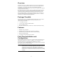
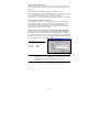
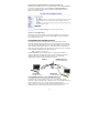
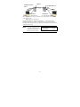
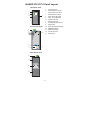
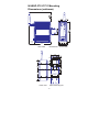
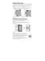
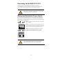
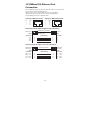
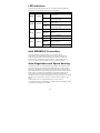
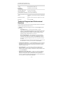
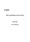
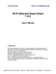
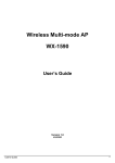
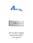
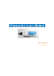
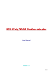
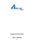
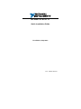
NI WAP-3701/3711
Quick Installation Guide
First Edition, Sept 2007
P/N: 1802011000110
Overview
The NI WAP-3701/3711 enables wireless users to access network resources
wirelessly. It can authenticate and authorize wireless users by IEEE 802.1X
and RADIUS, and communicates with a back-end RADIUS (Remote
Authentication User Dial-In Service) server to see if a wireless user is allowed
to access the wireless network.
The NI WAP-3701/3711 is rated to operate at temperatures ranging from 0 to
60°C, and is rugged enough for any harsh industrial environment. It can be
installed easily using either DIN-Rail mounting or distribution boxes. The
DIN-rail mounting ability, wide operating temperature range, and IP30 case
with LED indicators make the plug-and-play NI WAP-3701/3711 a reliable
solution for your industrial wireless applications.
Package Checklist
The NI WAP-3701/3711 is shipped with the following items. If any of these
items is missing or damaged, please contact your customer service
representative for assistance.
y 1 × NI WAP-3701/3711
y 2 × Swivel Type Antenna (2 dBi RP-SMA)
y Quick Installation Guide
y Document & Software CD; includes User’s Manual and Windows Utility
Features
y IEEE 802.11b/g Compliant
y Redundant 24 VDC power inputs or Power-over-Ethernet
y Powerful security with WPA/802.1X/MAC address filtering
y DIN-Rail mounting ability
y Case design meets IP30 protection standard
First-Time Installation and
Configuration
Before installing the NI WAP-3701/3711, check to make sure that all items in
the Package Checklist are in the box. In addition, you will need access to a
notebook computer or PC equipped with an Ethernet port. The NI
WAP-3701/3711 has a default IP address that you must use when connecting to
the NI WAP-3701/3711 for the first time.
NOTE
For testing requirements, if you only have one NI
WAP-3701/3711, we strongly suggest that you prepare a notebook
computer or PC with a wireless LAN adapter installed. After
finishing the installation and configuration, you should test the NI
WAP-3701/3711 to make sure the wireless transmission is working
normally.
-1-
Step 1: Select the Power Source
The NI WAP-3701/3711 can be powered by a DC power input, or by PoE
(Power over Ethernet). The NI WAP-3701/3711 will use the power source that
you select.
Step 2: Connect the NI WAP-3701/3711 to a notebook or PC
Since the NI WAP-3701/3711 supports MDI/MDI-X auto-sensing, you can use
either a straight-through cable or cross-over cable to connect the NI
WAP-3701/3711 to the notebook. If the LAN LED on the NI
WAP-3701/3711’s front panel lights up, it means the connection is established.
Step 3: Set up the computer’s IP address
In a Windows environment, the computer’s IP address can be changed in the
TCP/IP settings window. Select an IP address on the same subnet as the NI
WAP-3701/3711. Since the NI WAP-3701/3711’s default IP address is
192.168.127.253, and the subnet mask is 255.255.255.0, you should set the IP
address of the computer to 192.168.127.xxx.
Step 4: Use the web-based manager to configure the NI WAP-3701/3711
Open your computer’s web browser and then type http://192.168.127.253 in
the address box to access the homepage of the web-based Network Manager.
Before the homepage opens, you will need to enter the user name and password
as shown in the following figure. For first-time configuration, enter the default
user name and password and then click on OK:
Default user name & password
192.168.127.253
User name:
Password:
NOTE
admin
root
For security reasons, we strongly recommend changing the
password. To do so, open the Network Manager homepage, click
on General Æ Password, and then follow the onscreen
instructions.
-2-
Step 5: Select the operation mode for the NI WAP-3701/3711
By default, the NI WAP-3701/3711’s operation mode is set to Access Point. If
you want to change the setting, click on General Æ Operation Mode, as
shown in the following figure, select an operation mode, and then click on
Save to activate the change.
Step 6: Test communications
We describe two testing methods. Use the first method if you are using only
one NI WAP-3701/3711, and use the second method if you are using two or
more NI WAP-3701/3711s.
Testing Method for one NI WAP-3701/3711
If you are only using one NI WAP-3701/3711, you will need a second
notebook computer equipped with a WLAN card. Configure the WLAN card
for connecting to the NI WAP-3701/3711 (the default SSID is NI), and change
the IP address of notebook B so that it is on the same subnet as notebook A.
After connecting the WLAN card, connect to the NI WAP-3701/3711 and open
a DOS window on notebook B. At the prompt, type
ping IP address of notebook A
and then press Enter (see the figure below). A “Reply from IP address …”
response means the communication was successful. A “Request timed out.”
response means the communication failed. In this case, recheck the
configuration to make sure the connections are correct.
NI WAP-3701/3711
IP: 192.168.127.253
SSID: NI
PING
Notebook B
IP: 192.168.127.1
Notebook A
IP: 192.168.127.2
Testing Method for two or more NI WAP-3701/3711s
If you have two or more NI WAP-3701/3711’s, you will need a second
notebook computer equipped with an Ethernet port. Use the default settings for
the first NI WAP-3701/3711’s, and change the second or third NI
WAP-3701/3711 to AP Client mode. Use the network settings shown in the
following figure to configure the notebook and NI WAP-3701/3711.
-3-
SSID: NI
NI WAP-3701/3711 /
Client
NI WAP-3701/3711
/ AP
PING
Notebook A
IP: 192.168.127.2
Notebook B
IP: 192.168.127.1
After setting up the testing environment, open a DOS window on notebook B.
At the prompt, type
ping IP address of notebook A
and then press Enter. A “Reply from IP address …” response means the
communication was successful. A “Request timed out.” response means the
communications failed. In this case, recheck the configuration to make sure the
connections are correct.
NOTE
Use the Link Monitor feature
on the AP Client side to help
confirm the wireless link
quality and signal strength.
-4-
NI WAP-3701/3711 Panel Layout
Top Panel View
1.
2.
1
3
14
Front Panel View
3.
Heat dissipation orifices
4.
Power input PWR1 LED
5.
Power input PWR2 LED
6.
Wireless LAN LED
7.
Ethernet LAN LED
8.
10/100BaseT(X) RJ45 Port
9.
Model Name
10. Screw hole for wall mounting kit
11. DIN-Rail mounting kit
2
12. MAIN antenna port
12
13. AUX antenna port
14. Reset button
9
8
Terminal block for power
inputs PWR1 and PWR2
2
4
5
6
7
Grounding screw
13
Rear Panel View
2
10
11
10
-5-
NI WAP-3701/3711 Mounting
Dimensions (unit=mm)
30.29
(1.19)
105.00
(4.13)
Side View
DIN-Rail Kit
Front View
46.00
3.5
6
66.80
6
13.90 18.20 13.90
10
25.71
57.05
10
5
13
39.37
44
18
13
48.30
27.20
46.77
7.75
30.50
7.75
23.15
Rear View
Panel Mounting Kit
-6-
DIN-Rail Mounting
The aluminum DIN-Rail attachment plate should be fixed to the back panel of
the NI WAP-3701/3711 when you take it out of the box. If you need to reattach
the DIN-Rail attachment plate to the NI WAP-3701/3711, make sure the stiff
metal spring is situated towards the top, as shown in the figures below.
STEP 1:
STEP 2:
Insert the top of the DIN-Rail into the The DIN-Rail attachment unit will snap
slot just below the stiff metal spring. into place as shown below.
metal
spring
metal
spring
DIN-Rail
DIN-Rail
To remove the NI WAP-3701/3711 from the DIN-Rail, simply reverse Steps 1
and 2 above.
Wall Mounting (Optional)
For some applications, you will find it convenient to mount the NI
WAP-3701/3711 on the wall, as illustrated below.
STEP 1:
Remove the aluminum DIN-Rail attachment plate from the NI
WAP-3701/3711, and then attach the wall mount plates, as shown in the
diagrams below.
Top
plate
⇒
Bottom
plate
STEP 2:
Mounting the NI WAP-3701/3711 on the wall requires 4
screws. Use the NI WAP-3701/3711, with wall mount plates
6.0 mm
attached, as a guide to mark the correct locations of the 4
screws. The heads of the screws should be less than 6.0 mm
in diameter, and the shafts should be less than 3.5 mm in
diameter, as shown in the figure at the right.
3.5 mm
Do not screw the screws in all the way—leave a space of
about 2 mm to allow room for sliding the wall mount panel
between the wall and the screws.
-7-
NOTE
Test the screw head and shank size by inserting the screw into one
of the keyhole shaped apertures of the Wall Mounting Plates,
before it is screwed into the wall.
STEP 3:
Once the screws are fixed in the wall, insert the four screw heads through the
large parts of the keyhole-shaped apertures, and then slide the NI
WAP-3701/3711 downwards, as indicated below. Tighten the four screws for
added stability.
Wiring Requirements
ATTENTION
ATTENTION
Safety First!
Be sure to disconnect the power cord before installing and/or
wiring your NI WAP-3701/3711.
Safety First!
Calculate the maximum possible current in each power wire
and common wire. Observe all electrical codes dictating the
maximum current allowable for each wire size.
If the current goes above the maximum ratings, the wiring
could overheat, causing serious damage to your equipment.
You should also pay attention to the following points:
y Use separate paths to route wiring for power and devices. If power wiring
and device wiring paths must cross, make sure the wires are perpendicular
at the intersection point.
NOTE: Do not run signal or communications wiring and power wiring in
the same wire conduit. To avoid interference, wires with different signal
characteristics should be routed separately.
y You can use the type of signal transmitted through a wire to determine
which wires should be kept separate. The rule of thumb is that wiring that
shares similar electrical characteristics can be bundled together.
y Keep input wiring and output wiring separated.
y It is strongly advised that you label wiring to all devices in the system when
necessary.
-8-
Grounding the NI WAP-3701/3711
Grounding and wire routing help limit the effects of noise due to
electromagnetic interference (EMI). Run the ground connection from the
ground screw to the grounding surface prior to connecting devices.
ATTENTION
This product is intended to be mounted to a well-grounded
mounting surface such as a metal panel.
Wiring the Redundant Power Inputs
The top two contacts and the bottom two contacts of the 4-contact terminal
block connector on the NI WAP-3701/3711’s top panel are used for the NI
WAP-3701/3711’s two DC inputs. Top and front views of one of the terminal
block connectors are shown here.
STEP 1: Insert the negative/positive DC wires into the
V-/V+ terminals.
STEP 2: To keep the DC wires from pulling loose, use
a small flat-blade screwdriver to tighten the wire-clamp
screws on the front of the terminal block connector.
Top View
STEP 3: Insert the plastic terminal block connector
prongs into the terminal block receptor, which is
located on the NI WAP-3701/3711’s top panel.
Front View
ATTENTION
Before connecting the NI WAP-3701/3711 to the DC power
inputs, make sure the DC power source voltage is stable.
-9-
10/100BaseT(X) Ethernet Port
Connection
The 10/100BaseT(X) ports located on the NI WAP-3701/3711’s front panel are
used to connect to Ethernet-enabled devices.
Below we show pinouts for both MDI (NIC-type) ports and MDI-X
(HUB/Switch-type) ports, and also show cable wiring diagrams for
straight-through and cross-over Ethernet cables.
RJ45 (8-pin, MDI) Port Pinouts
RJ45 (8-pin, MDI-X) Port Pinouts
Pin
Signal
Pin
Signal
1
2
3
6
Tx+
TxRx+
Rx-
1
2
3
6
Rx+
RxTx+
Tx-
1
8
1
8
RJ45 (8-pin) to RJ45 (8-pin) Straight-Through Cable Wiring
Straight-Through Cable
Switch Port
RJ45
Connector
Tx+
TxRx+
Rx-
NIC Port
RJ45 Plug Pin 1
RJ45
Connector
Cable Wiring
3
6
1
2
3
6
1
2
Rx+
RxTx+
Tx-
RJ45 (8-pin) to RJ45 (8-pin) Cross-Over Cable Wiring
Cross-Over Cable
Switch Port
(NIC Port)
RJ45 Plug Pin 1
RJ45
Connector
(Rx+)
(Rx-)
(Tx+)
(Tx-)
Tx+
TxRx+
Rx-
Switch Port
(NIC Port)
RJ45
Connector
Cable Wiring
3
6
1
2
1
2
3
6
- 10 -
Rx+
RxTx+
Tx-
(Tx+)
(Tx-)
(Rx+)
(Rx-)
LED Indicators
The front panel of the NI WAP-3701/3711 contains several LED indicators.
The function of each LED is described in the table below.
LED
PWR1
PWR2
WLAN
LAN
Color
State
On
Off
Power is not being supplied to
power input PWR1
On
Power is being supplied to power
input PWR2
Off
Power is not being supplied to
power input PWR2
On
RF port is active
AMBER
AMBER
GREEN
GREEN
Description
Power is being supplied to power
input PWR1
Blinking
Data is being transmitted via the
RF port
Off
RF port is inactive
On
LAN port is active
Blinking
Off
Data is being transmitted/received
via the LAN port
LAN port is inactive
Auto MDI/MDI-X Connection
The Auto MDI/MDI-X function allows users to connect the NI
WAP-3701/3711’s 10/100BaseTX ports to any kind of Ethernet device,
without paying attention to the type of Ethernet cable being used for the
connection. This means that you can use either a straight-through cable or
cross-over cable to connect NI WAP-3701/3711 to Ethernet devices.
Auto-Negotiation and Speed Sensing
The NI WAP-3701/3711’s RJ45 Ethernet port supports auto-negotiation for
transmission speeds in the 10BaseT and 100BaseTX modes, with operation
according to the IEEE 802.3u standard. Auto-negotiation takes place when an
RJ45 cable connection is made, and then each time a LINK is enabled. The NI
WAP-3701/3711 advertises its capability for using either 10 Mbps or 100
Mbps transmission speeds, with the device at the other end of the cable
expected to advertise similarly. Depending on what type of device is connected,
this will result in agreement to operate at a speed of either 10 Mbps or 100
Mbps.
If the NI WAP-3701/3711’s RJ45 Ethernet port is connected to a
non-negotiating device, it will default to 10 Mbps speed and half-duplex mode,
as required by the IEEE 802.3u standard.
- 11 -
Specifications
WLAN
Standards
Frequency Range
Data Rate & Modulation
Operating Channels
Security
Data Rates
IEEE802.11g/b for wireless LAN, IEEE802.3u
10/100BaseTX for Ethernet LAN, IEEE802.3af for
Power over Ethernet
2.4-2.4835 GHz, Direct Sequence Spread
Spectrum (DSSS)
OFDM@54Mbps, CCK@11/5.5Mbps,
DQPSK@2Mbps and DBSK@1Mbps
USA: 1-11 (FCC) / Europe: 1-13 (ETSI)
64-bit and 128-bit WEP encryption, WPA (IEEE
802.1X/RADIUS and TKIP)
1, 2, 5.5, 6, 9, 11, 12, 18, 24, 36, 48, 54 Mbps
Transmit Power
802.11b:
≥17dBm
802.11g:
6/9Mbps≥17dBm, 12/18Mbps≥15dBm,
24Mbps≥14dBm, 36Mbps≥14dBm,
48Mbps≥12dBm, 54Mbps≥12dBm
Receiver Sensitivity
802.11b:
8% FER@1Mbps≤-91dBm,
8% FER@2Mbps≤-88dBm
8% [email protected]≤-85dBm,
8% FER@11Mbps≤-83dBm
802.11g:
10% PER@6Mbps≤-88dBm,
10% PER@9Mbps≤-87dBm
10% PER@12Mbps≤-84dBm,
10% PER@18Mbps≤-82dBm
10% PER@24Mbps≤-79dBm,
10% PER@36Mbps≤-75dBm
10% PER@48Mbps≤-69dBm,
10% PER@54Mbps≤-68dBm
Software Features
Protocols
Configuration
Client OS Support
HTTP, DHCP, TCP/IP, RADIUS, DNS, NetBIOS,
NetBEUI, AppleTalk, and IPX/SPX
Web-based management
Windows 95/98/2000/ME/NT/XP, Unix and
Macintosh
Interface
Antenna
2dBi diversity antenna with an R-SMA connector
RJ45 port
10/100BaseT(X) auto negotiation speed
LED Indicators
PWR1, PWR2, WLAN (Link/ACT), LAN
(Link/ACT)
Power
Input Voltage
Input Current (@24V)
12 to 45 VDC; Redundant dual DC power inputs
or Power over Ethernet (PoE, power on RJ45 pins
4, 5 for power + and pins 7, 8 for power -)
0.3A
Connection
Removable Terminal Block
- 12 -
Overload Current Protection1.6A
Reverse Polarity Protection Present
Mechanical
Casing
IP30 protection, metal case
Installation
DIN-Rail or panel mounting
Environment
Operating Temperature
0 to 60°C (32 to 140°F)
Storage Temperature
-20 to 70°C (-4 to 158°F)
Ambient Relative Humidity 5 to 95% (non-condensing)
Regulatory Approvals
Safety
UL60950-1, CSA C22.2 No. 60950-1, EN60950-1,
TUV
Hazardous Location
UL/cUL Class I, Division 2, Groups A, B, C, and
D
Emissions
FCC, CE, SRRC
Technical Support and Professional
Services
Visit the following sections of the National Instruments Web site at ni.com for
technical support and professional services:
• Support— Online technical support resources at ni.com/support include
the following:
Self-Help Resources— For answers and solutions, visit the
award-winning National Instruments Web site for software drivers and
updates, a searchable KnowledgeBase, product manuals, step-by-step
troubleshooting wizards, thousands of example programs, tutorials,
application notes, instrument drivers, and so on.
Free Technical Support— All registered users receive free Basic
Service, which includes access to hundreds of Application Engineers
worldwide in the NI Discussion Forums at ni.com/forums. National
Instruments Application Engineers make sure every question receives
an answer.
For information about other technical support options in your area, visit
ni.com/services or contact your local office at ni.com/contact.
• Training and Certification— Visit ni.com/training for self-paced training,
eLearning virtual classrooms, interactive CDs, and Certification program
information. You also can register for instructor-led, hands-on courses at
locations around the world.
• System Integration— If you have time constraints, limited in-house
technical resources, or other project challenges, National Instruments
Alliance Partner members can help. To learn more, call your local NI office
or visit ni.com/alliance.
• Declaration of Conformity (DoC)— A DoC is our claim of compliance
with the Council of the European Communities using the manufacturer’s
declaration of conformity. This system affords the user protection for
electronic compatibility (EMC) and product safety. You can obtain the DoC
for your product by visiting ni.com/certification.
- 13 -
• Calibration Certificate— If your product supports calibration, you can
obtain the calibration certificate for your product at ni.com/calibration.
If you searched ni.com and could not find the answers you need, contact your
local office or NI corporate headquarters. Phone numbers for our worldwide
offices are listed at the front of this manual. You also can visit the Worldwide
Offices section of ni.com/niglobal to access the branch office Web sites, which
provide up-to-date contact information, support phone numbers, email
addresses, and current events.
Worldwide Technical Support and Product Information
ni.com
National Instruments Corporate Headquarters
11500 North Mopac ExpresswayAustin, Texas 78759-3504USATel: 512 683
0100
Worldwide Offices
Australia 1800 300 800, Austria 43 662 457990-0, Belgium 32 (0) 2 757 0020,
Brazil 55 11 3262 3599, Canada 800 433 3488, China 86 21 5050 9800, Czech
Republic 420 224 235 774, Denmark 45 45 76 26 00, Finland 358 (0) 9 725
72511, France 01 57 66 24 24, Germany 49 89 7413130, India 91 80 41190000,
Israel 972 3 6393737, Italy 39 02 413091, Japan 81 3 5472 2970, Korea 82 02
3451 3400, Lebanon 961 (0) 1 33 28 28, Malaysia 1800 887710, Mexico 01
800 010 0793, Netherlands 31 (0) 348 433 466, New Zealand 0800 553 322,
Norway 47 (0) 66 90 76 60, Poland 48 22 3390150, Portugal 351 210 311 210,
Russia 7 495 783 6851, Singapore 1800 226 5886, Slovenia 386 3 425 42 00,
South Africa 27 0 11 805 8197, Spain 34 91 640 0085, Sweden 46 (0) 8 587
895 00, Switzerland 41 56 2005151, Taiwan 886 02 2377 2222, Thailand 662
278 6777, Turkey 90 212 279 3031, United Kingdom 44 (0) 1635 523545
For further support information, refer to the Cross referenceolor:Blueparatext
appendix. To comment on National Instruments documentation, refer to the
National Instruments Web site at ni.com/info and enter the info code feedback.
© 2007 National Instruments Corporation. All rights reserved.
- 14 -