1
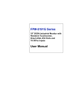
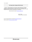
FPT-1015
User Manual
FPT-1015 User Manual
December 2006
372051A-01
Support
Worldwide Technical Support and Product Information
ni.com
National Instruments Corporate Headquarters
11500 North Mopac Expressway
Austin, Texas 78759-3504
USA Tel: 512 683 0100
Worldwide Offices
Australia 1800 300 800, Austria 43 0 662 45 79 90 0, Belgium 32 0 2 757 00 20, Brazil 55 11 3262 3599,
Canada 800 433 3488, China 86 21 6555 7838, Czech Republic 420 224 235 774, Denmark 45 45 76 26 00,
Finland 385 0 9 725 725 11, France 33 0 1 48 14 24 24, Germany 49 0 89 741 31 30, India 91 80 41190000,
Israel 972 0 3 6393737, Italy 39 02 413091, Japan 81 3 5472 2970, Korea 82 02 3451 3400,
Lebanon 961 0 1 33 28 28, Malaysia 1800 887710, Mexico 01 800 010 0793, Netherlands 31 0 348 433 466,
New Zealand 0800 553 322, Norway 47 0 66 90 76 60, Poland 48 22 3390150, Portugal 351 210 311 210,
Russia 7 495 783 68 51, Singapore 1800 226 5886, Slovenia 386 3 425 42 00, South Africa 27 0 11 805 8197,
Spain 34 91 640 0085, Sweden 46 0 8 587 895 00, Switzerland 41 56 200 51 51, Taiwan 886 02 2377 2222,
Thailand 662 278 6777, Turkey 90 212 279 3031, United Kingdom 44 0 1635 523545
For further support information, refer to the Technical Support and Professional Services appendix. To comment
on National Instruments documentation, refer to the National Instruments Web site at ni.com/info and enter
the info code feedback.
© 2006 National Instruments Corporation. All rights reserved.
Important Information
Warranty
The FPT-1015 is warranted against defects in materials and workmanship for a period of one year from the date of shipment, as evidenced by
receipts or other documentation. National Instruments will, at its option, repair or replace equipment that proves to be defective during the
warranty period. This warranty includes parts and labor.
The media on which you receive National Instruments software are warranted not to fail to execute programming instructions, due to defects in
materials and workmanship, for a period of 90 days from date of shipment, as evidenced by receipts or other documentation. National Instruments
will, at its option, repair or replace software media that do not execute programming instructions if National Instruments receives notice of such defects
during the warranty period. National Instruments does not warrant that the operation of the software shall be uninterrupted or error free.
A Return Material Authorization (RMA) number must be obtained from the factory and clearly marked on the outside of the package before any
equipment will be accepted for warranty work. National Instruments will pay the shipping costs of returning to the owner parts which are covered by
warranty.
National Instruments believes that the information in this document is accurate. The document has been carefully reviewed for technical accuracy. In
the event that technical or typographical errors exist, National Instruments reserves the right to make changes to subsequent editions of this document
without prior notice to holders of this edition. The reader should consult National Instruments if errors are suspected. In no event shall National
Instruments be liable for any damages arising out of or related to this document or the information contained in it.
EXCEPT AS SPECIFIED HEREIN, NATIONAL INSTRUMENTS MAKES NO WARRANTIES, EXPRESS OR IMPLIED, AND SPECIFICALLY DISCLAIMS ANY WARRANTY OF
MERCHANTABILITY OR FITNESS FOR A PARTICULAR PURPOSE. CUSTOMER’S RIGHT TO RECOVER DAMAGES CAUSED BY FAULT OR NEGLIGENCE ON THE PART OF NATIONAL
INSTRUMENTS SHALL BE LIMITED TO THE AMOUNT THERETOFORE PAID BY THE CUSTOMER. NATIONAL INSTRUMENTS WILL NOT BE LIABLE FOR DAMAGES RESULTING
FROM LOSS OF DATA, PROFITS, USE OF PRODUCTS, OR INCIDENTAL OR CONSEQUENTIAL DAMAGES, EVEN IF ADVISED OF THE POSSIBILITY THEREOF. This limitation of
the liability of National Instruments will apply regardless of the form of action, whether in contract or tort, including negligence. Any action against
National Instruments must be brought within one year after the cause of action accrues. National Instruments shall not be liable for any delay in
performance due to causes beyond its reasonable control. The warranty provided herein does not cover damages, defects, malfunctions, or service
failures caused by owner’s failure to follow the National Instruments installation, operation, or maintenance instructions; owner’s modification of the
product; owner’s abuse, misuse, or negligent acts; and power failure or surges, fire, flood, accident, actions of third parties, or other events outside
reasonable control.
Copyright
Under the copyright laws, this publication may not be reproduced or transmitted in any form, electronic or mechanical, including photocopying,
recording, storing in an information retrieval system, or translating, in whole or in part, without the prior written consent of National
Instruments Corporation.
National Instruments respects the intellectual property of others, and we ask our users to do the same. NI software is protected by copyright and other
intellectual property laws. Where NI software may be used to reproduce software or other materials belonging to others, you may use NI software only
to reproduce materials that you may reproduce in accordance with the terms of any applicable license or other legal restriction.
Trademarks
National Instruments, NI, ni.com, and LabVIEW are trademarks of National Instruments Corporation. Refer to the Terms of Use section
on ni.com/legal for more information about National Instruments trademarks.
Other product and company names mentioned herein are trademarks or trade names of their respective companies.
Members of the National Instruments Alliance Partner Program are business entities independent from National Instruments and have no agency,
partnership, or joint-venture relationship with National Instruments.
Patents
For patents covering National Instruments products, refer to the appropriate location: Help»Patents in your software, the patents.txt file
on your CD, or ni.com/patents.
WARNING REGARDING USE OF NATIONAL INSTRUMENTS PRODUCTS
(1) NATIONAL INSTRUMENTS PRODUCTS ARE NOT DESIGNED WITH COMPONENTS AND TESTING FOR A LEVEL OF
RELIABILITY SUITABLE FOR USE IN OR IN CONNECTION WITH SURGICAL IMPLANTS OR AS CRITICAL COMPONENTS IN
ANY LIFE SUPPORT SYSTEMS WHOSE FAILURE TO PERFORM CAN REASONABLY BE EXPECTED TO CAUSE SIGNIFICANT
INJURY TO A HUMAN.
(2) IN ANY APPLICATION, INCLUDING THE ABOVE, RELIABILITY OF OPERATION OF THE SOFTWARE PRODUCTS CAN BE
IMPAIRED BY ADVERSE FACTORS, INCLUDING BUT NOT LIMITED TO FLUCTUATIONS IN ELECTRICAL POWER SUPPLY,
COMPUTER HARDWARE MALFUNCTIONS, COMPUTER OPERATING SYSTEM SOFTWARE FITNESS, FITNESS OF COMPILERS
AND DEVELOPMENT SOFTWARE USED TO DEVELOP AN APPLICATION, INSTALLATION ERRORS, SOFTWARE AND HARDWARE
COMPATIBILITY PROBLEMS, MALFUNCTIONS OR FAILURES OF ELECTRONIC MONITORING OR CONTROL DEVICES,
TRANSIENT FAILURES OF ELECTRONIC SYSTEMS (HARDWARE AND/OR SOFTWARE), UNANTICIPATED USES OR MISUSES, OR
ERRORS ON THE PART OF THE USER OR APPLICATIONS DESIGNER (ADVERSE FACTORS SUCH AS THESE ARE HEREAFTER
COLLECTIVELY TERMED “SYSTEM FAILURES”). ANY APPLICATION WHERE A SYSTEM FAILURE WOULD CREATE A RISK OF
HARM TO PROPERTY OR PERSONS (INCLUDING THE RISK OF BODILY INJURY AND DEATH) SHOULD NOT BE RELIANT SOLELY
UPON ONE FORM OF ELECTRONIC SYSTEM DUE TO THE RISK OF SYSTEM FAILURE. TO AVOID DAMAGE, INJURY, OR DEATH,
THE USER OR APPLICATION DESIGNER MUST TAKE REASONABLY PRUDENT STEPS TO PROTECT AGAINST SYSTEM FAILURES,
INCLUDING BUT NOT LIMITED TO BACK-UP OR SHUT DOWN MECHANISMS. BECAUSE EACH END-USER SYSTEM IS
CUSTOMIZED AND DIFFERS FROM NATIONAL INSTRUMENTS' TESTING PLATFORMS AND BECAUSE A USER OR APPLICATION
DESIGNER MAY USE NATIONAL INSTRUMENTS PRODUCTS IN COMBINATION WITH OTHER PRODUCTS IN A MANNER NOT
EVALUATED OR CONTEMPLATED BY NATIONAL INSTRUMENTS, THE USER OR APPLICATION DESIGNER IS ULTIMATELY
RESPONSIBLE FOR VERIFYING AND VALIDATING THE SUITABILITY OF NATIONAL INSTRUMENTS PRODUCTS WHENEVER
NATIONAL INSTRUMENTS PRODUCTS ARE INCORPORATED IN A SYSTEM OR APPLICATION, INCLUDING, WITHOUT
LIMITATION, THE APPROPRIATE DESIGN, PROCESS AND SAFETY LEVEL OF SUCH SYSTEM OR APPLICATION.
Compliance
Compliance with FCC/Canada Radio Frequency Interference
Regulations
Determining FCC Class
The Federal Communications Commission (FCC) has rules to protect wireless communications from interference. The FCC
places digital electronics into two classes. These classes are known as Class A (for use in industrial-commercial locations only)
or Class B (for use in residential or commercial locations). All National Instruments (NI) products are FCC Class A products.
Depending on where it is operated, this Class A product could be subject to restrictions in the FCC rules. (In Canada, the
Department of Communications (DOC), of Industry Canada, regulates wireless interference in much the same way.) Digital
electronics emit weak signals during normal operation that can affect radio, television, or other wireless products.
All Class A products display a simple warning statement of one paragraph in length regarding interference and undesired
operation. The FCC rules have restrictions regarding the locations where FCC Class A products can be operated.
Consult the FCC Web site at www.fcc.gov for more information.
FCC/DOC Warnings
This equipment generates and uses radio frequency energy and, if not installed and used in strict accordance with the instructions
in this manual and the CE marking Declaration of Conformity*, may cause interference to radio and television reception.
Classification requirements are the same for the Federal Communications Commission (FCC) and the Canadian Department
of Communications (DOC).
Changes or modifications not expressly approved by NI could void the user’s authority to operate the equipment under the
FCC Rules.
Class A
Federal Communications Commission
This equipment has been tested and found to comply with the limits for a Class A digital device, pursuant to part 15 of the FCC
Rules. These limits are designed to provide reasonable protection against harmful interference when the equipment is operated
in a commercial environment. This equipment generates, uses, and can radiate radio frequency energy and, if not installed and
used in accordance with the instruction manual, may cause harmful interference to radio communications. Operation of this
equipment in a residential area is likely to cause harmful interference in which case the user is required to correct the interference
at their own expense.
Canadian Department of Communications
This Class A digital apparatus meets all requirements of the Canadian Interference-Causing Equipment Regulations.
Cet appareil numérique de la classe A respecte toutes les exigences du Règlement sur le matériel brouilleur du Canada.
Compliance with EU Directives
Users in the European Union (EU) should refer to the Declaration of Conformity (DoC) for information* pertaining to the
CE marking. Refer to the Declaration of Conformity (DoC) for this product for any additional regulatory compliance
information. To obtain the DoC for this product, visit ni.com/certification, search by model number or product line,
and click the appropriate link in the Certification column.
* The CE marking Declaration of Conformity contains important supplementary information and instructions for the user or
installer.
Conventions
The following conventions are used in this manual:
»
The » symbol leads you through nested menu items and dialog box options
to a final action. The sequence File»Page Setup»Options directs you to
pull down the File menu, select the Page Setup item, and select Options
from the last dialog box.
This icon denotes a note, which alerts you to important information.
This icon denotes a caution, which advises you of precautions to take to
avoid injury, data loss, or a system crash. When this symbol is marked on a
product, refer to the Safety section of Appendix A, Specifications, for
information about precautions to take.
When symbol is marked on a product, it denotes a warning advising you to
take precautions to avoid electrical shock.
When symbol is marked on a product, it denotes a component that may be
hot. Touching this component may result in bodily injury.
bold
Bold text denotes items that you must select or click in the software, such
as menu items and dialog box options. Bold text also denotes parameter
names.
italic
Italic text denotes variables, emphasis, a cross-reference, or an introduction
to a key concept. Italic text also denotes text that is a placeholder for a word
or value that you must supply.
monospace
Text in this font denotes text or characters that you should enter from the
keyboard, sections of code, programming examples, and syntax examples.
This font is also used for the proper names of disk drives, paths, directories,
programs, subprograms, subroutines, device names, functions, operations,
variables, filenames, and extensions.
monospace bold
Bold text in this font denotes the messages and responses that the computer
automatically prints to the screen. This font also emphasizes lines of code
that are different from the other examples.
Contents
Chapter 1
General Information
Introduction....................................................................................................................1-1
Connectors .....................................................................................................................1-1
VGA Port (DB15)............................................................................................1-1
USB Type B Touchscreen Connector .............................................................1-2
DC 12 V Power In ...........................................................................................1-2
Chapter 2
Mounting
Important Safety Information ........................................................................................2-1
Wall Mounting ...............................................................................................................2-3
Panel Mounting..............................................................................................................2-4
Rack Mounting ..............................................................................................................2-5
Desktop Stand Mounting ...............................................................................................2-6
Power Adapter Mounting...............................................................................................2-6
Appendix A
Specifications
Appendix B
Display Timing Mode and OSD
Appendix C
Touchscreen
Appendix D
Technical Support and Professional Services
Index
© National Instruments Corporation
vii
FPT-1015 User Manual
1
General Information
This chapter includes an overview of the FPT-1015 human machine
interface (HMI).
Introduction
The FPT-1015 is a 15 in. color TFT LCD flat panel monitor for industrial
applications. With the optional touchscreen, this monitor is a user-friendly
system control interface and can be easily transformed into a remote
control system.
In addition to its usual application as an LCD panel monitor, the FPT-1015
includes a Direct VGA control signal input, making it compatible with
industrial PCs and workstations.
The onscreen display (OSD) function allows you to adjust the display and
turn the backlight on and off.
The chassis is made of durable steel. The front panel is made of Al-Mg with
NEMA4/IP65 compliance.
Connectors
The FPT-1015 includes the following connectors.
VGA Port (DB15)
You can connect the FPT-1015 to a system via the external 15-pin DB-15
connector.
Note Before connecting a VGA cable between the FPT-1015 and a PC, be sure the vertical
frequency is within the acceptable range if you have installed an operating system on the
PC. If you have not installed an operating system, adjust the vertical frequency to fall
within the range.
© National Instruments Corporation
1-1
FPT-1015 User Manual
Chapter 1
General Information
USB Type B Touchscreen Connector
The FPT-1015 includes this connector and a touchscreen cable if a
touchscreen is installed. You must connect it to the PC USB port.
DC 12 V Power In
This connector connects to the DC 12 V switching power supply.
FPT-1015 User Manual
1-2
ni.com
2
Mounting
This chapter explains how to mount the FPT-1015.
Important Safety Information
Before setting up the FPT-1015, read these safety instructions carefully.
Disconnect this equipment from any AC outlet before cleaning. Use a damp
cloth. Do not use liquid or spray detergents for cleaning.
For plug-in equipment, the power outlet socket must be located near the
equipment and must be easily accessible.
Keep this equipment away from excessive humidity.
Place this equipment on a reliable surface during installation. Dropping it
or letting it fall may cause damage.
The openings on the enclosure are for air convection. Protect the equipment
from overheating. Do not cover the openings.
Make sure the power source voltage is correct before connecting the
equipment to the power outlet.
Position the power cord so that it cannot be stepped on. Do not place
anything over the power cord.
All cautions and warnings on the equipment should be noted.
If the equipment is not to be used for a long time, disconnect it from the
power source to avoid damage by transient overvoltage.
Never pour any liquid into an opening. This may cause fire or electrical
shock.
Never open the equipment. For safety reasons, only qualified service
personnel should open the equipment.
© National Instruments Corporation
2-1
FPT-1015 User Manual
Chapter 2
Mounting
If one of the following situations arises, have service personnel check the
equipment:
•
The power cord or plug is damaged.
•
Liquid has penetrated into the equipment.
•
The equipment has been exposed to moisture.
•
The equipment does not work well, or you cannot get it to work
according to the user manual.
•
The equipment has been dropped and damaged.
•
The equipment has obvious signs of breakage.
Do not leave this equipment in an environment where the storage
temperature may go below –20 °C (–4 °F) or above 60 °C (140 °F). Doing
so could damage the equipment. The equipment should be in a controlled
environment.
There is a danger of explosion if the battery is incorrectly replaced. Replace the
battery only with the same or equivalent type recommended by the manufacturer. Discard
used batteries according to the manufacturer’s instructions.
Caution
The sound pressure level at the operator’s position according to
IEC 704-1:1982 is no more than 70 dB (A).
FPT-1015 User Manual
2-2
ni.com
Chapter 2
Mounting
Wall Mounting
The FPT-1015 wall mounting kit is optional. As shown in Figure 2-1,
screw the hook and wall-mounted brackets to the wall and attach the
FPT-1015 to the bracket.
Hook Bracket
Wall-Mounting Bracket
Figure 2-1. Wall Mounting
© National Instruments Corporation
2-3
FPT-1015 User Manual
Chapter 2
Mounting
Panel Mounting
Refer to Figure 2-2 and follow these steps to install the FPT-1015 in a
panel:
1.
Place the panel-mounting brackets on the FPT-1015.
2.
Fasten the panel-mounting brackets with the screws.
3.
Insert the FPT-1015 in the panel.
4.
Tighten the screws to fasten the FPT-1015 to the panel.
Figure 2-2. Panel Mounting
FPT-1015 User Manual
2-4
ni.com
Chapter 2
Mounting
Rack Mounting
The rack mounting kit is optional. As shown in Figure 2-3, you can
directly mount the FPT-1015 in a standard 19 in. rack and secure it
with four screws.
Figure 2-3. Rack Mounting
© National Instruments Corporation
2-5
FPT-1015 User Manual
Chapter 2
Mounting
Desktop Stand Mounting
The desktop stand kit is optional. As shown in Figure 2-4, attach the
desktop stand bracket to the rear of the monitor with two screws.
Figure 2-4. Desktop Stand Mounting
Power Adapter Mounting
Attach the power adapter bracket to the rear of the FPT-1015 monitor using
four screws.
Figure 2-5. Power Adapter Mounting
FPT-1015 User Manual
2-6
ni.com
A
Specifications
Physical
Construction ........................................... Heavy-duty steel chassis
Front Panel ............................................. Al-Mg, NEMA4/IP65 compliant
Control ................................................... Onscreen display (OSD) control
pad on front side
Mounting................................................ Panel, wallmount, rackmount
(with rackmount kit), desktop, or
VESA arm
Cutout dimension ................................... 373.5 × 297.5 mm
(14.7 in. × 11.71 in.)
Weight .................................................... 4.5 kg (9.9 lb)
Vibration (operating).............................. 5 to 17 Hz, double-amplitude
displacement; 17 to 500 Hz,
1.0 G peak to peak
Power consumption................................ +12 V +/– 10% @ 2.5 A
© National Instruments Corporation
A-1
FPT-1015 User Manual
Appendix A
Specifications
Dimensions
383
[15.07]
270.59 308.26 372.6
[10.65] [12.13] [14.66]
307 [12.08]
4.5
18.5 48.13
[0.17] [0.72] [1.89]
214.1 [8.42]
15 [0.59]
296.6 [11.67]
100 [3.93]
75 [2.95]
75
100
[2.95] [3.93]
FPT-1015 User Manual
A-2
ni.com
Appendix A
Specifications
Touchscreen
Type ....................................................... 8 wire, analog resistive
Resolution .............................................. 1024 × 1024
Light transmission.................................. 75% (gouge hardness is greater
than 4 H per ASTM D3363-92 for
HCC01, HCG10, and HCG12)
Controller ............................................... RS232 interface or USB 1.1
OS support.............................................. Windows 9x/NT/2000/XP/
CE 4.2, MS-DOS
Lifespan.................................................. 1 million activations (typical)
at a single point with a 5/8 in.
diameter silicone finger with a
350 g load at 2 touches per second
Contact bounce....................................... <10 ms
Operating voltage ................................... 5 V (typical)
Sheet resistance ...................................... 350 +/– 22% Ω per square
Linearity ................................................. <1.5% full-scale linearity error in
either direction
Insulation resistance............................... >20 MΩ @ 25 VDC
Test conditions ....................................... 4 H hardness, 0.04 in. stylus pen,
350 g load
Character activation life ......................... >100,000 characters written
within a 20 × 20 mm area on the
touchscreen
Chemical resistance................................ Hard coating is highly resistant to
most solvents and chemicals
Visible light transmission....................... 75% typical (>74% @ 550 nm
test)
Clarity..................................................... Clear finish—25%;
antiglare finish—15%
© National Instruments Corporation
A-3
FPT-1015 User Manual
Appendix A
Specifications
Sensor board ...........................................Chemical strengthened glass
with 4 H hardness standard (test
condition: ASTM D3363-92A)
Ball drop test...........................................Able to bear a 225 g steel ball
dropped from 660 mm elevation
without breaking
Accelerated aging ...................................100 h at 60 °C/95% relative
humidity
Thermal shock ........................................25 cycles (one cycle is 30 min.
dwell alternating from –40 to
85 °C with less than 10 min.
transfer time
LCD
Display type ............................................XGA TFT- LCD
Display size.............................................15 in.
Maximum colors.....................................262,000
Maximum resolution...............................1024 × 768
Viewing angle.........................................140° (H), 120° (V)
Luminance ..............................................250 cd/m2
Contrast ratio ..........................................500:1 (typical)
Lamp lifetime (MTBF) ...........................40,000 h
Power Adapter
Maximum output power .........................42 W
AC input voltage.....................................100 to 240 VAC, 50–60 Hz
Output voltage ........................................+12 V @ 3.5 A
FPT-1015 User Manual
A-4
ni.com
Appendix A
Specifications
Environmental
Maximum altitude .................................. 2,000 m
Pollution Degree .................................... 2
Indoor use only
Touchscreen
Operating temperature range.................. –20 to 50 °C, 2 weeks at
50 °C/90% relative humidity
Storage temperature high ....................... 70 °C, 240 h at ambient humidity
Storage temperature low ........................ –40 °C, continuous at ambient
humidity
LCD
Operating temperature............................ 0 to 50 °C (32 to 122 °F)
Storage temperature ............................... –20 to 60 °C (–4 to 140 °F)
Safety
This product is designed to meet the requirements of the following
standards of safety for information technology equipment:
•
•
IEC 60950-1, EN 60950-1
UL 60950-1, CSA 60950-1
Note For UL and other safety certifications, refer to the product label or visit
ni.com/certification, search by model number or product line, and click the
appropriate link in the Certification column.
© National Instruments Corporation
A-5
FPT-1015 User Manual
Appendix A
Specifications
Electromagnetic Compatibility
This product is designed to meet the requirements of the following
standards of EMC for electrical equipment for measurement, control, and
laboratory use:
Note
•
EN 55024, CISPR 24 EMC requirements
•
EN 55022, CISPR 22 Emissions; Class A
•
EN 55011, CISPR 11 Emissions; Class A
•
CE, C-Tick, ICES, and FCC Part 15 Emissions; Class A
For EMC compliance, operate this device according to product documentation.
CE Compliance
This product meets the essential requirements of applicable European
Directives, as amended for CE marking, as follows:
•
•
73/23/EEC; Low-Voltage Directive (safety)
89/336/EEC; Electromagnetic Compatibility Directive (EMC)
Refer to the Declaration of Conformity (DoC) for this product for any additional
regulatory compliance information. To obtain the DoC for this product, visit ni.com/
certification, search by model number or product line, and click the appropriate link
in the Certification column.
Note
Waste Electrical and Electronic Equipment (WEEE)
At the end of their life cycle, all products must be sent to a WEEE recycling
center. For more information about WEEE recycling centers and National Instruments
WEEE initiatives, visit ni.com/environment/weee.htm.
EU Customers
Cleaning
If you need to clean the unit, use a soft, nonmetallic brush. Make sure that
the unit is completely dry and free from contaminants before returning it to
service.
FPT-1015 User Manual
A-6
ni.com
B
Display Timing Mode and OSD
Supported Input Timing Modes
The FPT-1015 supports and automatically recognizes the frequencies listed
in Table B-1.
Table B-1. Supported Input Formats
Vertical Frequencies
Resolution
56 Hz
60 Hz
70 Hz
72 Hz
75 Hz
640 × 480
—
Yes
—
Yes
Yes
720 × 400
—
—
Yes
—
—
800 × 600
Yes
Yes
—
Yes
Yes
1024 × 768
—
Yes
Yes
—
Yes
Even if you use the preset timing, you may need to adjust functions such as
horizontal period, CLK-delay, and display position. The adjusted values are memorized
in every preset number.
Note
© National Instruments Corporation
B-1
FPT-1015 User Manual
Appendix B
Display Timing Mode and OSD
Keypad Interface
Table B-2 lists key functions.
Table B-2. Key Functions
Key
Auto
Sel
Function
Executes the autoadjustment process.
Shows the OSD screen or selects an item to change its
setting.
Moves between items or increases/decreases item
settings.
Press both keys simultaneously to lock/unlock the
current settings.
Exit
On/Off
Closes the selected item or the entire OSD screen.
Turns the FPT-1015 backlight on and off. When
power is off, the power indicator blinks.
Power Indicator LED Status
The keypad interface includes a dual-color LED driver to indicate status as
follows:
FPT-1015 User Manual
•
Green—The board detects an input signal and sends an output signal
to the LCD panel.
•
Orange—No signal detected, or out of range.
•
Green and blinking—The backlight is off.
•
No color—Power is off.
B-2
ni.com
Appendix B
Display Timing Mode and OSD
OSD Function
Each selected OSD function value is stored into LCD memory after an SEL
signal input or timeout. The stored values are not affected if the power is
off. However, the selected value is not available if a selected mode is
changed or power is turned off before timeout.
Table B-3 lists the OSD function menus.
Table B-3. OSD Function Menus
Main Menu
Submenu
Brightness
—
Contrast
Contrast
Color
9300k
6500k
Functionality
Adjust the display
brightness
Adjust RGB channel
contrast simultaneously
Adjust selected RGB
channel color
User
Position
© National Instruments Corporation
H.Position
Move the input image
capture window left or
right
V.Position
Move the input image
capture window up or
down
Phase
Adjust the ADC sample
clock phase
Clock
Adjust the number of
clocks per line
All Reset
All Reset
Information
—
B-3
Reset menu parameters to
factory default settings
System input mode
information and
maximum range the
screen supports
FPT-1015 User Manual
C
Touchscreen
This appendix explains how to install and configure the FPT-1015
touchscreen.
Introduction
The FPT-1015 touchscreen uses advanced 8-wire resistive technology,
providing more accurate sensing capacity than other technologies. The
touchscreen is specially designed for tough industrial environments.
Installing the Driver for Windows
The touchscreen driver is on the driver CD included with the FPT-1015.
To install the driver, locate the Windows Driver V4.1.1008 folder. Run
setup.exe in that folder and follow the installation instructions.
Configuring the Touchscreen
After you install the touchscreen driver, the FPT-1015 automatically finds
the new touchscreen controller board on rebooting. The touchscreen is
connected, but not calibrated. Follow these steps to start calibration:
1.
After installation and rebooting, click the PenMount Monitor pm icon
in the menu bar and select Control Panel.
2.
When the PenMount Control Panel appears, click Calibrate.
PenMount Control Panel
The PenMount Control Panel functions are Calibrate, Multiple Monitors,
Setting, PenMount Rotating Functions, Tools, and About.
Calibrate
The Calibrate function includes two ways to calibrate your touchscreen.
Standard calibration adjusts most touchscreens. Advanced calibration
adjusts aging touchscreens.
© National Instruments Corporation
C-1
FPT-1015 User Manual
Appendix C
Touchscreen
Standard Calibration
When you click this button, arrows
appear pointing to red squares. Use your
finger or stylus to touch the red squares in
sequence. After you touch the fifth red
square, calibration is complete. To skip,
press <Esc>.
Note To access the Advanced Calibration option, go to the Tools tab and select Advanced
Calibration.
Advanced Calibration
Advanced calibration uses 4, 9, 16, or
25 points to effectively calibrate the
linearity of aged touchscreens. Click
this button and touch the red squares in
sequence with a stylus. To skip, press
<Esc>.
Note The older the touchscreen, the more advanced calibration points you need for
accurate calibration. Use a stylus during advanced calibration for greater accuracy.
Plot Calibration Data
When you select this function, a touch
panel linearity comparison graph appears
after you finish advanced calibration.
The blue lines show linearity before
calibration, and black lines show linearity
after calibration.
Multiple Monitors
The Multiple Monitors function supports two to six touchscreen displays
for one system. Each monitor requires its own PenMount touchscreen
control board, installed inside the display or in a central unit. You must
connect the control boards to the computer COM ports via the RS232
interface. Driver installation procedures are the same as for a single
monitor. Multiple Monitors supports the following modes:
•
Windows Extend Monitor function
•
Matrox DualHead multiscreen function
•
nVidia nView function
The Multiple Monitors function is for multiple displays only. Do not use this
function with only one touchscreen display.
Note
FPT-1015 User Manual
C-2
ni.com
Appendix C
Touchscreen
Follow these steps to enable multiple displays:
1.
In the Multiple Monitors tab, check the Multiple Monitor Support
box.
2.
Click Map Touch Screens to assign touch controllers to the displays.
3.
When the mapping screen message appears, click OK.
4.
Touch each screen as it displays Please touch this monitor.
Following this sequence and touching each screen is called mapping
the touchscreens.
5.
Touching all screens completes the mapping, and the desktop
reappears on the monitors.
6.
Select a display and execute the Calibration function. A message to
start calibration appears. Click OK.
7.
Touch this screen to start its calibration appears on
one of the screens. Touch the screen.
8.
Touch the red square messages appear. Touch the red squares in
sequence.
9.
Continue calibration for each monitor by clicking Standard
Calibration and touching the red squares.
If you use a single VGA output for multiple monitors, do not use the Multiple
Monitors function. Follow the regular procedure for calibrating each monitor.
Note
The rotating function is disabled if you use the Multiple Monitors function.
If you change the display resolution or screen address, you must map the touchscreens
again so the system understands where the displays are.
Setting
Use this tab to change the configuration for specific touchscreen
applications, such as point-of-sales (POS) terminals, beep settings,
stabilizing cursor, and automatic station detection.
Touch Mode
Allows the enabling and disabling of the
mouse’s ability to drag onscreen icons.
Mouse Emulation—This option allows
the mouse to function normally and drag
icons.
© National Instruments Corporation
C-3
FPT-1015 User Manual
Appendix C
Touchscreen
Click on Touch—This option allows the
mouse to have only a click function, and
dragging is disabled.
Beep Sound Mode
Enable Beep Sound—This option turns
the beep function on and off.
Beep on Pen Down—In this mode, the
beep occurs when the pen goes down.
Beep on Pen Up—In this mode, the beep
occurs when the pen goes up.
Kind of Sound—This option modifies the
type of sound the beep makes.
Beep on Both—In this mode, the beep
occurs when the pen goes down and up.
Beep Frequency—This option modifies
the sound frequency.
Beep Duration—This option modifies the
sound duration.
Cursor Stabilizer
Select this option to reduce cursor
vibration, or where there maybe be excess
vibration. Normally, you should not
select this option.
PenMount Rotating Functions
The PenMount driver for Windows supports several display rotation
software packages, such as:
FPT-1015 User Manual
•
Portrait Pivot screen rotation software
•
The ATI display driver rotate function
•
The nVidia display driver rotate function
•
The SMI display driver rotate function
•
The Intel 845G/GE display driver rotate function
C-4
ni.com
Appendix C
Touchscreen
Configuring the Rotate Function
Follow these steps to configure the rotate function:
Note
1.
Install the rotation software package.
2.
Choose the rotate function in the software. The calibration screen
appears automatically. Touch the point, and rotation is mapped.
The rotate function is disabled if you use monitor mapping.
Tools
Draw
This option tests the touchscreen
operation. The display shows touch
location. Click Draw to start. When you
touch the screen with your finger or a
stylus, the drawing screen registers touch
activity such as left, right, up, down, pen
up, and pen down.
Click Clear Screen to clear the drawing.
Advanced Calibration
This option enables or disables the
Advanced Calibration Mode on the
Calibration tab.
Right Button Icon
This option shows or hides the icon for
switching buttons and lets you select
whether the icon is in the System Tray
or on the desktop.
Right Button Emulation
This option enables or disables right
button emulation.
About
The About panel displays information about the PenMount controller and
driver version.
© National Instruments Corporation
C-5
FPT-1015 User Manual
Appendix C
Touchscreen
PenMount Monitor Menu Icon
The PenMount Monitor icon (pm) appears in the Windows menu bar when
you turn on PenMount Monitor in PenMount USB Utilities.
PenMount Monitor has the following functions:
FPT-1015 User Manual
Control Panel
Brings up the PenMount Control Panel.
Beep
Turns the beep on or off.
Right Button
When you select this function, a mouse
icon appears. Click this icon to switch
between right and left button functions.
Exit
Exits the PenMount Monitor function.
C-6
ni.com
Technical Support and
Professional Services
D
Visit the following sections of the National Instruments Web site at
ni.com for technical support and professional services:
•
Support—Online technical support resources at ni.com/support
include the following:
–
Self-Help Resources—For answers and solutions, visit the
award-winning National Instruments Web site for software drivers
and updates, a searchable KnowledgeBase, product manuals,
step-by-step troubleshooting wizards, thousands of example
programs, tutorials, application notes, instrument drivers, and
so on.
–
Free Technical Support—All registered users receive free Basic
Service, which includes access to hundreds of Application
Engineers worldwide in the NI Discussion Forums at
ni.com/forums. National Instruments Application Engineers
make sure every question receives an answer.
For information about other technical support options in your
area, visit ni.com/services or contact your local office at
ni.com/contact.
•
Training and Certification—Visit ni.com/training for
self-paced training, eLearning virtual classrooms, interactive CDs,
and Certification program information. You also can register for
instructor-led, hands-on courses at locations around the world.
•
System Integration—If you have time constraints, limited in-house
technical resources, or other project challenges, National Instruments
Alliance Partner members can help. To learn more, call your local
NI office or visit ni.com/alliance.
If you searched ni.com and could not find the answers you need, contact
your local office or NI corporate headquarters. Phone numbers for our
worldwide offices are listed at the front of this manual. You also can visit
the Worldwide Offices section of ni.com/niglobal to access the branch
office Web sites, which provide up-to-date contact information, support
phone numbers, email addresses, and current events.
© National Instruments Corporation
D-1
FPT-1015 User Manual
Index
A
E
About function, C-5
advanced calibration, C-2
electromagnetic compatibility
specifications, A-6
environmental specifications, A-5
LCD, A-5
touchscreen, A-5
examples (NI resources), D-1
C
Calibrate function, C-1
calibration
advanced, C-2
plot calibration data, C-2
standard, C-2
CE compliance specifications, A-6
cleaning, A-6
connectors, 1-1
DC 12 V power in, 1-2
USB type B touchscreen connector, 1-2
VGA port (DB15), 1-1
conventions used in the manual, v
F
FPT-1015, B-1
CE compliance specifications, A-6
cleaning specifications, A-6
connectors, 1-1
DC 12 V power in, 1-2
USB type B touchscreen
connector, 1-2
VGA port (DB15), 1-1
dimensions, A-2
electromagnetic compatibility
specifications, A-6
environmental specifications, A-5
LCD, A-5
touchscreen, A-5
introduction, 1-1
keypad
functions (table), B-2
interface, B-2
LCD specifications, A-4
D
DC 12 V power in, 1-2
desktop stand mounting, 2-6
diagnostic tools (NI resources), D-1
dimensions, A-2
display timing mode, B-1
documentation
conventions used in the manual, v
NI resources, D-1
drivers (NI resources), D-1
© National Instruments Corporation
I-1
FPT-1015 User Manual
Index
K
mounting, 2-1
desktop stand mounting, 2-6
panel mounting, 2-4
power adapter mounting, 2-6
rack mounting, 2-5
wall mounting, 2-3
OSD
function, B-3
menus (table), B-3
PenMount Monitor menu icon, C-6
PenMount rotating functions, C-4
configuring, C-5
physical specifications, A-1
power adapter specifications, A-4
power indicator LED status, B-2
safety
information, 2-1
specifications, A-5
specifications, A-1
supported input formats (table), B-1
supported input timing modes, B-1
touchscreen, C-1
configuring, C-1
installing driver for Windows, C-1
introduction, C-1
PenMount Control Panel, C-1
specifications, A-3
Waste Electrical and Electronic
Equipment specifications, A-6
keypad
functions (table), B-2
interface, B-2
KnowledgeBase, D-1
L
LCD specifications, A-4
environmental, A-5
M
mounting, 2-1
desktop stand mounting, 2-6
panel mounting, 2-4
power adapter mounting, 2-6
rack mounting, 2-5
wall mounting, 2-3
Multiple Monitors function, C-2
N
National Instruments support and
services, D-1
O
OSD, B-1
function, B-3
menus (table), B-3
H
help
P
technical support, D-1
panel mounting, 2-4
PenMount Control Panel, C-1
About function, C-5
Calibrate function, C-1
Multiple Monitors function, C-2
Setting function, C-3
Tools function, C-5
I
instrument drivers (NI resources), D-1
introduction, 1-1
FPT-1015 User Manual
I-2
ni.com
Index
supported input formats (table), B-1
supported input timing modes, B-1
PenMount Monitor menu icon, C-6
PenMount rotating functions, C-4
configuring, C-5
physical specifications, A-1
plot calibration data, C-2
power adapter
mounting, 2-6
specifications, A-4
power indicator LED status, B-2
programming examples (NI resources), D-1
T
technical support, D-1
Tools function, C-5
touchscreen, C-1
configuring, C-1
environmental specifications, A-5
installing driver for Windows, C-1
introduction, C-1
PenMount Control Panel, C-1
About function, C-5
Calibrate function, C-1
Multiple Monitors function, C-2
Setting function, C-3
Tools function, C-5
PenMount Monitor menu icon, C-6
PenMount rotating functions, C-4
configuring, C-5
specifications, A-3
training and certification (NI resources), D-1
troubleshooting (NI resources), D-1
R
rack mounting, 2-5
rotating functions, C-4
configuring, C-5
S
safety
information, 2-1
specifications, A-5
Setting function, C-3
software (NI resources), D-1
specifications, A-1
CE compliance, A-6
cleaning, A-6
dimensions, A-2
electromagnetic compatibility, A-6
environmental, A-5
LCD, A-5
touchscreen, A-5
LCD, A-4
physical, A-1
power adapter, A-4
safety, A-5
touchscreen, A-3
Waste Electrical and Electronic
Equipment compliance, A-6
standard calibration, C-2
support, technical, D-1
© National Instruments Corporation
U
USB type B touchscreen connector, 1-2
V
VGA port (DB15), 1-1
W
wall mounting, 2-3
Waste Electrical and Electronic Equipment
compliance specifications, A-6
Web resources, D-1
I-3
FPT-1015 User Manual