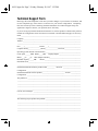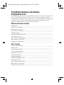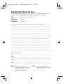
1
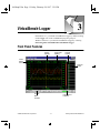
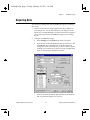
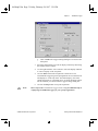
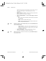
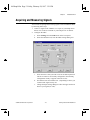
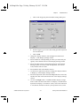
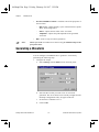
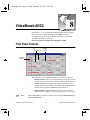
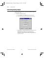
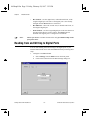
01Title.fm Page 1 Friday, February 28, 1997 3:19 PM
Getting Started
with
VirtualBench™
Getting Started with VirtualBench
March 1997 Edition
Part Number 321518A-01
© Copyright 1997 National Instruments Corporation. All rights reserved.
01Title.fm Page 2 Friday, February 28, 1997 3:19 PM
Internet Support
[email protected]
E-mail: [email protected]
FTP Site: ftp.natinst.com
Web Address: http://www.natinst.com
Bulletin Board Support
BBS United States: (512) 794-5422
BBS United Kingdom: 01635 551422
BBS France: 01 48 65 15 59
Fax-on-Demand Support
(512) 418-1111
Telephone Support (U.S.)
Tel: (512) 795-8248
Fax: (512) 794-5678
International Offices
Australia 02 9874 4100, Austria 0662 45 79 90 0, Belgium 02 757 00 20,
Canada (Ontario) 905 785 0085, Canada (Québec) 514 694 8521, Denmark 45 76 26 00,
Finland 09 527 2321, France 01 48 14 24 24, Germany 089 741 31 30, Hong Kong 2645 3186,
Israel 03 5734815, Italy 02 413091, Japan 03 5472 2970, Korea 02 596 7456,
Mexico 5 520 2635, Netherlands 0348 433466, Norway 32 84 84 00, Singapore 2265886,
Spain 91 640 0085, Sweden 08 730 49 70, Switzerland 056 200 51 51, Taiwan 02 377 1200,
U.K. 01635 523545
National Instruments Corporate Headquarters
6504 Bridge Point Parkway
Austin, TX 78730-5039
Tel: (512) 794-0100
02Warr.fm Page 3 Friday, February 28, 1997 3:19 PM
Important Information
Warranty
The media on which you receive National Instruments software are warranted not to fail to execute programming
instructions, due to defects in materials and workmanship, for a period of 90 days from date of shipment, as evidenced
by receipts or other documentation. National Instruments will, at its option, repair or replace software media that do
not execute programming instructions if National Instruments receives notice of such defects during the warranty
period. National Instruments does not warrant that the operation of the software shall be uninterrupted or error free.
A Return Material Authorization (RMA) number must be obtained from the factory and clearly marked on the outside
of the package before any equipment will be accepted for warranty work. National Instruments will pay the shipping
costs of returning to the owner parts which are covered by warranty.
National Instruments believes that the information in this manual is accurate. The document has been carefully
reviewed for technical accuracy. In the event that technical or typographical errors exist, National Instruments reserves
the right to make changes to subsequent editions of this document without prior notice to holders of this edition. The
reader should consult National Instruments if errors are suspected. In no event shall National Instruments be liable for
any damages arising out of or related to this document or the information contained in it.
EXCEPT AS SPECIFIED HEREIN, NATIONAL INSTRUMENTS MAKES NO WARRANTIES, EXPRESS OR IMPLIED, AND
SPECIFICALLY DISCLAIMS ANY WARRANTY OF MERCHANTABILITY OR FITNESS FOR A PARTICULAR PURPOSE.
CUSTOMER’S RIGHT TO RECOVER DAMAGES CAUSED BY FAULT OR NEGLIGENCE ON THE PART OF NATIONAL
INSTRUMENTS SHALL BE LIMITED TO THE AMOUNT THERETOFORE PAID BY THE CUSTOMER . NATIONAL INSTRUMENTS
WILL NOT BE LIABLE FOR DAMAGES RESULTING FROM LOSS OF DATA, PROFITS, USE OF PRODUCTS , OR INCIDENTAL OR
CONSEQUENTIAL DAMAGES , EVEN IF ADVISED OF THE POSSIBILITY THEREOF . This limitation of the liability of National
Instruments will apply regardless of the form of action, whether in contract or tort, including negligence. Any action
against National Instruments must be brought within one year after the cause of action accrues. National Instruments
shall not be liable for any delay in performance due to causes beyond its reasonable control. The warranty provided
herein does not cover damages, defects, malfunctions, or service failures caused by owner’s failure to follow the
National Instruments installation, operation, or maintenance instructions; owner’s modification of the product;
owner’s abuse, misuse, or negligent acts; and power failure or surges, fire, flood, accident, actions of third parties, or
other events outside reasonable control.
Copyright
Under the copyright laws, this publication may not be reproduced or transmitted in any form, electronic or mechanical,
including photocopying, recording, storing in an information retrieval system, or translating, in whole or in part,
without the prior written consent of National Instruments Corporation.
Trademarks
DAQCard™, natinst.com™, NI-DAQ™, SCXI™, and VirtualBench™ are trademarks of National Instruments
Corporation.
Product and company names listed are trademarks or trade names of their respective companies.
WARNING REGARDING MEDICAL AND CLINICAL USE OF NATIONAL INSTRUMENTS PRODUCTS
National Instruments products are not designed with components and testing intended to ensure a level of reliability
suitable for use in treatment and diagnosis of humans. Applications of National Instruments products involving
medical or clinical treatment can create a potential for accidental injury caused by product failure, or by errors on the
part of the user or application designer. Any use or application of National Instruments products for or involving
medical or clinical treatment must be performed by properly trained and qualified medical personnel, and all traditional
medical safeguards, equipment, and procedures that are appropriate in the particular situation to prevent serious injury
or death should always continue to be used when National Instruments products are being used. National Instruments
products are NOT intended to be a substitute for any form of established process, procedure, or equipment used to
monitor or safeguard human health and safety in medical or clinical treatment.
GSVBTOC.fm Page v Friday, February 28, 1997 3:20 PM
Contents
About This Manual
Conventions Used in This Manual...................................................................................vii
Customer Communication ...............................................................................................viii
Chapter 1
Welcome to VirtualBench
VirtualBench Installation for Windows ...........................................................................1-1
Minimum System Requirements .....................................................................................1-1
Installing VirtualBench under Windows 3.1x .................................................................1-2
Installing VirtualBench under Windows 95/NT 4.0 ........................................................1-3
What Is Installed by the Setup Program ..........................................................................1-4
Connecting Signals to Your Data Acquisition Device ....................................................1-4
Chapter 2
VirtualBench-Scope
Front Panel Features ........................................................................................................2-1
Acquiring Data................................................................................................................. 2-3
Chapter 3
VirtualBench-Logger
Front Panel Features ........................................................................................................3-1
Acquiring Data................................................................................................................. 3-3
Chapter 4
VirtualBench-DSA
Front Panel Features ........................................................................................................4-1
Acquiring and Measuring Signals....................................................................................4-3
Chapter 5
VirtualBench-FG
Front Panel Features ........................................................................................................5-1
Generating a Waveform...................................................................................................5-2
© National Instruments Corporation
v
Getting Started with VirtualBench
GSVBTOC.fm Page vi Friday, February 28, 1997 3:20 PM
Contents
Chapter 6
VirtualBench-DMM
Front Panel Features ........................................................................................................ 6-1
Measuring a Signal .......................................................................................................... 6-3
Chapter 7
VirtualBench-Arb
Waveform Generator Front Panel Features..................................................................... 7-1
Waveform Editor Front Panel Features........................................................................... 7-2
Generating a Waveform .................................................................................................. 7-4
Chapter 8
VirtualBench-AODC
Front Panel Features ........................................................................................................ 8-1
Controlling Analog Output.............................................................................................. 8-2
Chapter 9
VirtualBench-DIO
Front Panel Features ........................................................................................................ 9-1
Reading from and Writing to Digital Ports ..................................................................... 9-2
Chapter 10
VirtualBench-Device Calibrator
Front Panel Features ........................................................................................................ 10-1
Calibrating a DAQ Device .............................................................................................. 10-2
Appendix
Customer Communication
Getting Started with VirtualBench
vi
© National Instruments Corporation
05ATM.fm Page vii Friday, February 28, 1997 3:20 PM
About
This
Manual
The VirtualBench suite of tools is a high-performance, easy-to-use
virtual instruments application program for Microsoft Windows 3.1x,
Windows 95, or Windows NT. Getting Started with VirtualBench gives
you step-by-step instructions on how to use each instrument. It also
includes a description of the front panel of each instrument.
Conventions Used in This Manual
The following conventions are used in this manual:
bold
Bold text denotes a parameter, menu name, palette name, menu item,
return value, function panel item, or dialog box button or option.
italic
Italic text denotes mathematical variables, emphasis, a cross reference,
or an introduction to a key concept.
bold italic
Bold italic text denotes an activity objective, note, caution, or warning.
monospace
Text in this font denotes text or characters that you should literally enter
from the keyboard. Sections of code, programming examples, and
syntax examples also appear in this font. This font also is used for the
proper names of disk drives, paths, directories, programs, subprograms,
subroutines, device names, variables, filenames, and extensions, and for
statements and comments taken from program code.
<>
Angle brackets enclose the name of a key on the keyboard, for example,
<PageDown>.
»
The » symbol leads you through nested menu items and dialog box
options to a final action. The sequence
File»Page Setup»Options»Substitute Fonts directs you to pull down
the File menu, select the Page Setup item, select Options, and finally
select the Substitute Fonts option from the last dialog box.
© National Instruments Corporation
vii
Getting Started with VirtualBench
05ATM.fm Page viii Friday, February 28, 1997 3:20 PM
About This Manual
paths
Paths in this manual are denoted using backslashes (\) to separate drive
names, directories, and files, as in
C:\dir1name\dir2name\filename.
This icon to the left of bold, italicized text denotes a note, which alerts
you to important information.
Customer Communication
National Instruments wants to receive your comments on our products
and manuals. We are interested in the applications you develop with our
products, and we want to help if you have problems with them. To make
it easy for you to contact us, this manual contains comment and
configuration forms for you to complete. These forms are in the
appendix, Customer Communication, at the end of this manual.
Getting Started with VirtualBench
viii
© National Instruments Corporation
06Chap01.fm Page 1 Friday, February 28, 1997 3:20 PM
Chapter
1
Welcome to VirtualBench
Welcome to VirtualBench, a suite of high-performance, easy-to-use
virtual instruments for Microsoft Windows 3.1x, Windows 95, and
Windows NT. This document contains installation instructions, lists of
system requirements and new features, and updated information to help
you get started with VirtualBench.
VirtualBench Installation for Windows
You must install VirtualBench along with two other items:
•
A National Instruments data acquisition (DAQ) device
•
NI-DAQ driver software
Minimum System Requirements
To run VirtualBench you must have the following:
•
MS-DOS, version 5.0 or later
•
Microsoft Windows 3.1 or later; Microsoft Windows 95 or
Microsoft Windows NT 4.0 or later
•
Personal computer using at least a 33 MHz 80486 or higher
microprocessor (National Instruments recommends a 66 MHz
80486 or higher microprocessor.)
•
VGA resolution (or higher) video adapter
•
Math coprocessor or one of the following coprocessor emulation
programs:
–
WEMM387.386 from WATCOM
–
Q387 from Quickware
•
Minimum of 16 MB of RAM
•
30 MB free hard disk space
•
Microsoft-compatible mouse
© National Instruments Corporation
1-1
Getting Started with VirtualBench
06Chap01.fm Page 2 Friday, February 28, 1997 3:20 PM
Chapter 1
Welcome to VirtualBench
•
NI-DAQ 4.9.0 if you plan to use an AT-DSP2200, AT-A2150, or
EISA-A2000 DAQ device
•
NI-DAQ 5.0 or later if you plan to use Microsoft Windows NT 4.0
or later, or if you plan to use any of the following new DAQ
devices:
–
PCI-MIO-16E-1
–
AT-DIO-32HS
–
PCI-MIO-16E-4
–
AT-5102
–
PCI-MIO-16XE-10
–
AT-5411
–
PCI-MIO-16XE-50
–
DAQCard-5102
–
PCI-1200
–
DAQCard-4050
–
PCI-DIO-96
–
PC-DIO-96PNP
–
PCI-DIO-32HS
–
PC-DIO-24PNP
–
PCI-5411
–
SCXI-1120D
–
VXI-AO-48XDC
–
VXI-MIO
–
VXI-SC-1000
–
PCI-5102
Installing VirtualBench under Windows 3.1x
To install VirtualBench from CD, perform the following steps:
1.
Note:
Open the Windows Program Manager by double-clicking on the
Program Manager icon.
It is recommended that you not run other applications while you install
VirtualBench.
2.
Insert your VirtualBench CD into your CD-ROM drive.
3.
Select Run from the File menu in the Program Manager.
4.
Enter X:\WIN31\DISK1\SETUP (where X is your CD drive) in the
input box and click on OK.
5.
Follow the instructions that appear in the dialog boxes.
To install VirtualBench from diskettes, perform the following steps:
1.
Make backup copies of your VirtualBench diskettes and store the
originals in a safe place.
2.
Open the Windows Program Manager by double-clicking on the
Program Manager icon.
Getting Started with VirtualBench
1-2
© National Instruments Corporation
06Chap01.fm Page 3 Friday, February 28, 1997 3:20 PM
Chapter 1
Note:
Welcome to VirtualBench
It is recommended that you not run other applications while you install
VirtualBench.
3.
Insert Disk 1 into your 3.5-inch floppy disk drive.
4.
Select Run from the File menu in the Program Manager.
5.
Enter A:setup or B:setup (depending on the pathname of your
floppy disk drive) in the input box and click on OK.
6.
Follow the instructions that appear in the dialog boxes.
Installing VirtualBench under Windows 95/NT 4.0
To install VirtualBench from CD, perform the following steps:
1.
Note:
Insert your VirtualBench CD into your CD-ROM drive.
At this point your operating system may prompt you to run SETUP.EXE. You
should ignore this prompt. Select Close and continue to the next step.
2.
Select Run from the Windows 95/NT Start menu.
3.
Enter X:\WIN95-NT\DISK1\SETUP (where X is your CD drive) in
the input box and click on OK.
4.
Follow the instructions that appear in the dialog boxes.
To install VirtualBench from diskettes, perform the following steps:
Note:
1.
Make backup copies of your VirtualBench diskettes and store the
originals in a safe place.
2.
Insert Disk 1 into your 3.5-inch floppy disk drive.
It is recommended that you not run other applications while you install
VirtualBench.
3.
Select Run from the Start menu.
4.
Enter A:setup or B:setup (depending on the pathname of your
floppy disk drive) in the input box and click on OK.
5.
Follow the instructions that appear in the dialog boxes.
© National Instruments Corporation
1-3
Getting Started with VirtualBench
06Chap01.fm Page 4 Friday, February 28, 1997 3:20 PM
Chapter 1
Welcome to VirtualBench
What Is Installed by the Setup Program
If you purchased the full VirtualBench suite, the setup program installs
the VirtualBench engine and nine virtual instruments: the oscilloscope
(Scope), dynamic signal analyzer (DSA), digital multimeter (DMM),
function generator (FG), logger, arbitrary waveform generator (Arb),
DC analog output controller (AODC), digital input/output controller
(DIO), and device calibrator. Each instrument comes with online help.
If you did not purchase the full VirtualBench suite, the setup program
for VirtualBench installs the VirtualBench engine and the instruments
you purchased. The VirtualBench toolbar enables only the buttons for
the instruments you purchased. However, you can access online help for
all the VirtualBench instruments.
Note:
Do not rename the VirtualBench folders: scope, logger, dmm, fg, dsa,
arb, aodc, dio, and cal. VirtualBench must have this folder hierarchy to
work correctly.
Note:
Be sure to view the VirtualBench readme.txt file in Disk 1 of the
VirtualBench installation disk for the latest information concerning the
installation and use of VirtualBench.
Connecting Signals to Your Data Acquisition Device
Refer to the user manual for your National Instruments DAQ device for
instructions on connecting signals to your device.
Getting Started with VirtualBench
1-4
© National Instruments Corporation
06Chap02.fm Page 1 Friday, February 28, 1997 3:21 PM
Chapter
2
VirtualBench-Scope
In Windows 3.1x, you launch VirtualBench-Scope by double-clicking
on the Scope icon in the VirtualBench window within the Program
Manager. In Windows 95/NT 4.0, you launch VirtualBench-Scope by
selecting Start»Programs»VirtualBench»VirtualBench-Scope.
Front Panel Features
Vertical
Slider
Channel
Selector
Channel
Settings
Time
Base
Trigger
Settings
Group
Graphics
Display
Main Control Bar
© National Instruments Corporation
2-1
Getting Started with VirtualBench
06Chap02.fm Page 2 Friday, February 28, 1997 3:21 PM
Chapter 2
VirtualBench-Scope
The front panel of VirtualBench-Scope has the following features:
Note:
•
Channel Selector— selects a waveform for display on the Graphics
display.
•
Channel Settings—adjusts the vertical sensitivity of the selected
channel. Turning the knob clockwise increases the sensitivity (each
vertical division represents a smaller voltage value).
•
Timebase —allows you to change the timebase setting. Turning the
knob clockwise results in a shorter time period displayed in the
Graphics display (each horizontal division represents a shorter time
period).
•
Graphics Display— displays waveforms.
•
Vertical Slider—adjusts voltage offset for each channel. This slider
is useful when you want to view multiple waveforms in the
Graphics display.
•
Trigger Settings Group — controls the conditions required for a
signal to be acquired; for example, whether to wait for a digital
trigger before acquiring data, or whether to acquire data in free-run
mode (no triggering).
•
Main Control Bar Buttons
–
Run—acquires data continuously. When clicked off, the
VirtualBench-Scope is placed in idle mode.
–
Single —instructs VirtualBench-Scope to perform a
single-sweep acquisition.
–
Auto Setup — starts configuration of the scope for the best
timebase, volts per division, and trigger setting for each
channel currently selected with the channel selector.
–
Mode — sets the mode of the scope to either Volts versus Time
or X versus Y mode.
–
X Scroll— scrolls along the X-axis or time axis.
Please refer to the VirtualBench-Scope Online Help for additional help on
the front panel items.
Getting Started with VirtualBench
2-2
© National Instruments Corporation
06Chap02.fm Page 3 Friday, February 28, 1997 3:21 PM
Chapter 2
VirtualBench-Scope
Acquiring Data
You can start acquiring signals with VirtualBench-Scope by completing
the following steps:
1.
Connect a signal to the Channel 0 input of your National
Instruments DAQ device. See the user manual of your DAQ device
for details. For example, on a 68-pin MIO E-series device, connect
a signal to pins 68 (ACH0) and 67 (AIGND) for a Referenced
Single Ended input.
2.
Configure VirtualBench-Scope.
© National Instruments Corporation
a.
Select Settings from the Edit menu on the front panel.
b.
Select the National Instruments device you want to use from
the General tab of the Settings dialog box. If a device does not
appear in the Device menu ring, make sure you have properly
configured the device using the NI-DAQ Configuration Utility.
c.
Specify which channels on the data acquisition device
correspond to the VirtualBench-Scope channels, using the
Channels tab. For an MIO E-series device, you would select
VirtualBench-Scope Ch 1 to be representative of DAQ
Channel 0.
2-3
Getting Started with VirtualBench
06Chap02.fm Page 4 Friday, February 28, 1997 3:21 PM
Chapter 2
VirtualBench-Scope
d.
3.
Note:
Note:
Click on OK to use these settings.
Save your settings by selecting Edit»Save Settings from the
pull-down menu on the front panel. Enter the name of the file you
want to save, for example MyScope.set.
When you launch VirtualBench-Scope, it automatically uses the settings
from when you last used VirtualBench-Scope.
4.
Enable the CH 1 button in the Channel Selector (Acquire) group.
Make sure all other channels are disabled.
5.
Click on AutoSetup on the Main Control bar.
6.
Click on Run to stop the acquisition.
Please refer to the VirtualBench-Scope Online Help for additional help on
configuring VirtualBench-Scope for your specific application.
Getting Started with VirtualBench
2-4
© National Instruments Corporation
06Chap03.fm Page 1 Friday, February 28, 1997 3:21 PM
Chapter
3
VirtualBench-Logger
In Windows 3.1x, you launch VirtualBench-Logger by double-clicking
on the Logger icon in the VirtualBench program group. In
Windows 95/NT 4.0, you launch VirtualBench-Logger by selecting
Start»Programs»VirtualBench»VirtualBench-Logger.
Front Panel Features
Status
Display
Strip Chart
Display
Legend
Control
Y Axis
Select
Control
Channel
Select
Acquire
Data
Controls
© National Instruments Corporation
Performance
Indicator
3-1
Getting Started with VirtualBench
06Chap03.fm Page 2 Friday, February 28, 1997 3:21 PM
Chapter 3
VirtualBench-Logger
The front panel of VirtualBench-Logger has the following features:
•
Strip Chart Display— displays the logged data.
•
Y-Axis Select Controls— selects which channel Y scale to display
on either the left or right Y axis of the Strip Chart Display.
•
Status Display— shows the Current Time, Start Time, and Stop
Time of the current data acquisition.
•
Channel Select Control— selects which channels to display on the
Strip Chart Display. You can use the Labels/Values radio buttons
below the Channel Select control to switch between the Channel
Labels and the Channel Values.
•
Legend Control—changes the trace attributes of each Display
Channel. Clicking on a trace in the Legend Control brings up a
menu that allows you to make changes to the Point Style, Line
Style, Interpolation method, and Color of the trace.
•
Acquire Data Controls
•
Note:
–
Logging On/Off—starts or stops logging of data to disk when
you run the instruments.
–
Clear Chart— clears the Strip Chart Display. Clicking on this
button does not affect the acquisition of data.
–
Start— starts the acquisition of data using the current logger
configuration.
–
Stop— stops the acquisition of data and data logging when
enabled.
–
Pause— temporarily stops the flow of data to the Strip Chart
and Log file when enabled.
Performance Indicator— shows how efficiently
VirtualBench-Logger is running in data acquisition mode. You
should strive to keep VirtualBench-Logger running as efficiently as
possible. As the performance decreases, the indicator turns red to
indicate poor performance. When the performance reaches 0, an
error message pops up and the Logger stops collecting data.
Please refer to the VirtualBench-Logger Online Help for additional help on
the front panel items.
Getting Started with VirtualBench
3-2
© National Instruments Corporation
06Chap03.fm Page 3 Friday, February 28, 1997 3:21 PM
Chapter 3
VirtualBench-Logger
Acquiring Data
You can start acquiring data with VirtualBench-Logger by following
these steps:
1.
Connect several known voltage signals to the input channels of
your DAQ device. See the user manual of your DAQ device for
details. It is recommended that you use known reference signals to
verify proper operation of VirtualBench-Logger and your DAQ
device.
2.
Configure VirtualBench-Logger.
© National Instruments Corporation
a.
Select Settings from the Edit menu on the front panel.
b.
Select the Device and SCXI Module that you want to use. The
SCXI Module list is disabled when no SCXI modules are
configured for the selected device. If a device does not appear
in the Device list, make sure you have properly configured the
device in the NI-DAQ Configuration Utility.
c.
Set the Start and End Channel appropriately for the channels
that you connected signals to in step one.
3-3
Getting Started with VirtualBench
06Chap03.fm Page 4 Friday, February 28, 1997 3:21 PM
Chapter 3
VirtualBench-Logger
Getting Started with VirtualBench
d.
Set the channel attributes for each channel from the Start to
End Channel. Give each channel an appropriate label for easy
identification on the Strip Chart display.
e.
Click on the File Config button. Specify the name of the Log
file where the logged data is stored on disk. Specify the
location of this file by using the Browse button. Select Enable
Logging and Begin Logging on Start. Click on OK.
f.
Click on the Timing Config button. Set the Start and Stop
Timing to start and stop manually respectively. Set the Time
Interval to 1.00 seconds. Set the Display Length to one
minute. Set Log to Disk every n Time Intervals to 2. Click on
OK.
3-4
© National Instruments Corporation
06Chap03.fm Page 5 Friday, February 28, 1997 3:21 PM
Chapter 3
g.
Note:
VirtualBench-Logger
Click on OK in the Logger Settings dialog box to return to the
front panel.
3.
Select the channels that you want to display on the strip chart using
the Channel Select Control.
4.
Use the right and left Y-axis Controls to select the display channels
Y scale to display on the strip chart.
5.
Click on Start in the Data Acquisition Controls area. The
VirtualBench-Logger begins acquiring data at one-second intervals
and displays it on the strip chart. If no data displays, check the
signal connections to your DAQ device or check the Range Limits
for the channels you selected in the Logger Settings dialog box.
6.
Click on the Stop button to stop the acquisition.
Please refer to the VirtualBench-Logger Online Help for additional help on
configuring VirtualBench-Logger for your specific application.
© National Instruments Corporation
3-5
Getting Started with VirtualBench
06Chap04.fm Page 1 Friday, February 28, 1997 3:21 PM
Chapter
4
VirtualBench-DSA
In Windows 3.1x, you launch VirtualBench-DSA (Dynamic Signal
Analyzer) by double-clicking on the DSA icon in the VirtualBench
program group. In Windows 95/NT 4.0, you launch VirtualBench-DSA
by selecting Start»Programs»VirtualBench»VirtualBench-DSA.
Front Panel Features
Display Settings
Measurement Displays
Display 1
Controls
Display 2
Controls
Main Control Bar
The front panel of VirtualBench-DSA has the following features:
•
© National Instruments Corporation
Display Settings Control—provides individual control of the
measurements being performed on Display 1 and 2. You can switch
between Display 1 and 2 by clicking on the left and right arrow
buttons above the Display Settings Control. You can select the
channels, function, magnitude/phase mode, magnitude unit,
4-1
Getting Started with VirtualBench
06Chap04.fm Page 2 Friday, February 28, 1997 3:21 PM
Chapter 4
VirtualBench-DSA
log/linear mode, phase unit, and markers in this control. You can
refer to the online help for a detailed description of each
component.
Note:
•
Display 1/Display 2 Controls—changes the marker positions and
display attributes of the respective displays.
•
Main Control Bar Buttons— contains the Run, Single, and Source
controls.
–
Run—acquires data continuously. When clicked off, the DSA
is in idle mode.
–
Single—acquires a single frame of data.
–
Source—turns on the source using the selection made in the
Source Configuration dialog box.
The Source button is only available when you use an AT-DSP2200 device
with VirtualBench-DSA.
–
•
Note:
Trigger Timeout—turns yellow when a trigger does not occur
within the time specified by the Trigger Timeout in the Trigger
Configuration dialog box.
Measurement Displays— displays measurements, reference
waveforms, and markers for marker measurements.
Please refer to the VirtualBench-DSA Online Help for additional help on
the front panel items.
Getting Started with VirtualBench
4-2
© National Instruments Corporation
06Chap04.fm Page 3 Friday, February 28, 1997 3:21 PM
Chapter 4
VirtualBench-DSA
Acquiring and Measuring Signals
You can start acquiring and measuring signals with VirtualBench-DSA
by following these steps:
1.
Connect a signal to the Channel 0 or 1 input of your DAQ device.
Please refer to the user manual of your DAQ device for details.
2.
Configure the DSA.
© National Instruments Corporation
a.
Select Settings from the Edit menu on the front panel.
b.
Select the Hardware tab, from the DSA Settings dialog box.
c.
Select the Device that you want to use for the data acquisition.
The device must be successfully configured in the NI-DAQ
Configuration Utility to appear in the Device list.
d.
Set Channel A or B to Channel 0 or 1, depending on where you
connected the signal in step one.
e.
Change the Input Voltage Range to reflect the upper and lower
limit of your signal (in volts).
4-3
Getting Started with VirtualBench
06Chap04.fm Page 4 Friday, February 28, 1997 3:21 PM
Chapter 4
VirtualBench-DSA
Getting Started with VirtualBench
f.
Click on the Acquisition tab in the DSA Settings dialog box.
g.
Set the Frame Size control to 1024. VirtualBench-DSA will
analyze data in blocks of 1024 points.
h.
Select a Sample Rate that is at least twice the maximum
frequency that you are trying to measure.
i.
Select the Averaging Type as OFF and Window Type as None
(Uniform).
4-4
© National Instruments Corporation
06Chap04.fm Page 5 Friday, February 28, 1997 3:21 PM
Chapter 4
VirtualBench-DSA
j.
Click on the Triggering tab in the DSA Settings dialog box.
k.
Set the Trigger Type to none. This setting puts the acquisition
in a Freerun mode.
l.
Click on OK.
3.
Change the display indicator (left and right arrow buttons) to
Display 1, in the Display Settings control.
4.
Select Channel A or B (depending on where you connected your
signal), in the Channel Selector of the Display Settings control.
5.
Select Time Waveform, in the Function Selector of the Display
Settings control. Choose the mode as Magnitude, the Units as
Vrms, and the Scale as Linear.
6.
Select Markers Off in the Markers section.
7.
Use the left or right arrow buttons to change the display indicator
to Display 2, in the Display Settings control.
8.
Select Pwr Spectrum. Select the mode Magnitude, the Units Vrms,
and the Scale dB, in the Function Selector of the Display Settings
control.
9.
Click on the Single button. VirtualBench-DSA displays a single
frame of data. The Time Waveform is on Display 1, and the Power
Spectrum on Display 2. If no data is visible, click on the Autoscale
Y Axis button (the button with the y and up/down arrows) in the
© National Instruments Corporation
4-5
Getting Started with VirtualBench
06Chap04.fm Page 6 Friday, February 28, 1997 3:21 PM
Chapter 4
VirtualBench-DSA
Display Control. Check your signal connections if data is still not
visible.
10. Click on Run. VirtualBench-DSA continuously acquires and
displays frames of data.
11. Click on Run again to stop acquisition.
Note:
Please refer to the VirtualBench-DSA Online Help for additional help on
configuring VirtualBench-DSA for your specific application.
Getting Started with VirtualBench
4-6
© National Instruments Corporation
06Chap05.fm Page 1 Friday, February 28, 1997 3:22 PM
Chapter
5
VirtualBench-FG
In Windows 3.1x, you launch VirtualBench-FG (Function Generator)
by double-clicking on the FG icon in the VirtualBench program group.
In Windows 95/NT 4.0, you launch VirtualBench-FG by selecting
Start»Programs»VirtualBench»VirtualBench-FG.
Front Panel Features
Display
Window
Range
Selector
Frequency
Knob
Run/Stop
Function
Selector
Waveform
Modifier
Controls
The front panel of VirtualBench-FG has the following features:
•
Display Window— shows the actual waveform frequency being
generated.
•
Range Selector— selects the frequency range of VirtualBench-FG.
•
Function Selector— selects which type of waveform is to be
generated by VirtualBench-FG.
•
Frequency Knob — controls the frequency of the waveform within
the range selected by the Range Selector.
© National Instruments Corporation
5-1
Getting Started with VirtualBench
06Chap05.fm Page 2 Friday, February 28, 1997 3:22 PM
Chapter 5
VirtualBench-FG
•
•
Note:
Waveform Modifier Controls—modifies some of the properties of
the waveform.
–
Duty Cycle —adjusts the duty cycles of the Sine Wave, Square
Wave, and Triangle Wave.
–
Offset —adjusts the DC offset of the waveform.
–
Amplitude —adjusts the peak amplitude of the generated
waveform.
Run—starts or stops waveform generation.
Please refer to the VirtualBench-FG Online Help for additional help on the
front panel items.
Generating a Waveform
You can configure VirtualBench-FG to generate a waveform by
performing the following steps.
1.
Getting Started with VirtualBench
Configure the output.
a.
Select Settings from the Edit menu on the front panel.
b.
Select the Device that you want to use for waveform
generation. The device must be successfully configured in the
NI-DAQ Configuration Utility to appear in this list.
c.
Set the Device Channel to 0 or 1.
d.
Click on OK.
5-2
© National Instruments Corporation
06Chap05.fm Page 3 Friday, February 28, 1997 3:22 PM
Chapter 5
Note:
VirtualBench-FG
2.
Connect a device or scope to the output of the analog output device
that you specified in step one. See your DAQ device user manual
for details.
3.
Click on Run. VirtualBench-FG continuously generates an analog
waveform at the output pin.
4.
Click on Run again to stop the waveform generation.
Please refer to the VirtualBench-FG Online Help for additional help on
configuring VirtualBench-FG for your specific application.
© National Instruments Corporation
5-3
Getting Started with VirtualBench
06Chap06.fm Page 1 Friday, February 28, 1997 3:22 PM
Chapter
6
VirtualBench-DMM
In Windows 3.1x, you launch VirtualBench-DMM (Digital Multimeter)
by double-clicking on the DMM icon in the VirtualBench program
group. In Windows 95/NT 4.0, you launch VirtualBench-DMM by
selecting Start»Programs»VirtualBench»VirtualBench-DMM.
Front Panel Features
Range
Selector
Measurement
Display
Math
Buttons
Diode
Temp
Ohms
Current DC
Current AC
Volts DC
Volts AC
Mode
Selector
Main
Controls
The front panel of VirtualBench-DMM has the following features:
•
Measurement Display— displays measurements.
•
Mode Selector— selects which measurement mode you want to use.
The modes, from left to right, are as follows:
© National Instruments Corporation
–
Volts DC — measures the DC component of a voltage signal.
–
Volts AC — measures the AC component of a voltage signal.
–
Current DC — measures the DC component of a current
source.
6-1
Getting Started with VirtualBench
06Chap06.fm Page 2 Friday, February 28, 1997 3:22 PM
Chapter 6
VirtualBench-DMM
Note:
Current AC — measures the AC component of a current
source.
–
Ohms— measures resistance.
–
Temperature — measures temperature.
–
Diode — measures the voltage drop across a diode.
Diode mode is only available when you are using the DAQCard-4050.
•
Range Selector— determines the measurement range. This range is
different for each measurement mode. AutoRange mode selects the
best range to fit the input signal.
•
Main Control Buttons
•
Note:
–
–
Run— starts or stops the DMM acquisition.
–
Single —acquires a single measurement.
–
Log— enables logging.
Math Control Buttons
–
Null— selects Relative mode. When you select this button, all
subsequent measurements are made relative to the
measurement made when this button was pressed.
–
Max/Min— displays the maximum and minimum values since
the button was first pressed.
–
dB — displays the decibel value of your signal.
–
dBm— displays the decibel power level with respect to
one mW.
–
mX+B — manipulates normal display readings (X) according
to the calculation mX+B.
–
%— displays the current value as a percentage of a reference.
Please refer to the VirtualBench-DMM Online Help for additional help on
the front panel items.
Getting Started with VirtualBench
6-2
© National Instruments Corporation
06Chap06.fm Page 3 Friday, February 28, 1997 3:22 PM
Chapter 6
VirtualBench-DMM
Measuring a Signal
You can start measuring signals with VirtualBench-DMM by following
these steps:
1.
2.
© National Instruments Corporation
Configure VirtualBench-DMM.
a.
Select Settings from the Edit menu on the front panel.
b.
Select the General tab.
c.
Select the Device and SCXI Module that you want to use. The
SCXI Module list is not visible when no SCXI modules are
configured for the selected device. If a device does not appear
in the Device List, make sure you have properly configured the
device in the NI-DAQ Configuration Utility.
d.
Set the channel to the source of your signal.
e.
Set the Sample Rate to Medium.
f.
Click on OK.
Measure voltage. (VirtualBench-DMM measures AC and DC
voltage without any external hardware.)
a.
Connect a signal (AC or DC) to the Channel input that you
specified in step one. See the user manual of your DAQ device
for details.
b.
Click on the first (VDC) or second (VAC) button in the Mode
Selector, depending on which type of voltage you connected in
substep "a" of step two.
6-3
Getting Started with VirtualBench
06Chap06.fm Page 4 Friday, February 28, 1997 3:22 PM
Chapter 6
VirtualBench-DMM
3.
Getting Started with VirtualBench
c.
Click on Run. VirtualBench-DMM continuously acquires and
displays voltage measurements in the display window.
d.
Check to see that the input signal does not exceed the range of
your DAQ device, and that the input signal does not exceed the
selected range, when the DMM display shows +CLIP or -CLIP.
e.
Click on Run again to stop the measurement.
Measure current. VirtualBench-DMM requires the use of a
precision external shunt resistor to measure current.
a.
Connect a precision shunt resistor across the input of the
Channel that you specified in step one. See the user manual of
your DAQ device for details.
b.
Connect your current signal to the same terminals.
c.
Select Settings from the Edit menu on the front panel.
d.
Select the Current and Resistance tab.
e.
Enter the value of the shunt resistor that you placed across the
channel specified in step one input of your DAQ device.
f.
Click on OK.
g.
Click on the third (IDC) or fourth (IAC) button in the Mode
Selector, depending on which type of voltage you connected in
substep "b" of step three.
h.
Click on Run. VirtualBench-DMM continuously acquires and
displays current measurements in the display window.
6-4
© National Instruments Corporation
06Chap06.fm Page 5 Friday, February 28, 1997 3:22 PM
Chapter 6
4.
5.
© National Instruments Corporation
VirtualBench-DMM
i.
Check to see that the input signal does not exceed the range of
your DAQ device, and that the input signal does not exceed the
selected range, when the DMM display shows +CLIP or -CLIP.
j.
Click on Run again to stop the measurement.
Measure resistance. If you are not using a DAQCard-4050 device,
VirtualBench-DMM requires the use of a precision external current
source to measure resistance.
a.
If you are not using the DAQCard-4050, go to step b. If you are
using a DAQCard-4050, connect the resistor to be measured to
the terminals of the device and go to step g.
b.
Connect a precision current source to the channel that you
specified in step one. See the user manual of your DAQ device
for details.
c.
Connect your resistance to be measured across the same
terminals.
d.
Select Settings from the Edit menu on the front panel.
e.
Select the Current and Resistance tab.
f.
Enter the value of the current source that you placed at the
Channel specified in step one input of your DAQ device.
g.
Click on OK.
h.
Click on the fifth (Resistance) button in the Mode Selector.
i.
Click on Run. VirtualBench-DMM continuously acquires and
displays resistance measurements in the display window.
j.
Check to see that the input signal does not exceed the range of
your DAQ device, and that the input signal does not exceed the
selected range, when the DMM display shows +CLIP or -CLIP.
k.
Click on Run again to stop the measurement.
Measure Temperature. VirtualBench-DMM requires the use of a
thermistor, IC sensor, or thermocouple to make precise temperature
measurements.
a.
Connect a precision temperature sensor to the channel that you
specified in step one. See the user manual of your DAQ device
for details.
b.
Select Settings from the Edit menu on the front panel.
6-5
Getting Started with VirtualBench
06Chap06.fm Page 6 Friday, February 28, 1997 3:22 PM
Chapter 6
VirtualBench-DMM
Note:
c.
Select the Temperature tab.
d.
Select the type of sensor that you connected to the channel
specified in step one, in substep "a", from the Temperature
Sensor list.
e.
Select the Temperature Units you want the temperature to be
displayed.
f.
Select the cold junction sensor type from the Source list, when
you are using a thermocouple. Select the channel to which the
cold junction sensor is connected.
g.
Click on OK.
h.
Click on the sixth (Temperature) button in the Mode Selector.
i.
Click on Run. VirtualBench-DMM continuously acquires and
displays Temperature measurements in the display window.
j.
Check to see that the input signal does not exceed the range of
your DAQ device, and that the input signal does not exceed the
selected range, when the DMM display shows +CLIP or -CLIP.
k.
Click on Run again to stop the measurement.
Please refer to the VirtualBench-DMM Online Help for additional help on
configuring VirtualBench-DMM for your specific application.
Getting Started with VirtualBench
6-6
© National Instruments Corporation
06Chap06.fm Page 7 Friday, February 28, 1997 3:22 PM
Chapter 6
6.
© National Instruments Corporation
VirtualBench-DMM
Measuring a diode. If you are using a DAQCard-4050 device, you
may measure the voltage drop across a diode, up to two volts.
a.
Connect the diode to the terminals of the DAQCard-4050.
b.
Click on the sixth (diode) button in the move selector.
c.
Click on Run.
d.
Click on Run again to stop the measurement.
6-7
Getting Started with VirtualBench
06Chap07.fm Page 1 Friday, February 28, 1997 3:22 PM
Chapter
7
VirtualBench-Arb
In Windows 3.1x, you launch VirtualBench-Arb (Arbitrary Waveform
Generator) by double-clicking on the Arb icon in the VirtualBench
program group. In Windows 95/NT 4.0, you launch VirtualBench-Arb
by selecting Start»Programs»VirtualBench»VirtualBench-Arb.
Waveform Generator Front Panel Features
Frequency Update Amplitude Offset Phase
Control
Rate
Waveform
Name/Load
Waveform
Play Mode
Play/Stop
The key features of the Waveform Generator front panel of
VirtualBench-Arb are:
•
Waveform Name/Load Waveform Control— shows the name of
the waveform, if any, that currently loads into the channel buffer.
Select this window to load from a file to a waveform.
•
Play Mode—plays the waveform continuously. When deselected,
plays the waveform only once.
•
Update Rate — controls the update rate of the waveform. This
control does not affect the play speed of waveform files (.wfm) but
does affect waveform quality. With text and sound (.wav) files, the
update rate determines the play speed by controlling the number of
samples of the waveform that are played per second.
•
Frequency Control — modifies the rate at which waveform files
(.wfm) are played. The waveform rate is multiplied by this value to
determine the actual play speed. Text and sound (.wav) files are
unaffected by this control.
© National Instruments Corporation
7-1
Getting Started with VirtualBench
06Chap07.fm Page 2 Friday, February 28, 1997 3:22 PM
Chapter 7
VirtualBench-Arb
•
Amplitude Control— scales the waveform by a specified amount.
•
Offset Control—adds a voltage offset to the waveform.
•
Phase Control— shifts the waveform buffer by a certain phase,
specified in degrees.
•
Play/Stop Control— starts or stops waveform generation for one
channel.
Waveform Editor Front Panel Features
Units
Style
Control
View
Control
X Axis
Control
Segment
Listbox
New
Component
Button
Getting Started with VirtualBench
New
Component
Segment Type Control
Button
7-2
Component
Parameters
© National Instruments Corporation
06Chap07.fm Page 3 Friday, February 28, 1997 3:22 PM
Chapter 7
VirtualBench-Arb
The Waveform Editor front panel of VirtualBench-Arb has the
following features:
Note:
•
View Control— selects the waveform view displayed on the graph.
Waveform displays the entire waveform. Segment displays the
first of the selected segments. Component displays only the first
selected component.
•
X Axis Control— selects the X-axis units. Time displays the
waveform as a function of time. Frequency displays the power
spectrum of the waveform.
•
Units Control— selects the active units currently being used for the
display and control values.
•
Style Control— changes the graph attributes.
•
Segment Listbox Control— selects the segment or component to be
edited. A segment is preceded by a number and indicates a unique
section of the waveform. The value in parentheses indicates the
segment length. Indented text in the list box represents a waveform
component.
•
New Segment Button—inserts a new waveform segment
immediately after the current selection.
•
New Component Button—inserts a new component immediately
after the current selection.
•
Component Type Control— selects the type of component. A
waveform Library function is one of 20 predefined waveform
patterns. An Expression is a single-variable function evaluated over
an interval. A Sketch is a waveform drawn by the mouse.
Please refer to the VirtualBench-Arb Online Help for additional help on the
front panel items.
© National Instruments Corporation
7-3
Getting Started with VirtualBench
06Chap07.fm Page 4 Friday, February 28, 1997 3:22 PM
Chapter 7
VirtualBench-Arb
Generating a Waveform
You can start generating waveforms with VirtualBench-Arb by
following these steps:
1.
2.
Getting Started with VirtualBench
Configure VirtualBench-Arb.
a.
Select Settings from the Edit menu on the front panel.
b.
Select the Channels tab.
c.
Select the Device that you want to use for waveform
generation. To appear in the Device list, the device must be
successfully configured in the NI-DAQ Configuration Utility.
d.
Select the number of channels to be used for waveform
generation. For example, select 1 to generate waveforms on
only one channel.
e.
Select the corresponding DAQ device channels to map to the
VirtualBench-Arb alphabetical channel names.
f.
Click on OK.
Creating a New Waveform.
a.
Select Window»Waveform Editor.
b.
Enter the duration of the waveform in the Duration control to
set the duration of the first segment.
7-4
© National Instruments Corporation
06Chap07.fm Page 5 Friday, February 28, 1997 3:22 PM
Chapter 7
3.
4.
5.
© National Instruments Corporation
VirtualBench-Arb
c.
Click on New Component. By default, every time you click on
New Component, a new library component is added to any
existing waveform.
d.
Select the type of component: Library, Expression, or Sketch.
The following steps further describe how to use these options.
Creating a Waveform using the Library Functions.
a.
Enter the duration of the waveform in the Duration control.
This control sets the duration of the first segment in the
waveform.
b.
Click on New Component. This action adds a component to
the first segment.
c.
Be sure that Library is selected in the Component Type
control.
d.
Select a waveform from the library and modify the parameters
if necessary.
e.
Click on New Component again to add a new component. This
component adds to the first to produce the final segment.
Change the Function selector to perform subtraction,
multiplication, division, or frequency modulation.
f.
Click on New Segment to add additional waveform segments
to the end of the waveform.
Creating a Waveform from a Mathematical Expression.
a.
Create a new segment by clicking on New Segment.
b.
Create a new component in the segment by clicking on New
Component.
c.
Select Expression from the Component Type control.
d.
Enter an expression in terms of variable x, in the expression
box. Any error is indicated in red, with the character position
of the error placed in parentheses.
e.
Enter the range for x in the From: and To: input boxes. The
expression is evaluated over this range.
f.
You can change the number of cycles of the waveform by
changing the Cycles control.
Creating a Waveform from a Freehand Sketch.
a.
Create a new segment by clicking on New Segment.
b.
Create a new component in the segment by clicking on New
Component.
7-5
Getting Started with VirtualBench
06Chap07.fm Page 6 Friday, February 28, 1997 3:22 PM
Chapter 7
VirtualBench-Arb
c.
Select Sketch from the Component Type control.
d.
Click on Draw. Notice that this changes from View to
Component mode, so that only the current component is
displayed.
e.
Click and drag over the graph to create a waveform using the
mouse. Change the mode to line by clicking on the Mode
button. This mode allows you to draw straight lines.
f.
Click on Draw again to finish editing.
6.
Save your waveform by selecting File»Save.
7.
Close the Waveform Editor front panel.
8.
In the front panel of the Waveform Generator, click on the
Waveform Name/Load Waveform control to bring up the file
dialog box. Select the waveform file that you saved in step six.
9.
Adjust the Rate control to an appropriate update rate. Select a rate
that is at least twice the maximum frequency component of your
signal.
10. Click on the Play button (the button containing a green triangle) to
begin waveform generation.
11. Click on the Stop button (the button containing a red square) to end
signal generation.
Note:
Please refer to the VirtualBench-Arb Online Help for additional help on
configuring VirtualBench-Arb for your specific application.
Getting Started with VirtualBench
7-6
© National Instruments Corporation
06Chap08.fm Page 1 Friday, February 28, 1997 3:23 PM
Chapter
8
VirtualBench-AODC
In Windows 3.1x, you launch VirtualBench-AODC (Analog Output
Direct Current) by double-clicking on the AODC icon in the
VirtualBench program group. In Windows 95/NT4.0, you launch
VirtualBench-AODC by selecting
Start»Programs»VirtualBench»VirtualBench AODC.
Front Panel Features
AO
Level Control
Update
Control
Channel
Control
The front panel of VirtualBench-AODC has the following features:
Note:
•
Channel Control—allows you to independently assign the selected
analog output control to any of your device analog output channels.
•
AO Level Control—manipulates the analog output level of the
assigned analog output channel. The analog output channel is not
actually changed until the Update button is clicked on.
•
Update Control—updates the channel selected in the Channel
control with the voltage/current specified in the AO Level control.
Please refer to the VirtualBench-AODC Online Help for additional help on
the front panel items.
© National Instruments Corporation
8-1
Getting Started with VirtualBench
06Chap08.fm Page 2 Friday, February 28, 1997 3:23 PM
Chapter 8
VirtualBench-AODC
Controlling Analog Output
You can start controlling analog output with VirtualBench-AODC by
following these steps:
1.
Getting Started with VirtualBench
Configure VirtualBench-AODC.
a.
Select Settings from the Edit menu on the front panel.
b.
Click on the General tab in the AODC Settings dialog box.
c.
Select the Device and SCXI Module that you want to use. The
SCXI Module list is disabled if no SCXI modules are
configured for the selected device. The device must be
successfully configured in the NI-DAQ Configuration Utility
to appear in this list.
8-2
© National Instruments Corporation
06Chap08.fm Page 3 Friday, February 28, 1997 3:23 PM
Chapter 8
Note:
VirtualBench-AODC
d.
Click on the AO Channels tab on the AODC Settings
dialog box.
e.
Select the Range and Initial Voltage (V) or Current (mA) for
each channel in the Channels list.
f.
Click on OK to use these settings.
2.
Use the Channel control to assign an analog output channel from
your DAQ device to that particular AO Level control.
3.
Use the slider or digital controls in the AO Level control to set the
output level.
4.
Click on Update to update the analog output channel with the new
value you specified in AO Level control.
Please refer to the VirtualBench-AODC Online Help for additional help on
configuring VirtualBench-AODC for your specific application.
© National Instruments Corporation
8-3
Getting Started with VirtualBench
06Chap09.fm Page 1 Friday, February 28, 1997 3:23 PM
Chapter
9
VirtualBench-DIO
In Windows 3.1x, you launch VirtualBench-DIO (Digital Input/Output)
by double-clicking on the DIO icon in the VirtualBench program group.
In Windows 95/NT 4.0, you launch VirtualBench-DIO by selecting
Start»Programs»VirtualBench»VirtualBench DIO.
Front Panel Features
LED Indicator
Port
Control
Hex
Control
Hex
Indicator
On/Off
Buttons
Write
Control
The front panel of VirtualBench-DIO has the following features:
•
Port Control—allows you to independently assign the selected
digital port control group to any of your device digital ports.
•
LED Indicator— shows the current state of the assigned digital
port.
•
On/Off Buttons — sets the digital state of the assigned digital port.
The state of the digital port is not actually changed until the Write
button is clicked on. These buttons only appear for ports or lines
configured for output.
© National Instruments Corporation
9-1
Getting Started with VirtualBench
06Chap09.fm Page 2 Friday, February 28, 1997 3:23 PM
Chapter 9
VirtualBench-DIO
Note:
•
Hex Control— sets the digital state, in hexadecimal form, of the
assigned digital port. The state of the digital port is not actually
changed until the Write button is clicked on.
•
Hex Indicator— shows the current state, in hexadecimal form, of
the assigned digital port.
•
Write Control— sets the assigned digital port to the state shown on
the On/Off checkboxes or Hex Control. The Write button is
disabled if the digital port is configured for read mode.
Please refer to the VirtualBench-DIO Online Help for additional help on the
front panel items.
Reading from and Writing to Digital Ports
You can start reading from and writing to the digital ports of your
National Instruments device with VirtualBench-DIO by following these
steps:
1.
Getting Started with VirtualBench
Configure VirtualBench-DIO.
a.
Select Settings from the Edit menu on the front panel.
b.
Click on the General tab in the DIO Settings dialog box.
9-2
© National Instruments Corporation
06Chap09.fm Page 3 Friday, February 28, 1997 3:23 PM
Chapter 9
Note:
VirtualBench-DIO
c.
Select the Device and SCXI Module that you want to use. The
SCXI Module list is disabled if no SCXI modules are
configured for the selected device. The device must be
successfully configured in the NI-DAQ Configuration Utility
to appear in this list.
d.
Click on the Ports tab in the DIO Settings dialog box.
e.
Select the preferred Port Direction, Inversion, and Initial
Output State for every port in the Port list.
f.
Click on OK to use these settings.
2.
Use the Port Control to assign a digital port from your DAQ
device to that particular port control group.
3.
Change the output state of a particular port by selecting or
deselecting the On/Off buttons or Hex control to the preferred state
and finally clicking on the Write button to change the port to the
new state.
4.
Read the states displayed on the LEDs. If the port is configured as
input, no additional settings are needed.
Please refer to the VirtualBench-DIO Online Help for additional help on
configuring VirtualBench-DIO for your specific application.
© National Instruments Corporation
9-3
Getting Started with VirtualBench
06Chap10.fm Page 1 Friday, February 28, 1997 3:23 PM
Chapter
VirtualBenchDevice Calibrator
10
In Windows 3.1x, you launch the VirtualBench-Device Calibrator by
double-clicking on the Calibrate icon in the VirtualBench program
group. In Windows 95/NT4.0, you launch the VirtualBench-Device
Calibrator by selecting
Start»Programs»VirtualBench»VirtualBench Device-Cal.
Front Panel Features
Device
List
Calibrate
Button
The front panel of the VirtualBench-Device Calibrator has the
following features:
•
Device List — shows all the devices installed in your computer that
are self-calibrating, and the last calibrated date. The device must be
successfully configured in the NI-DAQ Configuration Utility to
appear in this list.
•
Calibrate Button— begins the calibration process.
You can use the VirtualBench-Device Calibrator to calibrate the
analog input circuitry of the following DAQ devices: E-series,
AT-MIO-16F-5, AT-MIO-64F-5, AT-MIO-16X, and PC-LPM-16.
Special connections are not necessary; VirtualBench-Device Calibrator
automatically accesses the calibration features of these devices.
© National Instruments Corporation
10-1
Getting Started with VirtualBench
06Chap10.fm Page 2 Friday, February 28, 1997 3:23 PM
Chapter 10
Virtual Bench-Device Calibrator
Calibrating a DAQ Device
You can calibrate your device with VirtualBench-Device Calibrator by
following these steps:
Note:
1.
Wait at least 15 minutes after both your computer and device are
powered on before calibrating your device.
2.
Select the device you want to calibrate from the Device List.
3.
Click on Calibrate. Calibration of your device may take some
time. Do not be alarmed if calibration takes up to 20 seconds.
4.
Wait for calibration to complete before using any other
VirtualBench instrument.
Please refer to the VirtualBench-Device Calibrator Online Help for
additional help on configuring VirtualBench-Device Calibrator for your
specific application.
Getting Started with VirtualBench
10-2
© National Instruments Corporation
09CCAppx.fm Page 1 Friday, February 28, 1997 3:23 PM
Appendix
Customer Communication
For your convenience, this appendix contains forms to help you gather the information necessary
to help us solve your technical problems and a form you can use to comment on the product
documentation. When you contact us, we need the information on the Technical Support Form
and the configuration form, if your manual contains one, about your system configuration to
answer your questions as quickly as possible.
National Instruments has technical assistance through electronic, fax, and telephone systems to
quickly provide the information you need. Our electronic services include a bulletin board
service, an FTP site, a fax-on-demand system, and e-mail support. If you have a hardware or
software problem, first try the electronic support systems. If the information available on these
systems does not answer your questions, we offer fax and telephone support through our technical
support centers, which are staffed by applications engineers.
Electronic Services
Bulletin Board Support
National Instruments has BBS and FTP sites dedicated for 24-hour support with a collection of
files and documents to answer most common customer questions. From these sites, you can also
download the latest instrument drivers, updates, and example programs. For recorded instructions
on how to use the bulletin board and FTP services and for BBS automated information, call (512)
795-6990. You can access these services at:
United States: (512) 794-5422
Up to 14,400 baud, 8 data bits, 1 stop bit, no parity
United Kingdom: 01635 551422
Up to 9,600 baud, 8 data bits, 1 stop bit, no parity
France: 01 48 65 15 59
Up to 9,600 baud, 8 data bits, 1 stop bit, no parity
FTP Support
To access our FTP site, log on to our Internet host, ftp.natinst.com, as anonymous and use
your Internet address, such as [email protected], as your password. The support files
and documents are located in the /support directories.
© National Instruments Corporation
A-1
Getting Started with VirtualBench
09CCAppx.fm Page 2 Friday, February 28, 1997 3:23 PM
Fax-on-Demand Support
Fax-on-Demand is a 24-hour information retrieval system containing a library of documents on a
wide range of technical information. You can access Fax-on-Demand from a touch-tone
telephone at (512) 418-1111.
E-Mail Support (currently U.S. only)
You can submit technical support questions to the applications engineering team through e-mail
at the Internet address listed below. Remember to include your name, address, and phone number
so we can contact you with solutions and suggestions.
[email protected]
Telephone and Fax Support
National Instruments has branch offices all over the world. Use the list below to find the technical
support number for your country. If there is no National Instruments office in your country,
contact the source from which you purchased your software to obtain support.
Telephone
Australia
Austria
Belgium
Canada (Ontario)
Canada (Quebec)
Denmark
Finland
France
Germany
Hong Kong
Israel
Italy
Japan
Korea
Mexico
Netherlands
Norway
Singapore
Spain
Sweden
Switzerland
Taiwan
U.K.
02 9874 4100
0662 45 79 90 0
02 757 00 20
905 785 0085
514 694 8521
45 76 26 00
09 527 2321
01 48 14 24 24
089 741 31 30
2645 3186
03 5734815
02 413091
03 5472 2970
02 596 7456
5 520 2635
0348 433466
32 84 84 00
2265886
91 640 0085
08 730 49 70
056 200 51 51
02 377 1200
01635 523545
Fax
02 9874 4455
0662 45 79 90 19
02 757 03 11
905 785 0086
514 694 4399
45 76 26 02
09 502 2930
01 48 14 24 14
089 714 60 35
2686 8505
03 5734816
02 41309215
03 5472 2977
02 596 7455
5 520 3282
0348 430673
32 84 86 00
2265887
91 640 0533
08 730 43 70
056 200 51 55
02 737 4644
01635 523154
09CCAppx.fm Page 3 Friday, February 28, 1997 3:23 PM
Technical Support Form
Photocopy this form and update it each time you make changes to your software or hardware, and
use the completed copy of this form as a reference for your current configuration. Completing
this form accurately before contacting National Instruments for technical support helps our
applications engineers answer your questions more efficiently.
If you are using any National Instruments hardware or software products related to this problem,
include the configuration forms from their user manuals. Include additional pages if necessary.
Name __________________________________________________________________________
Company _______________________________________________________________________
Address ________________________________________________________________________
_______________________________________________________________________________
Fax ( ___ )___________________ Phone ( ___ )________________________________________
Computer brand________________ Model________________ Processor____________________
Operating system (include version number) ____________________________________________
Clock speed ______MHz RAM _____MB
Mouse ___yes ___no
Display adapter ___________________________
Other adapters installed _______________________________________
Hard disk capacity _____MB
Brand _____________________________________________
Instruments used _________________________________________________________________
_______________________________________________________________________________
National Instruments hardware product model __________ Revision ______________________
Configuration ___________________________________________________________________
National Instruments software product ____________________________ Version ____________
Configuration ___________________________________________________________________
The problem is: __________________________________________________________________
_______________________________________________________________________________
_______________________________________________________________________________
_______________________________________________________________________________
_______________________________________________________________________________
List any error messages: ___________________________________________________________
_______________________________________________________________________________
_______________________________________________________________________________
The following steps reproduce the problem:____________________________________________
_______________________________________________________________________________
_______________________________________________________________________________
_______________________________________________________________________________
_______________________________________________________________________________
09CCAppx.fm Page 5 Friday, February 28, 1997 3:23 PM
VirtualBench Hardware and Software
Configuration Form
Record the settings and revisions of your hardware and software on the line to the right of each
item. Complete a new copy of this form each time you revise your software or hardware
configuration, and use this form as a reference for your current configuration. Completing this
form accurately before contacting National Instruments for technical support helps our
applications engineers answer your questions more efficiently.
National Instruments Products
DAQ hardware __________________________________________________________________
Interrupt level of hardware _________________________________________________________
DMA channels of hardware ________________________________________________________
Base I/O address of hardware _______________________________________________________
Programming choice ______________________________________________________________
VirtualBench and NI-DAQ version___________________________________________________
Other boards in system ____________________________________________________________
Base I/O address of other boards_____________________________________________________
DMA channels of other boards ______________________________________________________
Interrupt level of other boards _______________________________________________________
Other Products
Computer make and model _________________________________________________________
Microprocessor __________________________________________________________________
Clock frequency or speed __________________________________________________________
Type of video board installed _______________________________________________________
Operating system version __________________________________________________________
Operating system mode____________________________________________________________
Programming language ____________________________________________________________
Programming language version______________________________________________________
Other boards in system ____________________________________________________________
Base I/O address of other boards_____________________________________________________
DMA channels of other boards ______________________________________________________
Interrupt level of other boards _______________________________________________________
09CCAppx.fm Page 7 Friday, February 28, 1997 3:23 PM
Documentation Comment Form
National Instruments encourages you to comment on the documentation supplied with our
products. This information helps us provide quality products to meet your needs.
Title:
Getting Started with VirtualBench™
Edition Date:
March 1997
Part Number:
321518A-01
Please comment on the completeness, clarity, and organization of the manual.
_______________________________________________________________________________
_______________________________________________________________________________
_______________________________________________________________________________
_______________________________________________________________________________
_______________________________________________________________________________
_______________________________________________________________________________
_______________________________________________________________________________
If you find errors in the manual, please record the page numbers and describe the errors.
_______________________________________________________________________________
_______________________________________________________________________________
_______________________________________________________________________________
_______________________________________________________________________________
_______________________________________________________________________________
_______________________________________________________________________________
_______________________________________________________________________________
Thank you for your help.
Name __________________________________________________________________________
Title ___________________________________________________________________________
Company _______________________________________________________________________
Address ________________________________________________________________________
_______________________________________________________________________________
Phone ( ___ )__________________________ Fax ( ___ ) ________________________________
Mail to: Technical Publications
National Instruments Corporation
6504 Bridge Point Parkway
Austin, TX 78730-5039
Fax to:
Technical Publications
National Instruments Corporation
(512) 794-5678