1
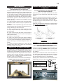
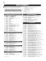
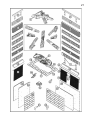
1
INSTALLER: THESE INSTRUCTIONS MUST BE CONVEYED TO AND REMAIN WITH THE HOMEOWNER.
CERTIFIED UNDER AMERICAN NATIONAL STANDARDS, ANSI Z21.11.2b, VOLUME II FOR UNVENTED ROOM HEATERS.
UNVENTED MILLIVOLT SYSTEM
INSTALLATION AND OPERATION INSTRUCTIONS FOR
UNVENTED GAS FIREPLACE - GVF40
GVF40N
MODEL GVF40P
NATURAL GAS MODEL
PROPANE GAS
CERTIFIED FOR CANADA AND UNITED STATES USING ANSI / CSA METHODS
WARNING: If the information in these instructions is not followed exactly, a fire or
explosion may result causing property damage, personal injury or death.
FOR YOUR SAFETY
Do not store or use gasoline or other flammable vapours and liquids in the vicinity
of this or any other appliance.
WHAT TO DO IF YOU SMELL GAS:
• Immediately call your gas supplier from
a neighbour's phone. Follow the gas
• Do not try to light any appliance.
supplier's instructions.
• Do not touch any electrical switch.
• If you cannot reach your gas supplier,
• Do not use any phone in your build
call the fire department.
ing.
Installation and service must be performed by a qualified installer, service agency
or the gas supplier.
This is an unvented gas-fired heater that uses air (oxygen) from the room in which it is
installed. Provisions for adequate combustion and ventilation air must be provided.
Wolf Steel Ltd., 24 Napoleon Rd., Barrie, ON L4M 4Y8 Canada • (705)721-1212 • fax(705)722-6031
www.napoleonfireplaces.com • [email protected]
W415-0319 / D / 08.03.05
2
TABLE of CONTENTS
Hood
Louvre Bracket
Hinge Screen
Louvre Installation & Removal
Heat Shield Stand Off Removal
Logo Placement
PG 3-4 INTRODUCTION
Warranty
General Instructions
General Information
Care of Glass Doors, Catalytic Tiles
& Plated Parts
16-17 OPTIONS
5-12 INSTALLATION
Combustion and Ventilation Air Provisions
Determining Confined or Unconfined Space
Gas Installation
Framing Dimensions
Peninsula Installation Procedure
Open End Installation Procedure
See-Thru Installation Procedure
Island Installation Procedure
13-15
Patented Catalytic Glass Door
Blower Installation
18-19 OPERATION / MAINTENANCE
Operating Instructions
Maintenance
Catalytic Tile Maintenance
Oxygen Depletion Sensor Pilot Cleaning
Pilot Flame Appearance
Venturi Adjustment
FINISHING
Log Placement
Glowing Embers
Charcoal Embers
Mantle Installation
Curtain Mesh
20-21 REPLACEMENTS
Ordering Replacement Parts
Replacement Parts
22-23 TROUBLE SHOOTING GUIDE
PLEASE RETAIN THIS MANUAL FOR FUTURE REFERENCE
WARNING
• Under no circumstances should this heater be modified.
• Provide adequate ventilation and combustion air. Provide adequate accessibility clearance for
servicing and operating the heater. Never obstruct the front opening of the heater.
• If heater shuts off, do not re-light until you provide fresh air. If heater keeps shutting off, have it
serviced. Keep burner and control compartment clean.
• Do not burn wood or other materials in this heater.
• Adults and especially children should be alerted to the hazards of high surface temperatures and
should stay away to avoid burns or clothing ignition. Keep young children and animals away
when the fireplace is hot.
• Due to high temperatures, the heater should be located out of traffic and away from furniture and
draperies.
• Clothing or other flammable material should not be placed on or near the heater.
• Any safety screen or guard removed for servicing must be replaced prior to operating the heater.
• It is imperative that the control compartments, burners and circulating air passageways in the
heater are kept clean. The heater should be inspected before use and at least annually by a
qualified service person. More frequent cleaning may be required due to excessive lint from
carpeting, bedding material, etc. The heater area must be kept clear and free from combustible
materials, gasoline and other flammable vapours and liquids.
• Furniture or other objects must be kept a minimum of 4 feet away from the front of the fireplace.
• Do not use this heater if any part has been under water. Immediately call a qualified service
technician to inspect the heater and to replace any part of the control system and any gas control which has been under water.
• Do not allow fans to blow directly into the fireplace. Avoid any drafts that alter burner flame
patterns.
• Do not use a blower insert, heat exchanger insert or other accessory not approved for use with
this heater.
ANY CHANGE TO THIS HEATER OR ITS CONTROLS CAN BE DANGEROUS AND IS PROHIBITED.
NOTE: CHANGES, OTHER THAN EDITORIAL, ARE DENOTED BY A VERTICAL LINE IN THE MARGIN
W415-0319 / D / 08.03.05
3
NAPOLEON gas fireplaces are manufactured under the strict Standard of the world recognized
ISO 9001 : 2000 Quality Assurance Certificate.
NAPOLEON products are designed with superior components and materials, assembled by trained craftsmen who take
great pride in their work. The burner and valve assembly are leak and test-fired at a quality test station. The complete
fireplace is test-fired and thoroughly inspected by a qualified technician before packaging to ensure that you, the
customer, receives the quality product that you expect from NAPOLEON.
NAPOLEON GAS FIREPLACE PRESIDENT'S LIFETIME LIMITED WARRANTY
The following materials and workmanship in your new NAPOLEON gas
as long as you own the fireplace. This covers: combustion chamber, heat
logs and embers, ceramic glass (thermal breakage only), gold plated parts
components and aluminum extrusion trims.
fireplace are warranted against defects for
exchanger, stainless steel burner, phazer™
against tarnishing, porcelainized enamelled
Electrical (110V and millivolt) components and wearable parts such as catalytic tiles, blowers, gas valves, thermal
switch, switches, wiring, remote controls, ignitor, gasketing, and pilot assembly are covered and NAPOLEON will
provide replacement parts free of charge during the first year of the limited warranty.
Labour related to warranty repair
the prior approval of an authorized
predetermined rate schedule and any
is covered free of charge during the first year. Repair work, however, requires
company official. Labour costs to the account of NAPOLEON are based on a
repair work must be done through an authorized NAPOLEON dealer.
CONDITIONS AND LIMITATIONS
NAPOLEON warrants its products against manufacturing defects to the original purchaser only -- i.e., the individual or legal entity (registered customer) whose name appears on the
warranty registration card filed with NAPOLEON -- provided that the purchase was made through an authorized NAPOLEON dealer and is subject to the following conditions and limitations:
This factory warranty is nontransferable and may not be extended whatsoever by any of our representatives.
The gas fireplace must be installed by a licenced, authorized service technician or contractor. Installation must be done in accordance with the installation instructions included with the
product and all local and national building and fire codes.
This limited warranty does not cover damages caused by misuse, lack of maintenance, accident, alterations, abuse or neglect and parts installed from other manufacturers will nullify this
warranty.
This limited warranty further does not cover any scratches, dents, corrosion or discolouring caused by excessive heat, abrasive and chemical cleaners nor chipping on porcelain enamel
parts, mechanical breakage of PHAZER™ logs and embers, nor any venting components used in the installation of the fireplace.
NAPOLEON warrants its stainless steel burners against defects in workmanship and material for life, subject to the following conditions: During the first 10 years NAPOLEON will replace
or repair the defective parts at our option free of charge. From 10 years to life, NAPOLEON will provide replacement burners at 50% of the current retail price.
In the first year only, this warranty extends to the repair or replacement of warranted parts which are defective in material or workmanship provided that the product has been operated
in accordance with the operation instructions and under normal conditions.
After the first year, with respect to this President's Limited Lifetime Warranty, NAPOLEON may, at its discretion, fully discharge all obligations with respect to this warranty by refunding
to the original warranted purchaser the wholesale price of any warranted but defective part(s).
After the first year, NAPOLEON will not be responsible for installation, labour or any other costs or expenses related to the reinstallation of a warranted part, and such expenses are not
covered by this warranty.
Notwithstanding any provisions contained in this President's Limited Lifetime Warranty, NAPOLEON’S responsibility under this warranty is defined as above and it shall not in any event
extend to any incidental, consequential or indirect damages.
This warranty defines the obligations and liability of NAPOLEON with respect to the NAPOLEON gas fireplace and any other warranties expressed or implied with respect to this product,
its components or accessories are excluded.
NAPOLEON neither assumes, nor authorizes any third party to assume, on its behalf, any other liabilities with respect to the sale of this product. NAPOLEON will not be responsible for:
over-firing, downdrafts, spillage caused by environmental conditions such as rooftops, buildings, nearby trees, hills, mountains, inadequate vents or ventilation, excessive venting configurations, insufficient makeup air, or negative air pressures which may or may not be caused by mechanical systems such as exhaust fans, furnaces, clothes dryers, etc.
Any damages to fireplace, combustion chamber, heat exchanger, brass trim or other component due to water, weather damage, long periods of dampness, condensation, damaging
chemicals or cleaners will not be the responsibility of NAPOLEON.
The bill of sale or copy will be required together with a serial number and a model number when making any warranty claims from your authorized dealer. The warranty registration card
must be returned within fourteen days to register the warranty.
NAPOLEON reserves the right to have its representative inspect any product or part thereof prior to honouring any warranty claim.
ALL SPECIFICATIONS AND DESIGNS ARE SUBJECT TO CHANGE WITHOUT PRIOR NOTICE DUE TO ON-GOING PRODUCT IMPROVEMENTS. NAPOLEON® IS A REGISTERED
TRADEMARK OF WOLF STEEL LTD. PATENTS U.S. 5.303.693.801 - CAN. 2.073.411, 2.082.915. © WOLF STEEL LTD.
W415-0319 / D / 08.03.05
4
GENERAL INSTRUCTIONS
THIS GAS FIREPLACE SHOULD BE INSTALLED AND
SERVICED BY A QUALIFIED INSTALLER to conform with
local codes. Installation practices vary from region to region and it is important to know the specifics that apply to
your area, for example: in Massachusetts State:
• The appliance off valve must be a “T” handle gas cock.
• The flexible connector must not be longer than 36 inches.
• The appliance is not approved for installation in a bedroom or
bathroom unless the unit is a direct vent sealed combustion
product.
• WARNING: This product must be installed by a licensed
plumber or gas fitter when installed within the commonwealth
of Massachusetts.
• Un-vented room heater shall be installed in accordance with
527 CMR 30.00 and 248 CMR 3.00 through 7.00.
• Sellers of un-vented propane or natural gas-fired
space/room heaters shall provide to each purchaser a copy
of 527 CMR 30.00 upon the sale of the unit from
http://www.napoleonfireplaces.com/Webshare/
installation_manuals/mass_requirements.pdf
In absence of local codes, install the GVF40 to the current
National Fuel Gas Code, ANSI Z223.1 Installation Code
which can be obtained from:
American Nation Standards Institute Inc.
1430 Broadway
New York, NY 10018
or
National Fire Protection Association Inc.
Batterymarch Park
Quincy, MA 02269
The fireplace and its individual shutoff valve must be disconnected from the gas supply piping system during any
pressure testing of that system at test pressures in excess of 1/2 psig (3.5 kPa). The fireplace must be isolated
from the gas supply piping system by closing its individual
manual shutoff valve during any pressure testing of the
gas supply piping system at test pressures equal to or
less than 1/2 psig (3.5 kPa).
When the fireplace is installed directly on carpeting, vinyl
tile or other combustible material other than wood flooring, the fireplace shall be installed on a metal or wood
panel extending the full width and depth.
If the optional fan or blower is installed, the junction box
must be electrically connected and grounded in accordance with local codes. In the absence of local codes, use
the current ANSI/NFPA 70 NATIONAL ELECTRICAL CODE
in the United States.
GENERAL INFORMATION
FOR YOUR SATISFACTION, THIS FIREPLACE HAS BEEN
TEST-FIRED TO ASSURE ITS OPERATION AND QUALITY! Maximum input is 30,000 BTU/hr for natural gas and
28,500 BTU/hr for propane. When the fireplace is installed
at elevations above 2,000ft, and in the absence of specific
recommendations from the local authority having jurisdiction, the certified high altitude input rating shall be reduced
at the rate of 4% for each additional 1,000ft.
This heater must not be installed in a bedroom or
bathroom.
W415-0319 / D / 08.03.05
This fireplace may be installed in an aftermarket permanently located, manufactured (mobile) home, where
not prohibited by local codes.
This fireplace is only for use with the type of gas indicated on the rating plate. This fireplace is not convertible for use with other gases, unless a certified kit is
used.
Minimum inlet gas supply pressure is 4.5 inches water
column for natural gas and 11 inches water column for
propane. Maximum inlet gas pressure is 7 inches water
column for natural gas and 13 inches water column for
propane. Manifold pressure under flow conditions is 3.5
inches water column for natural gas and 10 inches water
column for propane.
No external electricity (110 volts or 24 volts) is required
for the gas system operation.
Expansion / contraction noises during heating up and cooling down cycles are normal and are to be expected.
CARE OF OPTIONAL GLASS DOORS,
CATALYTIC TILES AND PLATED PARTS
Do not use abrasive cleaners to clean plated parts. Buff
lightly with a clean dry cloth. This fireplace may have optional glass doors which are equipped with either 3/16"
thick tempered or ceramic glass. Use only replacement
glass available from your Napoleon dealer. DO NOT SUBSTITUTE MATERIALS. Clean the glass after the first 10
hours of operation with a recommended gas fireplace
glass cleaner. Thereafter clean as required. DO NOT
CLEAN GLASS WHEN HOT! If the glass is not kept clean
permanent discolouration and / or blemishes may result.
Catalytic tiles normally do not require cleaning. Physical
contact should be avoided. See Maintenance.
This heater is equipped with a pilot light safety
system referred to as an OXYGEN DEPLETION
SENSOR and is designed to turn off the heater if
not enough fresh air is available.
Use only accessories designed for and
listed with your specific fireplace.
CARBON MONOXIDE POISONING
MAY LEAD TO DEATH
Early signs of carbon monoxide poisoning resemble the flu, with headache, dizziness and/
or nausea. If you have these signs, the heater
may not be working properly. Get fresh air
at once! Have heater serviced.
Some people---pregnant women, persons
with heart or lung disease, anaemia, those
under the influence of alcohol, those at high
altitudes--- are more affected by carbon monoxide than others.
5
INSTALLATION
COMBUSTION AND VENTILATION
AIR PROVISIONS
This heater shall not be installed in a confined
space or unusually tight construction unless provisions are provided for adequate combustion and
ventilation air.
In order to avoid the possibility of exposed insulation or vapour barrier coming in contact with
the fireplace body, it is recommended that the
walls of the fireplace enclosure be 'finished', (i.e.
drywall/sheetrock) as would any other outside
wall of the home. This will ensure that clearance
to combustibles is maintained within the cavity.
The National Fuel Gas Code, ANSI Z223.1 defines a confined space as a space whose volume is less than 50
cubic feet per 1,000 Btu per hour (4.8 m3 per kW) of the
aggregate input rating of all appliances installed in that
space and an unconfined space as a space whose volume is not less than 50 cubic feet per 1,000 BTU per hour
(4.8 m3 per kW) of the aggregate input rating of all appliances installed in that space. Rooms communicating directly with the space in which the appliances are installed,
through openings not furnished with doors are considered a part of the unconfined space.
The GVF40 is rated at 30,000BTUs per hour for
natural gas and 28,500 BTUs for propane and
therefore requires a minimum unconfined space
of 1,500 and 1,425 cubic feet respectively.
DETERMINING CONFINED OR
UNCONFINED SPACE
Unusually tight construction is defined as construction where:
a) Walls and ceilings exposed to the outside atmosphere have a continuous water vapour retarder with a
rating of 1 perm (6 x 10-11 kg per pa-sec-m2) or less with
openings gasketed or sealed, and
b) Weather stripping has been added on openable
windows and doors, and
c) Caulking or sealants are applied to areas such as
joints around window and door frames, between sole
plates and floors, between wall-ceiling joints, between
wall panels, at penetrations for plumbing, electrical, and
gas lines, and at other openings.
An unvented room heater is recommended for use as a
secondary heat source rather than as a primary source.
Gas combustion produces water vapour which could occur at the rate of approximately one ounce of water for
every 1,000 BTU/hr of gas input. During the cold weather
season, indoor humidity levels tend to be low. Consequently, this water vapour can enhance the living space.
However if a problem should occur:
a) ensure sufficient combustion and circulation air
b) use a dehumidifier
c) do not use the unvented room heater as a primary
heat source
Without sufficient fresh air for proper operation, poor fuel
combustion can result. Carbon Monoxide is a result of
poor combustion.
If additional fresh air is required, use one of the methods described in the National Fuel Gas Code, ANSI Z223.1,
Section 5.3 or the applicable local code.
To determine the volume of the room where the heater is
to be installed, multiply the width x the length x the ceiling
height of that room measured in feet. If any adjoining rooms
are connected by grills or openings such as kitchen passthroughs, etc., the volume of those rooms may be added to
the total.
Multiply the room volume by 1000 and divide this amount
by 50 to determine the maximum Btu/hr that the space can
support with adequate combustion and ventilation air.
Add the BTU/hr of all fuel burning appliances located within
the space such as gas furnace, gas water heater, etc. Do
not include direct vent gas appliances which draw their
input and output air from and to the outdoors.
WARNING: If the area in which the heater may be operated is smaller than that defined as an unconfined space
or if the building is of unusually tight construction, provide
adequate combustion and ventilation air by one of the
methods described in the National Fuel Gas Code ANSI
Z223.1, Section 5.3 or the applicable local code.
W415-0319 / D / 08.03.05
6
FIGURE 1
ROOM 2
ROOM 1
HEIGHT
If for example,
the length of the
rooms is 10 feet,
the width of Room 1
is 10 feet,
the width of Room 2
is 15 feet
the height of the
rooms is 8 feet.
The volume of Room 1: 10 x 10 x 8 =
800 cubic feet.
The volume of Room 2: 10 x 15 x 8 = 1200
cubic feet.
LENGTH
Room Volume = Length x Width x Height
Max BTU/hr = Room Volume x 1000 ÷ 50
EXAMPLE 1
EXAMPLE 2
In this example, because there is no door to the adjoining
room, the volume of the adjoining room may be added to
the volume of the room with the heater to get a total
unconfined space.
If in this example a solid door separates Room 1 from
Room 2, the volume of Room 2 could not be used. In this
case the maximum BTU/h would be:
Maximum BTU/h:
The total unconfined space: 800 + 1200 = 2000 cubic feet.
Maximum BTU/h:
2000 x 1000
50
= 40,000 BTU/h
If there are no more fuel burning appliances within this
space then the 30,000 BTU/h input of the fireplace is suitable to be installed. This also assumes that the construction of this space is not unusually tight.
800 x 1000
50
= 16,000 BTU/h
This would be considered a confined space since it can
not support the 30,000BTU/h input of the heater and it
would be necessary to provide adequate combustion and
ventilation air to Room 1.
GAS INSTALLATION
5. Attach the two leads to terminals 1 and 3 located on
the gas valve.
O
ON
PLT
FIGURE 3
1
2
LO
DO NOT KINK FLEX CONNECTOR.
MAX. LENGTH
100 feet
60 feet
40 feet
FF
FIGURE 2
WIRE SIZE
14gauge
16gauge
18gauge
IH
1. Move the fireplace into position and secure to the floor
through the ¼"ø holes located at the four outside corners
of the base.
2. Install rigid black pipe, 1/2" type-L copper tubing or, if
local codes permit, a 3/8" flex connector and shutoff valve
to the gas line and the fireplace gas valve. Seal and tighten
securely. An adapter fitting is required between the gas
valve and the copper tubing or flex connector.
O I
3. Check for gas leaks by brushing on a soap and water
solution.
DO NOT USE OPEN FLAME.
4. For ease of accessibility, an optional remote wall
switch or millivolt thermostat may be installed in a convenient location. Route a 2 strand, solid core millivolt wire
through the electrical hole located at the bottom left side of
the unit. The recommended maximum lead length depends on wire size:
W415-0319 / D / 08.03.05
PI L OT
3
Do not connect either the wall switch, thermostat or
gas valve to electricity (110 volts).
6. Mark the appropriate boxes on the rating plate label to
indicate the model type.
USING DOOR OPTION:
Purge all gas lines with the glass door of the fireplace
opened. Assure that a continuous gas flow is at the
burner before closing the door.
7
4-SIDED
FIGURES 4 a-d
SEE-THRU
OPEN-END
PENINSULA
W415-0319 / D / 08.03.05
8
PENINSULA INSTALLATION PROCEDURE
FRAMING
COUNTERTOP / BAR INSTALLATION
Note: In order to avoid the possibility of exposed insulation or vapour barrier coming in contact with the
fireplace body, it is recommended that the walls of the
fireplace enclosure be “finished” (ie: drywall/sheetrock),
as you would finish any other outside wall of a home.
This will ensure that clearance to combustibles is
maintained within the cavity.
It is best to frame your fireplace after it is positioned. Use
2x4's and frame to local building codes. FIGURE 5.
When finishing the fireplace, combustible material may
rest directly on of the top extension.
Note: Maximum weight tolerance is 400 lbs, provided
that it is evenly distributed across the top extensions
of the fireplace.
In order to achieve a countertop or bar type appearance
with the minimum height allowed, framing must be noncombustible and may be done with metal studding attached to the heat shield sides or the upper frame of the
fireplace. FIGURE 7.
A
FIGURE 5
FIGURE 7
A = 22 " minus finishing material thickness each side.
To install the fireplace face flush with the finished wall,
position the framework to accommodate the thickness
of the finished wall.
FIGURE 6
* The top extension may be removed if non-combustible
framing is faced with a non-combustible material placed
flush with the front face of the unit and extending from the
top of the unit. (Example: cement board) (not supplied).
Combustible counter / bar tops must maintain a minimum
of 38 inches from the base of the fireplace to the underside
of the top. Figure 8.
FIGURE 8
TOP EXTENTION
TOP OF THE UNIT
NOTE: Wolf Steel trim and/or surround kits will not totally cover the top extension of the fireplace. In order to
obtain a smooth transition from the trim / surround to
the wall, it is recommended that the top extension be
removed and the unit be installed following the above
procedure.
W415-0319 / D / 08.03.05
9
BRICK PANEL INSTALLATION
FACING
Install the base panels as illustrated in steps 1-4 . The
side panel sits under the bracket tab. Holding the side
panel in position, bend down the tab to secure. [DETAIL 5.]
Combustible materials may be installed flush with the front
of the fireplace but must not cover any of the black faceareas of the fireplace. Non-combustible material (brick,
stone or ceramic tile) may protrude in these areas.
It is not necessary to install a hearth extension with this
fireplace system.
FIGURES 9a-e
STEP 1
When roughing in the fireplace, raise the fireplace to accommodate for the thickness of the finished floor materials, i.e. tile, carpeting, hard wood, which if not planned for
will interfere with the opening of the lower access door and
the installation of many decorative flashing accessories.
Objects placed in front of the fireplace should be
kept a minimum of 48" away from the glass front
faces of the fireplace.
FIGURE 10
STEP 2
DRYWALL
DRYWALL
STEP 3
4" MIN
STEP 4
FINISHING
Refer to pages 13-15 for complete instructions regarding
mantle requirements and installations, log placement,
glass door and upper and lower louvre attachments.
RETAINER
STEP 5
DETAIL 5
W415-0319 / D / 08.03.05
10
OPEN-END INSTALLATION PROCEDURE
FRAMING
Note: In order to avoid the possibility of exposed insulation or vapour barrier coming in contact with the
fireplace body, it is recommended that the walls of the
fireplace enclosure be “finished” (ie: drywall/sheetrock),
as you would finish any other outside wall of a home.
This will ensure that clearance to combustibles is
maintained within the cavity.
It is best to frame your fireplace after it is positioned and
the vent system is installed. Use 2x4's and frame to local
building codes. FIGURE 11.
See PAGE 8 for bar type / countertop installation.
FIGURES 13 a-c
STEP 5
FIGURE 11
RETAINER
IH
O
LO
O
FF P
L
DETAIL 6
STEP 6
FACING
FIGURE 12
Combustible materials may be installed flush with the front
of the fireplace but must not cover any of the black faceareas of the fireplace. Non-combustible material (brick,
stone or ceramic tile) may protrude in these areas.
It is not necessary to install a hearth extension with this
fireplace system.
When roughing in the fireplace, raise the fireplace to accommodate for the thickness of the finished floor materials, i.e. tile, carpeting, hard wood, which if not planned for
will interfere with the opening of the lower access door
and the installation of many decorative flashing accessories.
Objects placed in front of the fireplace should be
kept a minimum of 48" away from the glass front
faces of the fireplace.
A
A = 25¼" minus finishing material thickness each side.
NOTE: LEFT CORNER UNIT ILLUSTRATED
To install the fireplace face flush with the finished wall,
position the framework to accommodate the thickness
of the finished wall.
BRICK PANEL INSTALLATION
Install the base panels as illustrated in steps 1-4 on page
9. The side panel sits under the bracket tab. Holding the
side panel in position, bend down the tab to secure. [DETAIL 6].
W415-0319 / D / 08.03.05
FINISHING
Refer to pages 13-15 for complete instructions regarding
mantle requirements and installations, log placement,
glass door and upper and lower louvre attachments.
FIGURE 14
DRYWALL
DRYWALL
4" MIN
11
SEE-THROUGH INSTALLATION PROCEDURE
FRAMING
FACING
Note: In order to avoid the possibility of exposed insulation or vapour barrier coming in contact with the
fireplace body, it is recommended that the walls of the
fireplace enclosure be “finished” (ie: drywall/sheetrock),
as you would finish any other outside wall of a home.
This will ensure that clearance to combustibles is
maintained within the cavity.
It is best to frame your fireplace after it is positioned and
the vent system is installed. Use 2x4's and frame to local
building codes. FIGURE 15.
See PAGE 8 for bar type / countertop installation.
Combustible materials may be installed flush with the front
of the fireplace but must not cover any of the black faceareas of the fireplace. Non-combustible material (brick,
stone or ceramic tile) may protrude in these areas.
It is not necessary to install a hearth extension with this
fireplace system.
When roughing in the fireplace, raise the fireplace to accommodate for the thickness of the finished floor materials, i.e. tile, carpeting, hard wood, which if not planned for
will interfere with the opening of the lower access door
and the installation of many decorative flashing accessories.
FIGURE 15
Objects placed in front of the fireplace should be
kept a minimum of 48" away from the glass front
faces of the fireplace.
FINISHING
Refer to pages 13-15 for complete instructions regarding
mantle requirements and installations, log placement,
glass door and upper and lower louvre attachments.
FIGURE 17
A
DRYWALL
DRYWALL
A = 22" minus finishing material thickness, each side.
BRICK PANEL INSTALLATION
Install the base panels as illustrated in steps 1-4 on page
9. Both side panels sit under the bracket tab. Holding the
side panel in position, bend down the tab to secure. [DETAIL 6].
FIGURES 16 a-c
4" MIN
RETAINER
STEP 5
RETAINER
DETAIL 5 & 6
STEP 6
W415-0319 / D / 08.03.05
12
ISLAND INSTALLATION PROCEDURE
FRAMING
BRICK PANEL INSTALLATION
Note: In order to avoid the possibility of exposed insulation or vapour barrier coming in contact with the
fireplace body, it is recommended that the walls of the
fireplace enclosure be “finished” (ie: drywall/sheetrock),
as you would finish any other outside wall of a home.
This will ensure that clearance to combustibles is
maintained within the cavity.
It is best to frame your fireplace after it is positioned. Use
2x4's and frame to local building codes. FIGURE 18.
Install the base panels as illustrated in steps 1-4 on page
9.
A
FIGURE 18
FACING
Combustible materials may be installed flush with the front
of the fireplace but must not cover any of the black faceareas of the fireplace. Non-combustible material (brick,
stone or ceramic tile) may protrude in these areas.
It is not necessary to install a hearth extension with this
fireplace system.
When roughing in the fireplace, raise the fireplace to accommodate for the thickness of the finished floor materials, i.e. tile, carpeting, hard wood, which if not planned for
will interfere with the opening of the lower access door
and the installation of many decorative flashing accessories.
Objects placed in front of the fireplace should be
kept a minimum of 48" away from the glass front
faces of the fireplace.
FIGURE 20
A = 22 " minus finishing material thickness each side.
To install the fireplace face flush with the finished wall,
position the framework to accommodate the thickness
of the finished wall.
FIGURE 19
DRYWALL
DRYWALL
FINISHING
W415-0319 / D / 08.03.05
Refer to pages 13-15 for complete instructions regarding
mantle requirements and installations, log placement,
glass door and upper and lower louvre attachments.
13
FINISHING
LOG PLACEMENT
E
TM
PHAZER logs, glowing and charcoal embers, exclusive
to Napoleon fireplaces, provide a unique and realistic glowing effect that is different in every installation. Take the time
to carefully position the embers for a maximum glowing
effect. Figures 21 A - H.
A
#1
LOCATING PINS
#3
LOCATING PINS
5. When pieces #3a and #3b are attached to create log
#3, the upper end of log #3 should rest in the groove, on
top of log # 2.
F
1. Place log #1 diagonally across the textured burner cover
onto the pins. The texture is designed to cradle the underside of the log.
#4
#2
B
6. As with log # 1, log #4 is also cradled by the texture of the
burner cover and the pin in the base. Position log #4 so that
the lower end fits onto the pin. The upper end rests against
the moulded locater on the top of log # 1.
7. Like log #3, log #5
also comes in two
pieces. The base
(#5a) slopes
outwards between
logs #2 and #4.
As with pieces #3a &
b, piece #5b fits over
piece #5a. Place the
end of piece #5b
onto the pin.
G
#5
b
2. Depending on the type of installation, the view of the log
positioning will reverse. Here the lower end of log #2 rests
near the back left corner of the firebox on the locating pin.
The upper end sits on top of log #1, inside the groove on
log #2.
C
a
#3a
#2
H
#5
#3
D
b
a
3. Log # 3 is made up of
two pieces, a and b. Piece
#3a is the base of log #3.
The base sits diagonally in
the designated area located between logs #1 and
fits tight up against #2.
4. The slot in the underside of piece #3b fits over
#3a. Place the end of
piece #3b onto the pin.
#3
#1
#4
8. The upper end of log #5 rests in the groove, on top of
log #4 and creates the final appearance of the log set.
W415-0319 / D / 08.03.05
14
GLOWING EMBERS
Tear the embers into small pieces and place on the ported
area of the burner. Care should be taken to shred the
embers into thin, small irregular pieces as only the exposed edges of the fibre hairs will glow. The ember material will only glow when exposed to direct flame; however,
care should be taken to not block the burner ports. Blocked
burner ports can cause an incorrect flame pattern, carbon
deposits and delayed ignition. PHAZERTM logs glow when
exposed to direct flame.
Dashed lines are suitable
mantle sizes and clearances when a non-combustible facing is used.
FIGURE 25
HOOD
HOOD
FIGURE 26
CHARCOAL EMBERS
Randomly place the embers around the bottom brick panels in a realistic manner but not in contact with the flames.
Keep ember dust away from burner ports to avoid plugging
them.
CURTAIN
MESH
Fine dust found in bottom of bag not to be used. PHAZERTM
logs, and embers glow when exposed to direct flame. Use
only certified PHAZERTM logs, glowing embers and charcoal embers available from your Napoleon / Wolf Steel Ltd.
dealer.
GLOWING EMBERS
The curtain mesh must be kept fully closed during operation to help prevent accidental burns from occurring.
CURTAIN SUPPORT
PLATE
HOOD
The heater must
not be used when
the hood is removed. Hook the
hood over the lip of
the curtain support
plate.
FIGURE 27
22
Ensure that glowing embers sufficiently cover the carry over
ports, highlighted below, to achieve maximum glow.
CARRY OVER PORTS
UPPER LOUVRE BRACKETS & HOOD
FIGURE 28
FIGURE 23
MANTLE INSTALLATION
Combustible mantle clearance can vary according to the
mantle depth. Use the graph to help evaluate the clearance needed. The four-sided top extension piece may be
removed if non-combustible framing is faced with a noncombustible material.
FIGURE 24
W415-0319 / D / 08.03.05
Attach the hood with louvre brackets by pressing the top
flange of the bracket into the clips along the top of the
louvre opening with louvre securing tabs facing out.
15
LOWER LOUVRE BRACKETS & HINGE SCREEN
A
B
UPPER LOUVRES
Insert the louvre tabs into the
slots located at the top left and
right corners of the unit.
SLOT
TA B
FIGURES 29
Using 6 screws, attach the lower louvre brackets and hinge
screen as illustrated. Be sure to install the louvre brackets over the hinge screen.
B
C
HINGE
LOWER LOUVRES
Insert the hinge clips into the
slots located at the bottom left
and right corners of the unit.
To remove the louvres, pull the
back tabs of the clips forward,
while pushing the louvre assembly back. Lift the clip.
SLOT
CLIP
GVFL INSTALLATION
TO INSTALL THE UPPER LOUVRES: Insert
the upper louvres into
the slots on both brackets. Press the top flange
of the hood into the four
clips located along the
top of the unit as shown.
HOOD
BRACKET
SLOT
30
LOUVRE
31
LOWER LOUVRES
(VALVE CONTROL DOOR)
HEAT SHIELD STAND-OFF
REMOVAL
TO INSTALL THE
LOWER LOUVRE ASSEMBLY: Attach each
hinge to the firebox with
2 screws.
HE
AT
S
HIE
LD
L36 LOUVRE INSTALLATION
FIGURE 32 a-c
A
STA
ND
FIGURE 33
B
-OF
FS
END HEAT SHIELD SHOWN
When using a non-combustible finishing material, the
stand-offs may be removed, by removing the set screw in
the centre and sliding the stand-offs out of the mounting
clips.
LOGO PLACEMENT
C
Remove the backing of
the logo supplied and
place on the screen
cover, as indicated.
A
CLIPS
FLANGE
CENTRE
SLOT
HOOD
Attach the hood by pressing the
top flange into the clips along
the top of the louvre opening.
Secure using a screw through
the centre slot.
FIGURE 34
W415-0319 / D / 08.03.05
16
OPTIONS
GVF103-KT - PATENTED CATALYTIC
DOOR INSTALLATION
Notes:
Ornamental insets can not be used in conjunction
with the catalytic door
When using a catalytic door, glassed doors must
be used on all other side or end openings.
This unique patented catalytic system was designed to
provide unparalleled safety and peace of mind. The top of
the door contains four catalytic tiles which are designed to
filter out combustion gases and limit the carbon monoxide output. It is likely that with the fireplace in operation, the
catalytic tiles will actually scrub the carbon monoxide normally found in the room and reduce it to a lower level. The
tiles must not be altered or removed. They are not field
serviceable and must be tested annually. The hood supplied with the unit must be disgarded and replaced with
the hood designed for use with the catalytic door.
The heater with an optional catalytic door in place must
not be operated when using any products such as paint,
paint thinner, adhesives, etc. These products will permanently affect the catalytic tiles’ ability to scrub the air.
FIGURES 35
3. Screw the door hinge
onto the heater by first starting each of the five machine screws and then
tightening all screws.
DOOR
HINGE
3
TOP DOOR LATCH
4
CURTAIN ROD
BRACKET
BOTTOM DOOR LATCH
1
1. The mesh must be removed if the catalytic door is used.
Remove the centre bracket and bend the curtain rod slightly
to disengage the rod from either side.
4. & 5. Secure the door using the two latches.
Install the appropriate hood by hooking it over the top lip of
the door assembly.
The heater must not be used when the hood is removed.
LATCH SCREW
LOCATION
CURTAIN SUPPORT PLATE
DOOR OPENING AND CLOSING
2
2. Remove the curtain support plate. Remove the two latch
securing screws, already installed, position latch as shown
in 4 and re-secure with the screws. A ¼” socket ratchet is
recommended for this.
Repeat at the bottom. For location, see 5 .
W415-0319 / D / 08.03.05
5
FLANGE
HOOD
The upper louvres must
be removed to allow the
catalytic door to be
opened or closed. To access the lower door latch,
open the valve control
UPPERLOUVRE
door. Release the top and
bottom door latches, located at the right side of
DOOR LATCH
36
the door.
Care must be taken when closing and opening the catalytic door to avoid damaging the catalytic tiles.
CLIP
17
OPTIONAL BLOWER INSTALLATION
THIS BLOWER IS NOT RECOMMENDED FOR THE 4 SIDED INSTALLATION.
THERMODISC WIRES TO BLOWER
THERMODISC BRACKET
blac
INSTALLATION TO BE DONE BY A QUALIFIED INSTALLER and must be electrically connected and
grounded in accordance with local codes. In the absence
of local codes, use the current ANSI/NFPA 70 NATIONAL ELECTRICAL CODE in the United States.
Remove
the
blower from its
mounting bracket
r ed
and attach to the
bracket supplied
with the fireplace.
white
This bracket is
FIGURE 37
found secured on
the mounting stud
located at the bottom of the vent
side wall.
k
FIGURE 38
FIGURE 39
The blower bracket contains two holes that allow the blower
to be positioned away from the intended gas supply hole.
Position the vibration reducing pad, centred, onto the
threaded stud, piercing a hole into the pad. The blower
must be able to be positioned entirely onto the pad.
Tilt the blower onto its side and slide it past the controls.
Position the blower under the clip and onto the stud. Secure with a wing nut.
FIGURE 41
Remove the thermodisc bracket from the top of the firebox.
Remove the thermodisc from the bracket supplied in the
blower kit and install the thermodisc into the fireplace
bracket. Then replace the bracket in the location it was
removed.
Connect the two ends of the unattached wires by the bracket
to the thermodisc.
Connect the opposite ends of the wires to the red and black
leads of the blower harness.
The wire harness provided in this kit is a universal harness. When installed, ensure that any excess wire is
contained, preventing it from making contact with moving or hot objects.
Drywall dust will penetrate into the blower bearings, causing irreparable damage. Care must be taken to prevent
drywall dust from coming into contact with the blower or
its compartment. Any damage resulting from this condition is not covered by the warranty policy.
Because the blower is thermally activated, when turned
on, it will automatically start approximately 10 minutes
after lighting the fireplace and will run for approximately
30 - 45 minutes after the fireplace has been turned off.
Use of the fan increases the output of heat.
FIGURE 40
W415-0319 / D / 08.03.05
18
OPERATION / MAINTENANCE
If heater shuts off, do not relight until you provide
fresh air. If heater keeps shutting off, have it serviced. Keep burner and control compartment clean.
When lit for the first time, the fireplace will emit a slight
odour for a few hours. This is a normal temporary condition caused by the curing of the logs and the "burn-in" of
internal paints and lubricants used in the manufacturing
process and will not occur again.
After extended periods of non-operation such as following
a vacation or a warm weather season, the fireplace may
emit a slight odour for a few hours. This is caused by dust
particles burning off. In both cases, open a window to sufficiently ventilate the room.
Purge the gas line with the glass door open. Assure
that a continuous gas flow is at the burner before closing the door.
FOR YOUR SAFETY READ BEFORE LIGHTING:
WARNING: IF YOU DO NOT FOLLOW THESE INSTRUCTIONS EXACTLY, A FIRE OR EXPLOSION MAY RESULT CAUSING PROPERTY DAMAGE, PERSONAL INJURY OR LOSS OF LIFE.
• Do not try to light any appliance.
• Do not touch any electric switch; do not use any phone
in your building.
• Immediately call your gas supplier from a neighbour's
phone. Follow the gas supplier's instructions.
• If you cannot reach your gas supplier, call the fire department.
L T
ON
FF
P
O
C. Use only your hand to push in and turn the gas control
knob. Never use tools. If the knob will not push in and
turn by hand, do not try to repair it. Call a qualified
service technician. Force or attempted repair may result in a fire or explosion.
D. Do not use this fireplace if any part has been under
water. Immediately call a qualified service technician to
inspect the fireplace and replace any part of the control
system and any gas control which has been under water.
WHAT TO DO IF YOU SMELL GAS:
O I
A. This fireplace is equipped with a pilot which must be
lit by hand while following these instructions exactly.
B. Before operating smell all around the fireplace area
for gas and next to the floor because some gas is
heavier than air and will settle on the floor.
OXYGEN DEPLETION SENSOR
GAS KNOB
LIGHTING INSTRUCTIONS
When lighting and re-lighting, the gas knob cannot be
turned from pilot to off unless the knob is depressed.
1. STOP! Read the above safety information on this label.
2. Set the thermostat to lowest setting.
3. Turn off all electric power to the fireplace.
4. Open the control door. Turn the gas knob clockwise
to off.
5. Wait five (5) minutes to clear out any gas. If you smell
gas including near the floor, STOP! Follow "B" in the
above safety information on this label. If you don't smell
gas go to the next step.
6. Find pilot located in front of the back log.
7. Turn gas knob counter-clockwise
to pilot.
8. Depress and hold gas knob while lighting the pilot
with the push button igniter. Keep knob fully depressed
for one minute, then release. If pilot does not continue
to burn repeat steps 3 through 7.
9. With pilot lit, turn gas knob counter-clockwise
to
on. When the pilot has been turned off, ignition of the
main burner may be delayed from 1-2 minutes.
When the pilot has been left burning, ignition of the
main burner should occur almost immediatley.
10. If equipped with remote on-off switch, main burner
may not come on when you turn the valve to on. Remote switch must be in the on position to ignite burner.
11. Turn on all electric power to the fireplace.
GAS KNOB AT OFF
O
LO
ON
FF
IH
PLT
O I
PI LOT
TO TURN OFF GAS
1. Turn off all electric power to the fireplace if service is to
be performed.
W415-0319 / D / 08.03.05
2. Push in gas control knob slightly and turn clockwise
to off. Do not force.
19
MAINTENANCE
TURN OFF THE GAS AND ELECTRICAL POWER
BEFORE SERVICING THE FIREPLACE.
CAUTION: Label all wires prior to disconnection when
servicing controls. Wiring errors can cause improper and
dangerous operation. Verify proper operation after servicing. This heater should be inspected and serviced before
use and at least annually by a qualified service person.
The fireplace area must be kept clear and free of combustible materials, gasoline or other flammable vapours and
liquids. The flow of combustion and ventilation air must
not be obstructed.
1. In order to properly clean the burner and oxygen depletion sensor system, remove the logs to expose both assemblies.
2. Keep the control compartment, logs, burner, air shutter
opening and the area surrounding the logs clean by vacuuming or brushing, at least once a year.
3. Check to see that all burner ports are burning. Clean
out any of the ports which may not be burning or are not
burning properly.
4. Check to see that the pilot flame is large enough to
engulf the thermocouple and thermopile and promptly ignites the main burner.
5. Replace the cleaned logs.
6. Check to see that the main burner ignites completely
on all openings when the gas knob for the burner is turned
on. A 5 to 10 second total light-up period is satisfactory. If
ignition takes longer, consult your Napoleon dealer / distributor.
7. If using an optional catalytic door, check that the
gasketing on the sides, and top of the door is not broken
or missing. Replace if necessary.
CATALYTIC TILE MAINTENANCE
The catalytic tile is not field serviceable. It may only be
handled or replaced by a qualified service person familiar
with the specific characteristics of the appliance. Both room
values and output from the catalytic tiles must be checked.
Check the room value with the heater off. Check the fireplace value after 10 minutes of heater operation to allow
the tiles to come up to temperature.
In both cases the value of CO should not exceed 9ppm.
Catalytic output must be checked annually at the
beginning of the heating season.
OXYGEN DEPLETION SENSOR PILOT
CLEANING
THIS PROCEDURE MUST BE PERFORMED BY A
QUALIFIED SERVICE PERSON!
Inspect the pilot for any visible contamination or debris
(usually lint, pet hair, spider webs, carpet fibre, etc.) and
remove.
Disconnect the pilot from the pilot tubing line. Using a 7/16”
wrench, remove the injector from the pilot housing. Blow
out the housing in the same direction as the gas flow.
Re-install the injector and the pilot tube, turn on the gas
and check for leaks.
If this does not improve the performance, replace the pilot
with an exact replacement. The device is tamper resistant with no field serviceable parts.
CORRECT PILOT
FLAME
INCORRECT PILOT
FLAME
FIGURES 43
VENTURI ADJUSTMENT
AIR SHUTTER ADJUSTMENT MUST ONLY BE DONE
BY A QUALIFIED GAS INSTALLER!
Closing the air shutter will cause a more yellow flame, but
can lead to carboning. WARNING: Carbon can be distributed in surrounding living area if the air shutter is improperly adjusted.
Opening the air shutter will cause a more blue flame, but
can cause flame lifting from the burner ports. The flame
may not appear yellow immediately; allow 15 to 30 minutes for the final flame colour to be established.
Opening the air shutter will also reduce exhaust odours
smelled within the room. See Trouble Shooting Guide.
AIR SHUTTER OPENINGS
CATALYTIC TILE
NG
14
LP
7 16
/"
/ "
FIGURES 44
VENTURI
FIGURE 42
W415-0319 / D / 08.03.05
20
REPLACEMENTS
Contact your dealer for questions concerning prices and
availability of replacement parts. Normally all parts can be
ordered through your Napoleon dealer or distributor.
FOR WARRANTY REPL
ACEMENT PAR
TS, A PHO
TOCOPY OF THE
REPLA
ARTS
PHOT
ORIGINAL INVOICE WILL BE REQUIRED TO HONOUR THE CLAIM.
When ordering replacement parts always give the following information:
1. MODEL & SERIAL NUMBER OF FIREPLACE
2. INSTALLATION DATE OF FIREPLACE
3. PART NUMBER
4. DESCRIPTION OF PART
5. FINISH
6. TOP OR REAR VENT
* IDENTIFIES ITEMS WHICH ARE NOT ILLUSTRATED. FOR FURTHER INFORMATION, CONTACT YOUR NAPOLEON DEALER.
COMPONENTS COMMON TO ALL UNITS
#
PART No.
1*
2*
3*
4*
5
6
7
8
9
10
11
12
13
14
15
16
17
18
19
20
21
22
23
24
W361-0016
W550-0001
GD660
W385-0245
GL-634
W135-0153
W135-0154
W135-0155
W135-0156
W135-0157
W135-0158
W135-0159
W475-0259
W475-0260
W475-0278
W475-0262
W080-0519
W335-0024
W565-0058
W555-0033
W080-0357
W630-0010
W500-0194
N010-0279
DESCRIPTION
GLOWING EMBERS
CHARCOAL EMBERS
STANDARD WALL SWITCH & 20FT OF WIRE
NAPOLEON LOGO
BGD40 LOGSET
LOG#1
LOG#2
LOG#3 - PIECE A
LOG#3 - PIECE B
LOG#4
LOG#5 - PIECE A
LOG#5 - PIECE B
END FIBRE BRICK PANEL - FOR BURNER
END FIBRE BRICK PANEL - FOR BURNER
SIDE FIBRE BRICK PANEL - FOR BURNER
SIDE FIBRE BRICK PANEL - FOR BURNER
BOTTOM LOUVRE BRACKET
HOOD
CURTAIN MESH
CURTAIN ROD
CURTAIN ROD BRACKET
BLACK TASSELS
CURTAIN SUPPORT PLATE
SIDE LOUVRE HOOD W/ LOUVRE BRACKETS
COMPONENTS UNIQUE TO OPEN END UNIT
25
26
27
28
29
30
31
32
33
34
35
36
W200-0114
N010-0327
W475-0263
W500-0192
W335-0027
W565-0060
W555-0039
N010-0310
W585-0126
N010-0323
W500-0192
W475-0265
SIDE DOOR COVER
SIDE DOOR HEAT SHIELD
SIDE BRICK PANEL - FOR WALL
SIDE BRICK PANEL RETAINER
SHORT HOOD
SHORT CURTAIN MESH
SHORT CURTAIN ROD
END LOUVRE HOOD W / LOUVRE
END DOOR HEAT SHIELD
END DOOR COVER
END BRICK PANEL RETAINER
END BRICK PANEL
BRACKETS
COMPONENTS UNIQUE TO SEE-THRU UNIT
33
34
35
36
W585-0126
N010-0323
W500-0192
W475-0265
END
END
END
END
DOOR HEAT SHIELD
DOOR COVER
BRICK PANEL RETAINER
BRICK PANEL
COMPONENTS UNIQUE TO PENINSULA UNIT
29
30
31
32
33
34
35
36
W335-0027
W565-0060
W555-0039
N010-0310
W585-0126
N010-0323
W500-0192
W475-0265
329
30
31
32
W335-0027
W565-0060
W555-0039
N010-0310
SHORT HOOD
SHORT CURTAIN MESH
SHORT CURTAIN ROD
END LOUVRE HOOD W / LOUVRE
END DOOR HEAT SHIELD
END DOOR COVER
END BRICK PANEL RETAINER
END BRICK PANEL
BRACKETS
COMPONENTS UNIQUE TO ISLAND UNIT
SHORT HOOD
SHORT CURTAIN MESH
SHORT CURTAIN ROD
END LOUVRE HOOD W /
W415-0319 / D / 08.03.05
LOUVRE BRACKETS
BURNER COMPONENTS
37
38
38
39*
40*
41*
42
42
43
43
W010-0997
W662-0001
W662-0002
W660-0005
W680-0004
W357-0001
W455-0026
W455-0059
W725-0030
W725-0031
REPLACEMENT BURNER
NATURAL GAS OXYGEN DEPLETION SENSOR SYSTEM
PROPANE GAS OXYGEN DEPLETION SENSOR SYSTEM
BURNER ON/OFF SWITCH
THERMOPILE
PIEZO IGNITER
#38 NATURAL GAS BURNER ORIFICE
#53 PROPANE GAS BURNER ORIFICE
NATURAL GAS VALVE
PROPANE GAS VALVE
44
44
44
44
45*
45*
45*
45*
46
47*
48
48
48
48
49*
49*
49*
49
50
50
50
50
51*
51*
51*
51*
52
52
52
52
53*
53*
53*
53*
54
54
54
54
55*
55*
55*
55*
56
56
56
56
57*
57*
57*
57*
58*
59*
GVFLK
GVFLPB
GVFLAB
GVFLSS
BGDELK
BGDELPB
BGDELAB
BGDELSS
L36K
ELB40K
HOIG-1
HOIKG-1
HOIBC-1
HOIBG -1
EHOIG -1
EHOIKG-1
EHOIBC-1
EHOIBG -1
DOIG-1
DOIKG-1
DOIBC-1
DOIBG-1
EDOIG-1
EDOIKG-1
EDOIBC-1
EDOIBG-1
GOIG-1
GOIKG-1
GOIBC-1
GOIBG-1
EGOIG-1
EGOIKG-1
EGOIBC-1
EGOIBG-1
SOIG-1
SOIKG-1
SOIBC-1
SOIBG-1
ESOIG-1
ESOIKG-1
ESOIBC-1
ESOIBG-1
EOIG-1
EOIKG-1
EOIBC-1
EOIBG-1
EEOIG-1
EEOIKG-1
EEOIBC-1
EEOIBG-1
W323-K
W324-K
LOUVRE KIT - BLACK
LOUVRE KIT - POLISHED BRASS
LOUVRE KIT - ANTIQUE BRASS
LOUVRE KIT - STAINLESS STEEL
END LOUVRE KIT - BLACK
END LOUVRE KIT - POLISHED BRASS
END LOUVRE KIT - ANTIQUE BRASS
END LOUVRE KIT - STAINLESS STEEL
LOUVRE KIT - UPPER & LOWER - BLACK
END LOUVRE KIT - BLACK
HERITAGE ORNAMENTAL INSET-GOLD PLATED
HERITAGE ORNAMENTAL INSET-BLACK GOLD PLATED
HERITAGE ORNAMENTAL INSET-BRUSHED COPPER PLATED
HERITAGE ORNAMENTAL INSET-BRUSHED GOLD PLATED
END HERITAGE ORNAMENTAL INSET-GOLD PLATED
END HERITAGE ORNAMENTAL INSET-BLACK GOLD PLATED
END HERITAGE ORNAMENTAL INSET-BRUSHED COPPER PLATED
END HERITAGE ORNAMENTAL INSET - BRUSHED GOLD PLATED
DIAMOND ORNAMENTAL INSET - GOLD PLATED
DIAMOND ORNAMENTAL INSET - BLACK GOLD PLATED
DIAMOND ORNAMENTAL INSET - BRUSHED COPPER PLATED
DIAMOND ORNAMENTAL INSET - BRUSHED GOLD PLATED
END DIAMOND ORNAMENTAL INSET - GOLD PLATED
END DIAMOND ORNAMENTAL INSET - BLACK GOLD PLATED
END DIAMOND ORNAMENTAL INSET - BRUSHED COPPER PLATED
END DIAMOND ORNAMENTAL INSET - BRUSHED GOLD PLATED
GOTHIC ORNAMENTAL INSET - GOLD PLATED
GOTHIC ORNAMENTAL INSET - BLACK GOLD PLATED
GOTHIC ORNAMENTAL INSET - BRUSHED COPPER PLATED
GOTHIC ORNAMENTAL INSET - BRUSHED GOLD PLATED
END GOTHIC ORNAMENTAL INSET - GOLD PLATED
END GOTHIC ORNAMENTAL INSET - BLACK GOLD PLATED
END GOTHIC ORNAMENTAL INSET - BRUSHED COPPER PLATED
END GOTHIC ORNAMENTAL INSET - BRUSHED GOLD PLATED
SEASHELL ORNAMENTAL INSET - GOLD PLATED
SEASHELL ORNAMENTAL INSET - BLACK GOLD PLATED
SEASHEL ORNAMENTAL INSET - BRUSHED COPPER PLATED
SEASHELL ORNAMENTAL INSET - BRUSHED GOLD PLATED
END SEASHELL ORNAMENTAL INSET - GOLD PLATED
END SEASHELL ORNAMENTAL INSET - BLACK GOLD PLATED
END SEASHEL ORNAMENTAL INSET - BRUSHED COPPER PLATED
END SEASHELL ORNAMENTAL INSET - BRUSHED GOLD PLATED
ECLIPSE ORNAMENTAL INSET - GOLD PLATED
ECLIPSE ORNAMENTAL INSET - BLACK GOLD PLATED
ECLIPSE ORNAMENTAL INSET - BRUSHED COPPER PLATED
ECLIPSE ORNAMENTAL INSET - BRUSHED GOLD PLATED
END ECLIPSE ORNAMENTAL INSET - GOLD PLATED
END ECLIPSE ORNAMENTAL INSET - BLACK GOLD PLATED
END ECLIPSE ORNAMENTAL INSET - BRUSHED COPPER PLATED
END ECLIPSE ORNAMENTAL INSET - BRUSHED GOLD PLATED
STANDARD DOOR ASSEMBLY - FOR FACE C/W HOOD
STANDARD DOOR ASSEMBLY - FOR END C/ W HOOD
ACCESSORIES
21
W415-0319 / D / 08.03.05
22
TROUBLE SHOOTING GUIDE
SYMPTOM
PROBLEM
TEST SOLUTION
Main burner goes Pilot flame is not large - service or replace Oxygen Depletion Sensor System
out; pilot stays on. enough or not engulfing the - correct piping and/or regulator to provide correct pressure
thermopile
Thermopile shorting
- clean thermopile connection to the valve. Reconnect.
- replace Oxygen Depletion Sensor System / valve.
Remote wall switch wire is - shorten wire to correct length or wire gauge.
too long; too much resistance in the system.
Faulty thermostat or switch.
Main burner goes Insufficient air supply
out; pilot goes out.
Out of propane gas.
- replace.
- open window or door. (Use one of the methods described in ANSI
Z223.1 Section 5.3 or the applicable local code.)
- fill the tank.
Pilot flame is not large - service or replace Oxygen Depletion Sensor System
enough. (Supply pressure - correct piping and / or regulator to provide correct pressure.
too low.)
Pilot goes out when
the gas knob is released.
The gas valve has
an interlock device
which will not allow
the pilot burner to
be lit until the thermocouple
has
cooled. Allow approximately 60
seconds for the
thermocouple to
cool.
Pilot burning; no
gas
to
main
burner; gas knob
is on 'HI'; wall
switch / thermostat
is on.
System is not correctly - purge the gas line. If a glass door has been installed, ensure that
purged.
the door is open or removed prior to purging.
Out of propane gas.
Pilot flame is not large - service or replace Oxygen Depletion Sensor System
enough. (Supply pressure
too low.)
Thermocouple shorting / faulty.
Faulty valve.
Main burner orifice is plugged.
- remove stoppage in orifice.
Faulty valve.
- replace.
THERMOPILE
PILOT
BURNER
W415-0319 / D / 08.03.05
- replace.
Wall switch wiring is defec- - disconnect wires from valve. Connect a jumper wire across termitive.
nals 1 & 3; if the main burner lights, check the wires for defects and
/ or replace wires.
No spark at pilot burner
ELECTRODE
loosen and tighten thermocouple.
clean thermocouple and valve connection.
replace Oxygen Depletion Sensor System
test and replace valve.
Themostat or switch is de- - connect a jumper wire across the wall switch terminals; if main
burner lights, replace switch / thermostat.
fective.
Pilot will not light. Out of propane gas
THERMOCOUPLE
- fill the tank.
No gas at the pilot burner
- fill the tank.
-
check if pilot can be lit by a match
check that the wire is connected to the push button ignitor.
check if the push button ignitor needs tightening.
replace the wire if the wire insulation is broken or frayed.
replace the electrode if the ceramic insulator is cracked or broken.
replace the push button ignitor.
check that the manual valve is turned on.
check the pilot orifice for blockage.
replace the valve / Oxygen Depletion Sensor System.
call the gas distributor.
23
SYMPTOM
PROBLEM
Pilot goes out Gas piping is undersized.
while standing;
Main burner is in
'OFF' position.
TEST SOLUTION
- turn on all gas appliances and see if pilot flame flutters, diminishes or extinguishes, especially when main burner ignites. Monitor
appliance supply working pressure.
- check if supply piping size is to code. Correct all undersized piping.
Flames are con- Unit is over-fired or under- - check pressure readings:
sistently too large fired.
Inlet pressure can be checked by turning screw (A) counter-clockor too small.
wise 2 or 3 turns and then placing pressure gauge tubing over the
A
B
Carboning occurs.
test point. Check with burner operating on "HI". Gauge should read
7" (minimum 4.5") water column for natural gas or 13" (11" minimum) water column for propane.
Outlet pressure can be checked the same as above using screw
(B). Check with burner operating on "HI". Gauge should read 3.5"
water column for natural gas or 10" water column for propane.
O I
AFTER TAKING PRESSURE READINGS, BE SURE TO TURN
SCREWS CLOCKWISE FIRMLY TO RESEAL. DO NOT OVERTORQUE.
Leak test with a soap and water solution.
O
LO
ON
FF
IH
PL T
PI L OT
Carbon is being Air shutter has become - ensure air shutter opening is free of lint or other obstructions.
deposited on logs blocked
or
combustion
- check that the logs are correctly positioned.
chamber surfaces. Flame is impinging on the
logs or combustion cham- open air shutter to increase the primary air. See air shutter openber.
ings, page 13.
- check the input rate: check the manifold pressure and orifice size
as specified by the rating plate values.
White / grey film
forms on the glass
of the optional catalytic door.
Sulphur from fuel is being
deposited on glass, logs or
combustion chamber surfaces.
Exhaust fumes
smelled in room,
headaches.
Not enough combustion air. - increase fresh air supply. (Use one of the methods described in
ANSI Z223.1 Section 5.3 or the applicable local code.)
Not enough ventilation air.
- clean the glass with a recommended gas fireplace glass cleaner.
DO NOT CLEAN GLASS WHEN HOT.
If deposits are not cleaned off regularly, the glass may become
permanently marked.
- increase fresh air supply. (Use one of the methods described in
ANSI Z223.1 Section 5.3 or the applicable local code.)
Catalytic tile is masked (con- - check CO output from catalytic tiles. See Maintenance Section.
taminated by dust, paint Replace if necessary.
fumes).
Flame is impinging on the
logs or combustion chamber.
Remote
wall
switch is in "OFF"
position;
main
burner comes on
when gas knob is
turned to "ON" position.
- check that the logs are correctly positioned.
- open air shutter to increase the primary air. See air shutter openings, page 13.
- check the input rate: check the manifold pressure and orifice size
as specified by the rating plate values.
Wall switch is mounted up- - reverse.
side down
Remote wall switch is - replace.
grounding.
Remote wall switch wire is - check for ground (short); repair ground or replace wire.
grounding.
- replace.
Faulty valve.
W415-0319 / D / 08.03.05
Date
Dealer Name
Service Technician
Name
Service Performed
This fireplace must be serviced annually depending on usage.
Wolf Steel Fireplace Service History
Special Concerns
24
W415-0319 / D / 08.03.05