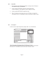
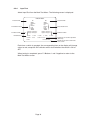
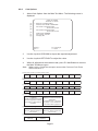
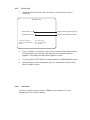
1
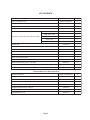
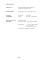
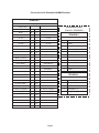
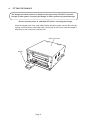
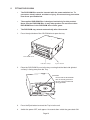
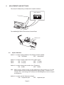
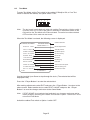
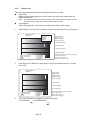
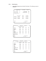
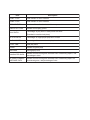
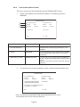
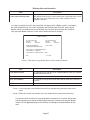
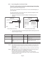
TEKKEN 5
Game PCB Kit
Connections
and
Adjustments
Part No 90500153
Issue 1
Page 2
NOTICE
is a term to describe a copyright protection technology created by
Sony Group. This
mark does not necessarily guarantee compatibily
with other products bearing the “MagicGate” trademark.
is a trademark of Sony Corporation.
est une terme décrivant une technique de protection de copyright
ne garantit pas nécessairement de
crééé par Sony Group..
cpmpatabilté avec d’autres produits portant la marque de commerce “MagicGate”
est une marque de commerce de Sony Corporation.
The DVD-ROM DISC supplied with the product must not be copied, modified,
distributed, or used for the purposes other than the operation of the product.
Copyright laws protect the contents of the DVD-ROM DISC. Infringement of
copyright laws may be subject to criminal penalties.
Do not use the supplied DVD-ROM DISC with other product models or other
media formats. Doing so may result in equipment failure.
Page 3
Contents
KIT CONTENTS ............................................................................................................................5
1.
SPECIFICATIONS .................................................................................................................7
2.
CABINET CONNECTIONS (Standard Jamma) .....................................................................7
3.
CABINET CONNECTIONS (JVS Standard) ......................................................................... 11
4.
FITTING THE DONGLE ....................................................................................................... 12
5.
FITTING THE CD-ROM ....................................................................................................... 13
6.
ADJUSTMENTS AND SETTINGS ........................................................................................ 14
6-1
Option Switches ......................................................................................................... 14
6-2
Test Mode ................................................................................................................... 15
6-2-1
Display Test .......................................................................................................... 17
6-2-2
Colour Edit ........................................................................................................... 17
6-2-3
Convergence ........................................................................................................ 17
6-2-4
Input Test .............................................................................................................. 18
6-2-5
Game Options ...................................................................................................... 19
6-2-6
Coin Options ........................................................................................................ 21
6-2-7
Sound Test ........................................................................................................... 22
6-2-8
JVS Status ........................................................................................................... 22
6-2-9
Bookkeeping ......................................................................................................... 23
6-2-10
Data Clear ............................................................................................................ 25
6-2-11
Card Options (Where Fitted) ............................................................................... 26
6-2-12
Close Setting (When Card Reader Fitted) ........................................................... 29
Page 4
KIT CONTENTS
Description
Tekken 5 PCB Rack Assy
DVD Rom CD Disc
Jamma (B) PCB
Tekken 5 Security Dongle
Rack Assy to Jamma (B) PCB connecting cables
Part No
Quantity
XTEK5-RACKASSY
1
XTEK5-DVD
1
XTEK4-JAMMA
1
XTEK5-DONGLE
1
Power Supply Loom
1
RGB Video Loom
1
RCA (Phono) Audio Loom
1
Data Loom
1
Amp EI with Flying Leaqs
69200067
1
470000574
1
Amp EI connectors with Flying Leads Loom
69200066
1
Button Decals
40000785
1 se t
Instruction Card
40000783
1
Move List Card
40000784
1
Extender PCB
Tekken 5 Promotional Poster
1
Top Flash
40000703
1
Universal Cabinet Side Decal - LHS / RHS
40000704
2
Header Decal
40000782
1
Connection and Adjustment Manual
90500153
1
XTEK5-CARDRWASSY
2
S-CONV PCB
XTEK5-SCONVPCB
2
EXCARD PCB
XTEK5-EXCARDPCB
1
EXCARD PCB to S-CONV PCB Loom
69200134
1
Read/Write Surround Decal - Player 1
40000817
1
Read/Write Surround Decal - Player 2
40000818
1
Card Decal
40000792
1
Card Read/Write Decal
40000793
1
Card Read/Write Parts (Where Applicable)
Read/Write Assembly
Page 5
1.
SPECIFICATIONS
COMPATIBILITY:
JAMMA STANDARD (with JAMMA (B) PCB)
JAMMA VIDEO STANDARD (JVS)
PCB INPUT POWER:
+5v (±5%) @ 7A (Min), +12v (±5%) @ 2A (Min)
OPERATING
ENVIRONMENT:
Temperature
Humidity
MONITOR ORIENTATION
AND SIGNAL:
Horizontal Orientation
Horizontal Frequency
RGB output level
+5ºC to +45ºC
10% to 85% (no condensation)
15kHz / 31kHz (selectable)
0.7V p-p / 3.0V p-p (selectable)
when set to 15kHz
0.7V p-p when set to 31kHz
Composite Sync / Separate Sync (selectable)
Page 6
2.
CABINET CONNECTIONS (Standard Jamma)
Option Switches
3
4
ON
OFF
Video Cable
Power Cable
Ferrite
Data Cable
Audio Cable
SYSTEM246 JAMMA(B) PC
Volume Control
Page 7
2
PCB Rack Assy
1
NO
The JAMMA (B) PCB is connected to the game cabinet with a 56way Edge Connector
(standard JAMMA) and 4 and 10way AMP EI Connectors.
JAMMA (B) PCB
JAMMA
56way
Connector
10way
AMP EI
Connector
4way
AMP EI
Connector
Note: Supplied in the Kit is an Amp EI connectors to 48way extender card adaptor
loom, for cabinets with an existing 48way connector, and an AMP EI connectors
with flying leads loom for cabinets without a 48way connection.
4 and 10way AMP EI Connector with 48way Extender Card
Part No. 69200067
4 and 10way AMP EI Connector with flying leads
Part No.69200066
Page 8
Connections for Standard JAMMA Cabinet
TEKKEN 5
Jamma 56way Edge Connector
Solder Side
Terminal No
Component Side
Connector Loom
(Part No. 69200066)
GND
A
1
GND
GND
B
2
GND
+5 volt
C
3
+5 volt
+5 volt
D
4
+5 volt
E
5
+12 volt
F
6
+12 volt
1
Polarizing Key
H
7
Polarizing Key
2
Coin Counter 2
J
8
Coin Counter 1
3
P2 Kick (Right) Sw 5
K
9
4
P2 Kick (Left) Sw 4
L Speaker (-)
L
10
L Speaker (+)
5
Audio (-) (mono)
M
11
Audio (+) (mono)
6
Video GREEN
N
12
Video RED
7
P1 Kick (Right) Sw 5
Video SYNC
P
13
Video BLUE
8
P1 Kick (Left) Sw 4
Service Switch
R
14
Video GND
9
S
15
Test Switch
10
Coin Switch 2
T
16
Coin Switch 1
P2 Start Switch
U
17
P1 Start Switch
P2 Lever UP
V
18
P1 Lever UP
P2 Lever DOWN
W
19
P1 Lever DOWN
Pin No.
P2 Lever LEFT
X
20
P1 Lever LEFT
1
P2 Lever RIGHT
Y
21
P1 Lever RIGHT
2
P2 Punch (Left) Sw 1
Z
22
P1 Punch (Left) Sw 1
3
R Speaker (+)
P2 Punch (Right) Sw 2
a
23
P1 Punch (Right) Sw 2
4
R Speaker (-)
b
24
c
25
d
26
GND
e
27
GND
GND
f
28
GND
TEKKEN 5
10way AMP EI Connector
Description
Pin No.
Page 9
GND
GND
TEKKEN 5
4way AMP EI Connector
Description
PREVIOUS TEKKEN GAMES
48way Extension Connector
Solder Side
4w AMP EI pin 4
Terminal No.
R Speaker (-)
Polarizing Key
10way AMP EI pin 4
10way AMP EI Pin 8
P2 KICK (Left)
P1 KICK (Left)
A 24
B 24
A 23
B 23
A 22
B 22
A 21
B 21
A 20
B 20
A 19
B 19
A 18
B 18
A 17
B 17
A 16
B 16
A 15
Component Side
R Speaker (+)
4way AMP EI pin 3
Polarizing Key
P2 KICK (Right)
10way AMP EI pin3
B 15
GND
10way AMP EI Pin 10
A 14
B 14
GND
10way AMP EI Pin 10
A 13
B 13
A 12
B 12
A11
B11
A 10
B 10
A9
B9
A8
B8
GND
10way AMP EI Pin 1
A7
B7
GND
10way AMP EI Pin 1
A6
B6
P1 KICK (Right )
10way AMP EI Pin 7
A5
B5
A4
B4
A3
B3
A2
B2
A1
B1
Page 10
3.
CABINET CONNECTIONS (JVS Standard)
Game PC board
Standard I/O cable
Audio cable
• Connect the red cable or the cable
indicated with "R" to the red terminal.
• Connect the white cable or the cable
indicated with "L" to the white terminal.
Video cable
• The video cable can be connected to
either connector.
If there are two video cables, connect
both cables.
C-CONV P1 harness
DC power cable
JV power supply harness
(provided with SYSTEM 256 PC Board Kit)
Page 11
4.
FITTING THE DONGLE
The dongle included in this kit is limited to this game only. DO NOT insert this
Dongle in other games. Inserting the Dongle in other games may cause damage.
Ensure that the power is switched OFF before inserting the Dongle.
Insert the dongle (with a bar code label) into the dongle insertion slot (on the left side),
making sure that the bar code label side is facing up. Insert it firmly until the dongle is
held firmly by the connector inside the slot.
Game PC board
Dongle
Page 12
5.
FITTING THE CD-ROM
•
The DVD-ROM Disc must be inserted with the power switched on. To
prevent an electric shock, accident or injury, do not touch any parts other
than those specified below.
•
The supplied DVD-ROM Disc is designed exclusively for this product.
Never use the DVD-ROM Disc in any other product. Do not insert other
DVD-ROM Discs in the DVD-ROM drive of this game.
•
The DVD-ROM tray retracts automatically after 10 seconds.
1.
Press the eject button of the CD-ROM drive to open the tray.
DVD-ROM Drive
Indicator Lamp
2.
Eject Button
Place the DVD-ROM Disc on to the tray, ensuring that the label side (printed
surface) is facing away from the Tray.
DVD-ROM
Ensure that the DVD-ROM
Disc is securely placed on
the tray, with the label side
facing upwards.
Tray
3.
Press the Eject button to retract the Tray in to the unit.
4.
Switch the power OFF, wait approx 10 seconds then switch the game back ON.
Page 13
ADJUSTMENTS AND SETTINGS
The Game PC Board Assy is fitted with 4 Option Switches.
Option Switches
2
3
NO
1
4
6.
ON
OFF
The JAMMA (B) PCB has the Volume Control fitted.
JAMMA (B) PCB
Volume Control
6-1
Option Switches
Switch 1 is used to change between Test Mode and Game Mode.
ON: Test Mode
OFF: Game Mode
Switch 2 is used to set the output level of the video signal.
31kHz
ON: 0.7V p-p
OFF: 0.7V p-p
15kHz
ON: 3.0V p-p
OFF: 0.7v P-P
Switch 3 is used to change the monitor Sync Frequency
ON: 31kHz
OFF: 15kHz
Note: When using a 31kHz monitor, set the RGB input of the monitor to 0.7v. If the
monitor does not have a setting adjustment, refer to page 17 section 6-2-1
“Display Test”, and change the Contrast and RGB Brightness levels to adjust
the brightness.
Switch 4 is used to set the Video Sync Signal
ON: Composite Sync
OFF: Seperate Sync
Page 14
Test Mode
To enter Test Mode set the Test switch in the cabinet (if fitted) to ON, or if no Test
switch is fitted to the cabinet, set Option switch 1 ON
3
4
Note:
2
NO
1
6-2
The test mode is activated only when the cabinet Test switch or Option switch 1
is moved from OFF to ON. If the game is switched on with either switch in the
ON position the Test Mode will not be activated. The switch must be switched
OFF and then ON to enter the test mode.
When the Test Mode is entered, the following screen is displayed.
SYSTEM 256 TESTMODE
S/N:000000-000000
Software serial No.
Loaded software:*****
DISPLAY TEST
Monitor Adjustments
INPUT TEST
Tests all switches
GAME OPTIONS
Set Game options
COIN OPTIONS
Set Price of Play
SOUND TEST
Sound test
JVS STATUS
Not used
BOOKKEEPING
Bookkeeping
DATA CLEAR
Data clear
CARD OPTIONS
Test and set card options
CLOSE SETTING CARD
Sets site closing time
EXIT & SAVE
Exit from test mode
Enter:
P1 -BUTTON 1
Use the Joystick Up or Down to step through the tests. (The selected test will be
displayed in red)
Press the 1 Player Button 1 to enter the selected test.
After making adjustments select EXIT and press the 1 Player Button 1 to return to the
above screen. Select another test or select ‘EXIT & SAVE’ and press the 1 Player
Button 1 to save the changes and return to the Game Mode.
Note:
If ‘EXIT &SAVE’ is not selected and activated, any changes made may not be
stored properly. Switching the cabinet Test switch or Option 1 switch OFF does
not exit the Test Mode.
Switch the cabinet Test switch or Option 1 switch OFF.
Page 15
6-2-1
Display Test
This test allows the following checks and adjustments to be made.
Colour Edit
Adjust contrast and brightness of each colour to match video output from the
PCB to the Monitor.
Note: This adjustment should only be made if the correct picture quality cannot
be achieved by using the normal monitor adjustments.
Convergence
Check and adjust the size, position and distortion of the screen image.
1.
Select display Test from the Test Menu Screen, the following screen is displayed.
DISPLAY TEST
Color bar
>Interlace
Contrast
Bright R
Bright G
Bright B
:
:
:
:
**
**
**
**
Overall contrast
Brightness (red)
Brightness (green)
Brightness (blue)
Color bar (white)
Color bar (red)
Color bar (green)
Color bar (blue)
Previous Color
EXIT color edit
NEXT
EXIT
2.
:
:
:
:
P1-Button4
P1-Button3
P1-Button1
P1-Start
Reset Colour Edit values to factory defaults
Colour Edit ON /OFF
Select next test pattern
Return to test menu screen
Each time the 1P Button 3 is pressed the Colour Edit adjustment box is turned
ON or OFF.
DISPLAY TEST
Color bar
Overall contrast
Brightness (red)
Brightness (green)
Brightness (blue)
Color bar (white)
Color bar (red)
Color bar (green)
Color bar (blue)
Previous Color
EXIT color edit
NEXT
EXIT
3.
:
:
:
:
P1-Button4
P1-Button3
P1-Button1
P1-Start
Reset Colour Edit values to factory defaults
Colour Edit ON /OFF
Select next test pattern
Return to test menu screen
Press the 1P Button 1 to step to the next test function
COLOUR BAR
CONVERGENCE
Page 16
6-2-2
6-2-3
Colour Edit
1
Ensure that the Colour Edit Adjustment Box is showing. (Press P1 Button 3
if the Adjustment box is not displayed.
2.
Use the Joystick UP/DOWN to step to the required adjustment.
(Contrast, Brightness (red), Brightness (green), Brightness (blue)).
3.
Use the Joystick LEFT/RIGHT to adjust the value.
3.
When all adjustments have been made, press P1 Button 1 to step to the
Convergence Test or P1 Start Button to return to the Main Test Menu screen
Convergence
Use this screen to adjust the geometry (height, width , etc.) of the Monitor.
D I S P L AY T E S T
Convergence
Previous Color
EXIT color edit
NEXT
EXIT
Interlace
Contrast
Bright R
Bright G
Bright B
:
:
:
:
:
:
:
:
150
100
100
100
P1-Button4
P1-Button3
P1-Button1
P1-Start
The screen colour will change each time P1 Button 4 is pressed.
When all adjustments have been made, press P1 Button 1 to return to the Colour
Bar Screen or P1 Start Button to return to the Main Test Menu screen.
Page 17
6-2-4
Input Test
Select Input Test from the Main Test Menu. The following screen is displayed.
INPUT TEST
P1 Start switch
1P
Start
Service
Up
Down
Left
Right
TEST
2P
Start
Service
Up
Down
Left
Right
TEST
Button 1 Button 2
Button 3 Button 4
: :
: :
Button 1 Button 2
Button 3 Button 4
: :
: :
P1 8-direction lever
P1 Button switch
DIP switches
DIPsw 1 : OFF
COIN 1: 0 0 0
2 : OFF
3 : OFF
COIN 2: 0 0 0
EXIT :
P2 Start switch
P2 8-direction lever
P2 Button switch
4 : OFF
P1-Button1&2
Number of coin counter operations
(default: 0)
Shows how to return to test mode
menu screen
Each time a switch is operated, the corresponding item on the display will change
colour to red, except the DIP switches which show whether the switch is ON or
OFF.
When testing is completed, press P1 Buttons 1 and 2 together to return to the
Main Test Menu screen.
Page 18
6-2-5
Game Options
1.
Select Game Options from the Main Test Menu. The following screen is
displayed.
GAME OPTIONS
< Defaults in Green >
(a)
(b)
(c)
(d)
(e)
(f)
(g)
(h)
(i)
(j)
> Difficulty level: HARD
Fight count <1P game> : 2
Fight count <VS game> : 2
Life bar <1P game> : +1
Life bar <VS game> : +1
Guard damage: OFF
Neutral guard: ON
Round time: 60
Character change at continue: YES
Character change at VS game: YES
Downward
Modify :
EXIT :
P1-Left/Right
P1-Start
GAME OPTIONS
< Defaults in Green >
(d)
(e)
(f)
(g)
(h)
(i)
(j)
(k)
(l)
(m)
(n)
Upward
Life bar<1P game>:+1
Life bar<VS game>:+1
Guard damage:OFF
Neutral guard:ON
Round time:60
Chararacter change at continue:YES
Character change at VS game:YES
Sound in attract mode:YES
Event mode: OFF
Hit color: GREEN
> Attract Movie: ON
Modify :
EXIT :
P1-Left/Right
P1-Start
2.
Use the Joystick UP/DOWN to step to the required adjustment.
3.
Use the Joystick LEFT/RIGHT to adjust the value.
4.
When all adjustments have been made, press P1 Start Button to return to
the Main Test Menu screen
Page 19
(a) Difficulty level (degree of game difficulty)
EASY
MEDIUM
HARD
VERY HARD
ULTRA HARD
(b) Fight Count <1P game > (number of rounds required to win the game in 1 player mode)
1
2
3
4
5
(c)) Fight Count <VS game > (number of rounds required to win the game in 2 player mode)
1
2
3
4
5
(d) Life bar <1P game > (energy guage in 1 player mode)
-2
-1
NORMAL
+1
+2
(e) Life bar < VZ game > (energy guage in 2 player mode)
-2
-1
NORMAL
+1
+2
(f) Guard damage (damage received on guard)
ON (
OFF
(g) Neutral guard ( guard activated with lever in neutral)
ON
OFF
(h) Round time (time [seconds] per round)
30
40
60
80
99
(i) Character change at continue (change of character for continued game)
YES (possible)
NO (not possible)
(j) Character change at VS game (change of character when another player joins in) see note
YES (possible)
NO (not possible)
(k) Sound in attract mode
YES (with sound)
NO (without sound)
(l) Event mode (action after 2 player game has finished)
ON
OFF
(m) Hit colour (colour of graphic effects when attacks are successful
RED
YELLOW
(n) Attract Movie (movie shown in attract mode)
OFF
ON
Note: When card is used, the game character cannot be changed even if the setting (j) has been set to YES.
Page 20
6-2-6
Coin Options
1.
Select Coin Options from the Main Test Menu. The following screen is
displayed.
:
COIN OPTIONS
Defaults in Green
> Start cost: 1Credit to START
Continue cost: 1Credit to CONTINUE
Coin chute 1 mechanical value:
1Coin count as 1coin
Coin chute 2 mechanical value:
1Coin count as 1coin
Credit mode: COMMON
Coin counter: 1counter
Free play: NO
(a)
(b)
(c)
(d)
(e)
(f)
(g)
Modify :
EXIT :
P1-Left/Right
P1-Start
2.
Use the Joystick UP/DOWN to step to the required adjustment.
3.
Use the Joystick LEFT/RIGHT to adjust the value.
4.
When all adjustments have been made, press P1 Start Button to return to
the Main Test Menu screen
Note: When using a CashFlow acceptor ensure that Cost and Coin Chute
values are set to 1
(a) Star t cost (number of credits to star t a game)
1
2
3
4
5
6
7
8
9
(b) Continue cost (number of credits to continue a game - must be equal to or smaller than star t
cost)
1
2
3
4
5
6
7
8
9
7
8
9
7
8
9
(c) Coin chute 1 mechanical value (number of credits for each coin)
1
2
3
4
5
6
(d) Coin chute 2 mechanical value (number of credits for each coin)
1
2
3
4
5
6
(e) Credit Mode (credit storage and use)
COMMON
Credits are stored as a single
account regardles of which
coin switch or star t switch is
operated.
EACH ONE
Different credit accounts are
established.
Credits from coin 1 are used
by player 1 and credits from
coin 2 are used by player 2
(f) Coin counter (assignment of coin meters)
1 COUNTER
Both coin switches share one
coin counter
2 COUNTERS
Each coin switch has its own
coin counter
(g) Free play
YES (no coins
required)
NO (coins
required)
Page 21
6-2-7
Sound Test
1.
Select Sound Test from the Main Test Menu. The following screen is
displayed.
SOUND TEST
POSITION:off
Displays which speaker is playing
SPEAKER:stereo
Displays monaural/stereo setting
Check Sound
Change Speaker
EXIT
6-2-8
: P1-Button1
: P1-Left/Right
: P1-Start
2.
Press 1P Button 1 to conduct a stereo check. Sound will be produced from
the left speaker only, then the right speaker only, then both speakers
together. The display will show which speaker is active.
3.
Use the Joystick LEFT/RIGHT to change between STEREO/MONO sound.
4.
When testing has been completed, press P1 Start Button to return to the
Main Test Menu screen
JVS Status
This test is inactive and not used on JAMMA system cabinets, it is only
operational on JVS system cabinets.
6-2-9
Bookkeeping
1.
Select Bookkeeping from the Main Test Menu. The following screen is
displayed.
Bookkeeping
Coin 1 Total
Coin 2 Total
Service Total
Freeplay Total
1P
1P
VS
All
Play
Cont.
Play
Play
ON TIME
0
0
0
1
Play Ratio
1P Play Ratio
VS Play Ratio
Total Time
0:00:00
0:00:00
0:00:00
0:00:00
Count
000
000
000
000
Next:
Exit :
Bookkeeping
0%
0%
0%
Average
0:00:00
0:00:00
0:00:00
0:00:00
P1-Button1
P1-Start
ON TIME
0:00:00
CHARACTER DATA
Rate
Total
Raven
0%/
0 /
FENG
0%/
0 /
ASUKA
0%/
0 /
PAUL
0%/
0 /
JIN
0%/
0 /
LAM
0%/
0 /
KING
0%/
0 /
YOSHIMITSU
0%/
0 /
NINA
0%/
0 /
HWOARANG
0%/
0 /
Downward
Next:
Exit :
Bookkeeping
0:00:00
1P
0 /
0 /
0 /
0 /
0 /
0 /
0 /
0 /
0 /
0 /
VS
0
0
0
0
0
0
0
0
0
0
P1-Button1
P1-Start
ON TIME
0:00:00
VS GAME WINNING AVERAGE DATA
WinAve
Total
Win
LoseVS
Raven
0%/
0 /
0 /
0
FENG
0%/
0 /
0 /
0
ASUKA
0%/
0 /
0 /
0
PAUL
0%/
0 /
0 /
0
JIN
0%/
0 /
0 /
0
LAM
0%/
0 /
0 /
0
KING
0%/
0 /
0 /
0
YOSHIMITSU
0%/
0 /
0 /
0
NINA
0%/
0 /
0 /
0
HWOARANG
0%/
0 /
0 /
0
Downward
Next:
Exit :
P1-Button1
P1-Start
Item
Description
COIN1 TOTAL
Total number of coins inserted
COIN2 TOTAL
Total number of coins inserted
SERVICE TOTAL
Number of times the Service switch was pressed
FREEPLAY TOTAL
Number of free play games
Percentage of play hours in total power ON hours
PLAY RATIO
(Rounded to one decimal place)
1P PLAY RATIO
Percentage of single player play hours in total
VS PLAY RATIO
Percentage of tournament mode play hours in total
TOTAL TIME
Total play hours
COUNT
Number of game plays
AVERAGE
Average play time
CHARACTER DATA
Number of times each game character was selected by players, and
percentage in total
VS GAME WINNING
AVERAGE DATA
Number of times each game character was selected by players for
tournament game, and percentage of wins
6-2-10
1.
Data Clear
Select Data Clear from the Main Test Menu. The following screen is
displayed.
DATA CLEAR
(a)
(b)
(c)
(d)
(e)
(f)
(g)
Cancel
Bookkeeping clear
Ranking data clear
FlashROM data clear
Set defaults all options
Initialization of the card data for recovery
All clear
CLEAR:
Exit:
P1-Button1
P1-Start
2.
Use the Joystick UP/DOWN to step to the required adjustment.
3.
When all adjustments have been made, press P1 Start Button to return to
the Main Test Menu screen
(a)
(b)
Returns to the Main Test Menu.
Resets all Book Keeping data to zero
(c)
(d)
Resets all ranking data such as record of consecutive wins to factory default
Initializes the data stored in the flash memory, such as ghost data and replay
(e)
data.
Resets all Game and Coin Options to factory default.
(f)
(g)
Deletes the information for the card data restoration.
Returns ALL data and settings to defaults.
6-2-11
Card Options (Where Fitted)
This test is used to set the Read/Write unit and TEKKEN-NET IDcard.
1.
Select Card Options from the Main Test Menu. The following screen is
displayed.
CARD OPTIONS
(a)
P1 card R/W found
(b)
Sensor
(c)
Solenoid
:
:
P2 card R/W found
OFF
Sensor
UNLOCK
Solenoid
Insert CARD
OFF
:
UNLOCK
Insert CARD
Exit:
Item
:
P1 - Start
Options
Description
(a) P1 card R/W found
(P2 card R/W found)
[found] or [not found]
Displays [found] if the card R/W unit is connected to the
Game PC board, and displays [not found] if it is not
connected.
(b) Sensor
[ON] or [OFF]
Displays [ON] when a card is inserted in the card R/W
unit, and displays [OFF] when there is no card in the
card R/W unit
(c) [UNLOCK] or [ LOCK]
[UNLOCK] or [LOCK]
As soon as the card is inserted into the card R/W unit,
the card is locked into position and the screen displays
"LOCK".
If the card is not locked in position, the screen displays
"UNLOCK"
2.
To conduct a test or data restoration, insert a card into the Read/Write unit
CARD OPTIONS
P1 card R/W found
Sensor
:
OFF
Solenoid
: UNLOCK
P2 card R/W found
Sensor
: OFF
Solenoid
: UNLOCK
cardNo 0000 0000 0000 0000
cardNo 0000 0000 0000 0000
Insert CARD
Press Button 1 to WRITE/READ TEST
Press Button 2 to REJECT
Exit:
P1 - Start
* Note: The above is an example of the screen display when two cards
are inserted into the P10-side card R/W unit
Page 26
Display after card insertion
Item
Description
CardNo 0000 0000 0000 0000
CardNo 0000 0000 0000 0000
When a card is inserted in the card R/W unit, the 16-digit number (access
code) printed on the reverse of the inserted card is displayed on the screen.
When two cards are inserted, the access codes for both cards are
displayed in two rows
If a card is inserted in the P1-side card R/W unit, press the P1 Button switch 1 to conduct
the card read/write test. If a card is inserted in the P2-Side card R/W unit, press the P2
Button switch1 to conduct the card read/write test. To eject the card from the card R/W
unit, press the Button switch 2 on the side in which the card is inserted.
CARD OPTIONS
P1 card R/W found
Sensor
:
OFF
Solenoid
: UNLOCK
P2 card R/W found
Sensor
: OFF
Solenoid
: UNLOCK
READ DATA ERROR
cardNo 0000 0000 0000 0000
Insert CARD
Press Button 1 to WRITE/READ test
Press Button 2 to REJECT
Press Button 3 to Restore Data *Note 1
Exit:
P1 - Start
* Note 1: This item is only shown when an error card is inserted
Item
Description
CARD READ ERROR
This indicates that a card other than a TEKKEN-NET ID card was inserted
and data could not be read.
CARD WRITE ERROR
This indicates that the Write test has failed.
READ DATA ERROR
This indicates that comparison of the data after the write test resulted in a
mismatch.
WRITE READ OK
This indicates that both read and write operations were successful.
* Note 1: Conducting the card read/write test will not damage the game play data on the
card.
* Note 2: When two cards are inserted, the card read/write test cannot be performed.
If a card on which a write error was generated is inserted or if a card on which data
was destroyed due to power-off during data writing is inserted, pressing the Button
switch 3 of the applicable player side initiates an attempt to restore the data on the
card.
Page 27
Card data may or may not be restored depending on the condition of the card, as
described below.
•
•
•
•
•
•
•
Data may only restored with the card that was used to play the game with the
Game PC board that you are working on and has been set to the test mode. It
should be noted that there is a limit to the amount of data saved (10 cases max.).
If a write error was indicated during a game play, it may be possible to restore the
data successfully.
If power interruption ocured when data was being written to the card, it may be
possible to restore the data successfully.
If the card was pulled out during a game play, the data cannot be restored.
Data restoration can be tried only once for one error.
Data restoration cannot be conducted with a card whose access code is different
from the data stored in the cabinet.
Data cannot be restored with a card which disallows data reading or writing due
to damage.
To return to the test menu screen, press P1 Start switch.
Page 28
6-2-12
Close Setting (When Card Reader Fitted)
This mode is used to set the site closing time, and prevents the card from being
used from 15 minutes before the set time. This ensures that data is not lost if the
game is powered-down during game play.
The time can be set between 19:00 and 31:00 (7:00 am on the following day), or
24 hour operation.
The same closing time can be set for every day, or the the closing time can be
set differently for each day of the week.
1.
Select Close Setting from the Main Test Menu. The following screen is
displayed.
CLOSE SETTING
Defaults in Green
CLOSE SETTING
Defaults in Green
>Time Setting:2004/10/04 (MON) 19:00
(a)
Schedule type : DAY
(b)
(c)
Hours : 24
Minutes : 24
Modify:
Exit:
(d)
P1-Left / Right
P1 - Start
Item
(SUN)
(MON)
(TUE)
(WED)
(THU)
(FRI)
(SAT)
Hours:24
Hours:24
Hours:24
Hours:24
Hours:24
Hours:24
Hours:24
(SUN) Minutes:00
(MON) Minutes:00
(TUE) Minutes:00
(WED) Minutes:00
(THU) Minutes:00
(FRI) Minutes:00
(SAT) Minutes:00
Modify:
Exit:
(a)
(b)
(c)
(d)
P1-Left / Right
P1 - Start
Close Setting screen (Week)
Close Setting screen (Day)
2.
>Time Setting:2004/10/04 (MON) 19:00
Schedule type : WEEK
Use the joystick Up/Down to scroll through the options and the joystick Left/
Right to change the settings.
Setting Options
Default
(a) TIME SETTING
Description
Set the current time
(b) SCHEDULE TYPE
[DAY]<=>[WEEK]
[DAY]
(c) HOURS
[24]=>[25]=>[26]=>[27]=>[28]=>29]=>[30]=>[31]
[ALLDAY]=>[19]=>[20]=>[21]=>[22]=>[23]=>[24]
(d) MINUTES
[00]=>[15]=>[30]=>[45]=>[008]=>....
Select daily setting [DAY] or weekly setting
[WEEK]. *note1
[ALLDAY] Set the [HOURS] for closing time setting.
Select [ALLDAY] if the machine is made
available 24 hours of the day.
[24HOURS] Select [MINUTES] for closing time *note 2
*Note 1: When [DAY] is selected, the same closing time applies to every day of the
week, and the machine disallows the use of card 15 minutes before the set
closing time.
The machine begins accepting cards from 7:00am, except when [ALL DAY]
is set.
*Note 2: When [HOURS] is set to [30], the [MINUTES] indication becomes fixed at
[00]. When [ALL DAY] is set, “(24 HOURS)” is indicated.
Example: When [HOURS] and [MINUTES] are set to [25] and [30],
respectively, the daily closing time will be 1:30am, and the machine will stop
accepting cards at 1:15am.
Page 29
Select “Time Setting” and press the P1 Button switch to display the time setting screen
shown below.
CLOSE SETTING(CARD)
Defaults in Green
Now
2004 /10 / 04 (MON)
>Year
Month
Day
Hour
Minute
:
:
:
:
:
19:00:00
(a)
(b)
(c)
(d)
(e)
2004
10
04
19
00
Modify:
Exit:
P1-Left / Right
P1 - Start
Close Setting screen (Time Setting)
Item
Setting Options
(a) YEAR
Set the current Year.
(b) MONTH
Set the current Month.
(c) DAY
Set the current Day. (Sunday is Day 01)
(d) HOURS
Set the Hours of the current time.
(e) MINUTES
Set the Minutes of the crrent time.
*
Note:The day of the week is automatically displayed when the [DAY] setting is entered.
To return to the test menu screen, press the P1 Start switch.
Page 30
Page 31
Copies of Namco Game Manuals can be downloaded from our website:
www.namco.co.uk
They are located under Components, Sales and Service
For all Parts or Technical Support contact:
Brent Electronic,
Namco House,
Units 5-8, Acton Park Estate,
The Vale,
London. W3 7QE
www.brentelectronic.co.uk
For Technical Support, Warranty and
Advance Replacement Parts:-
+44 (0) 20 8324 6120
For Consumable Parts:-
+44 (0) 20 8324 6102
Fax for both:-
+44 (0) 20 8324 6126
Page 32