1
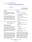
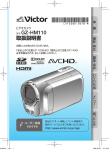
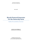
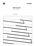
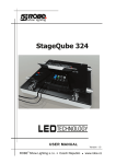
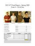
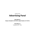
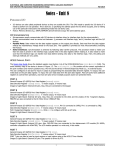
EEL 4924 Electrical Engineering Design (Senior Design) Final Report 23 April 2013 Project Name: Run-Away Alarm Clock Team Members: Name: Michael Frye Name: Daniel Powell Project Abstract: Our project consists of an alarm clock that begins to drive itself around in order to make the owner get out of bed and chase it to wake up. The clock will begin to drive around under two scenarios: in the case that the alarm goes off after the snooze button has been pressed, or if the alarm has been going off for more than fifteen seconds. In addition, the alarm clock has the option to be controlled by a handheld remote control, which allows the user to play with the device as a type of remote control car. The robotic alarm clock has sensors which allow it to know when it is coming too close to a wall or other object, so it can turn another direction. In addition to the time, the alarm clock also allows the user to view the date and indoor temperature with the simple push of a button. The alarm clock contains a microcontroller that processes the time and date, temperature sensor, and remote control data, and produces pulse-widthmodulated signals for the motor drivers. All of the time, data, and temperature data is displayed on an LCD screen on the front of the alarm clock. University of Florida EEL 4924—Spring 2013 22-Apr-13 Electrical & Computer Engineering Page 2/27 Final Report: Run-Away Alarm Clock Table of Contents Project Abstract: .................................................................................................................................... 1 Project Features ..................................................................................................................................... 3 Project Objectives .................................................................................................................................. 4 Analysis of Competitive Projects ........................................................................................................... 8 Concept Selection ................................................................................................................................ 10 Technology Selection ........................................................................................................................... 12 Project Architecture ............................................................................................................................. 16 Flowcharts ........................................................................................................................................... 18 Division of Labor ................................................................................................................................. 22 User Manual ........................................................................................................................................ 23 Bill of Materials ................................................................................................................................... 25 Gantt Chart .......................................................................................................................................... 27 List of Figures Figure 1 - Flowchart for modes of operation .......................................................................................... 6 Figure 2 - Clocky ................................................................................................................................... 8 Figure 3 - Flying Alarm Clock ............................................................................................................... 9 Figure 4 - Simplified H-bridge design showing only two control input ................................................. 14 Figure 5- System Block Diagram ......................................................................................................... 16 Figure 6 - Simplified Software Flowchart ............................................................................................ 20 Figure 7 - Simplified Interrupt Software Flowcharts ............................................................................. 21 Figure 8 –Gantt Chart .......................................................................................................................... 27 List of Tables Table 1- Control logic for H-bridge ...................................................................................................... 14 Table 2 - Division of Labor .................................................................................................................. 22 Table 3 - Bill of Materials .................................................................................................................... 25 University of Florida EEL 4924—Spring 2013 22-Apr-13 Electrical & Computer Engineering Final Report: Run-Away Alarm Clock Page 3/27 Project Features This project is being designed for the needs of students and professionals who struggle to wake up in the morning. The goal of this project is to create an alarm clock that can autonomously drive around on a random track in order to force the owner to get out of bed and chase it. Features of the project include: Time, date, alarm time, and temperature information on LCD display. o Time can be displayed in either 12-hour or 24-hour format. Selectable by user. o Date information includes day of the week, month, date, and year. o Alarm time will be displayed in the same hour format as the time. o Temperature can be displayed in either Celsius or Fahrenheit. Selectable by user. Alarm clock function with snooze feature. Three operating modes, switchable by the user: o Wheels Off (Alarm On): The robot will function as a normal alarm clock, without driving around when the alarm goes off for more than fifteen seconds or if the snooze button has already been pressed. o Autonomous (Alarm On): The robot will drive in a random path as the alarm goes off, forcing the user to get out of bed and turn the alarm off. o Remote Control (Alarm Off): The robot will operate as a remote control car for use as a toy with the handheld controller provided. The alarm will be disabled when the robot is in Remote Control mode. Able to withstand driving off of a reasonably high ledge, such as a nightstand or table. Rechargeable battery circuit for long-term use of both the alarm clock and remote controller. University of Florida EEL 4924—Spring 2013 22-Apr-13 Electrical & Computer Engineering Final Report: Run-Away Alarm Clock Page 4/27 Project Objectives The main objective of our project was to design a system that can operate both autonomously and in a remote-controlled manner. As a whole, the project meets the following objectives: LCD Display Objectives o Either the current time or various functions can be displayed on the LCD, which is selectable by the user. The functions include the day of the week, date, temperature, and alarm time. o The current time will be accurately displayed in either 12-hour or 24-hour format, which is selectable by the user. When using the 12-hour format, the display will indicate whether the time is AM or PM. o The day of the week and date will be displayed. The date format will be MM/DD/YY. Shorter months and leap years will be taken into account for the date. o Indoor temperature will be displayed in either Celsius or Fahrenheit, which is selectable by the user. o Interactive clock time set with push buttons will be displayed. The user can see in live time as they set the time, date, and day of the week. o Interactive alarm time set with push buttons will be displayed. The user can see in live time as they set the alarm time. Device Operation Objectives o The robot uses two independently controlled motors with large wheels (one on each side), allowing for zero radius turning. Motors and wheels are aligned with the central axis of the robot to ensure balance and eliminate the need for a caster wheel. Motors and wheels are mounted to provide sufficient shock absorption so the robot can drop from a reasonable height (~3-5 feet) without being damaged. University of Florida EEL 4924—Spring 2013 22-Apr-13 Electrical & Computer Engineering Final Report: Run-Away Alarm Clock Page 5/27 Each motor is controlled by its own motor driver (H-bridge), which we designed and built. The motor drivers are controlled via pulse width modulation (PWM) signals from the microcontroller, with a +6V NiMH battery supplying the current for the motors. o The robot has three switch-selectable operating modes, Wheels Off mode, Autonomous mode, and Remote Control mode. In Wheels Off mode, the robot functions only as an alarm clock. All driving features are disabled. In Autonomous mode, the robot begins to drive itself around after the alarm has been going off for over fifteen seconds or if the alarm goes off a second time after the snooze button has been pressed. The robot first drives forward a short distance (in order to drive off a ledge or nightstand), then begins driving in a random path while avoiding any walls or obstacles. Obstacle detection is accomplished via analog IR sensors that are mounted on the front and rear of the robot. When an obstacle is detected, the robot will either turn or reverse its direction to avoid running into the obstacle. The alarm will continue to sound until the user manually turns off the alarm; however, the alarm sound will switch from a chime to a beeper when the alarm is driving. The wheels will turn off when both the alarm and autonomous modes are disabled. In Remote Control mode, the robot functions as a remote control toy. Alarm functions and obstacle detection are disabled in remote control mode, giving the user full control of the robot. A handheld remote controller is used to communicate with the robot through an XBee wireless device. University of Florida EEL 4924—Spring 2013 22-Apr-13 Electrical & Computer Engineering Final Report: Run-Away Alarm Clock Page 6/27 Figure 1 - Flowchart for modes of operation Audio Objectives o An alarm tone is stored in memory and is sent to a digital-to-analog converter (DAC) via the serial peripheral interface (SPI) in the microcontroller. The output from the DAC is filtered and amplified to drive one speaker mounted in the housing of the robot. The user is able to adjust the alarm volume with a potentiometer mounted on the housing. o The alarm has two different tones that are played. When the clock is not driving, either before the 15 seconds have gone off for autonomous mode or in wheels off mode, the alarm sound is a chime. When the alarm clock begins driving, the alarm song switches to a beeper. Power Objectives o The robot is powered by a 6V rechargeable NiMH battery. The battery is capable of providing power to the motors for at least 20 minutes of continuous driving operation. Power for the microcontroller and other electronics is regulated to +3.3V. Additional +5V regulation is used for the IR sensors, bandpass filter, and audio amplifier circuit. University of Florida EEL 4924—Spring 2013 22-Apr-13 Electrical & Computer Engineering Final Report: Run-Away Alarm Clock Page 7/27 Housing Objectives o The cylindrical housing for the robot is constructed from clear 3” diameter PETG tubing. It is light and strong enough to withstand falling, and large enough to securely contain all electronics. The hardware for mounting the motors, shock absorbers, and wheels is attached to two removable PVC endcaps. Holes are cut out for the IR sensors, the back panel, and the LCD. o The back panel on the alarm clock includes switches, push buttons, and a volume knob. Switches are used for mode selection (autonomous, remote control, wheels off), display selection (time or function), hour format, temperature format, and alarm on/off. Push buttons are used for clock time set, alarm time set, clock/alarm time increment, and snooze. A knob is used for volume control of the speaker. Each of the components is labeled for simplicity of use. o The LCD cutout is lined with a foam gasket which protects the LCD from shock due to falling or other rough contact. o Two metal counterweights are mounted on the bottom interior of the housing for balance and driving stability. The design of the robot makes it a type of pendulum, so weight must be concentrated in the bottom to reduce and/or prevent uncontrolled rotation of the housing. University of Florida EEL 4924—Spring 2013 22-Apr-13 Electrical & Computer Engineering Page 8/27 Final Report: Run-Away Alarm Clock Analysis of Competitive Projects Similar products on the market today include Clocky and the Flying Alarm Clock. Both of these products require the owner to get out of bed and perform some type of action before the alarm sound will end. The Run-Away Alarm Clock is more similar to Clocky than it is the Flying Alarm Clock. Clocky is a commercial alarm clock that drives off the owner's nightstand and around on the floor in order to get the owner out of bed. The clock does not begin driving unless the snooze button has been pressed. Once the snooze button has been pressed, the clock waits one minute and then begins driving. The alarm clock will not begin driving in the event that the alarm has been going off for a long time. Clocky allows for the selection between wheels off and autonomous mode. In wheels off mode, the clock functions as a standard alarm clock with snooze feature. Clocky also allows for the selection between 12-hour and 24-hour format. Figure 2 - Clocky The Run-Away Alarm Clock includes all of the features of Clocky and many more. On top of the displayable features of Clocky, the Run-Away Alarm Clock adds day of the week and date information, temperature in either Celsius or Fahrenheit, and the alarm time. As far as the autonomous feature goes, University of Florida EEL 4924—Spring 2013 22-Apr-13 Electrical & Computer Engineering Page 9/27 Final Report: Run-Away Alarm Clock the Run-Away Alarm Clock begins driving if the snooze button has already been pressed and the alarm resounds after a minute, just like Clocky. In addition, the Run-Away Alarm Clock begins driving autonomously after the alarm has been sounding for 15 seconds. This requires the owner to get out of bed in the event that they do not hear the alarm. Finally, the Run-Away Alarm Clock adds a remote control feature allowing the alarm clock to be used as a toy car. A handheld controller is included to operate the robot. The Flying Alarm Clock shoots off a rotor with a propeller that falls to a random location when the alarm goes off. The alarm will continue sounding until the owner gets out of bed, finds the rotor, and places it back on top of the alarm clock. This product is similar to the Run-Away Alarm Clock in that they both require the owner to get out of bed and perform a function in order to disable the alarm; however, the functions performed by this alarm clock are far different than those by the Run-Away Alarm Clock. Figure 3 - Flying Alarm Clock University of Florida EEL 4924—Spring 2013 22-Apr-13 Electrical & Computer Engineering Page 10/27 Final Report: Run-Away Alarm Clock Concept Selection We chose to implement our design in the manner we are because we found it to be the most logical way to do so at an affordable price. We designed our project around the idea that this could potentially become a commercial project. If the Run-Away Alarm Clock were sold on the market, shoppers would not want to pay an absurd price for an alarm clock. For this reason, we designed our alarm clock with cost in mind, estimating what a typical price would be for a product like ours. When forming ideas for what to include in our project, we started at the commercial product Clocky. Clocky performs the basic functions of displaying the time and allowing an alarm to be set. It surpasses the features of a standard alarm clock by driving around a minute after the snooze button has been pressed. We decided that our project needed to include those features as a minimum, but in order to compete commercially with a product like Clocky we decided to add additional attributes. As additional attributes, we decided to add day of the week and date to the display. Clocky does not include this information on its display, but we felt it was a vital feature of many higher scale alarm clocks such as the iHome. Next, we chose to add temperature to the display since many owners do not want to have to check their thermostat in order to determine the indoor temperature. We allow the user to select between Celsius and Fahrenheit in case the owner has a preference. Since the motors will require a lot of power, we chose to add a recharge circuit for the battery. This prevents the Run-Away Alarm Clock from consuming lots of conventional batteries once the product has been purchased, thus leading to fewer after-market costs. A very important addition is the Run-Away Alarm Clock will begin driving autonomously in the event that the alarm has been going off for more than fifteen seconds. This was added so that the owner would not be able to sleep through the alarm. Finally, we added a remote control option to provide a fun feature for younger owners. The Run-Away Alarm Clock is able to function as a remote control car with a handheld remote control. We chose to make the Run-Away Alarm Clock move in a random path when operating autonomously. The reasoning behind this is that the owner could memorize the path that the alarm clock University of Florida EEL 4924—Spring 2013 22-Apr-13 Electrical & Computer Engineering Page 11/27 Final Report: Run-Away Alarm Clock will take if it starts at the same spot every morning. With a random path, the owner will have to get out of bed and consciously chase after the alarm clock to catch it, rather than mindlessly following a memorized path. Another feature we considered adding was auxiliary input so the alarm could play songs from the owner's MP3 player. We decided against the auxiliary input because it would put the owner's MP3 player in risk of damage when the alarm clock began driving around. Also, it would require a cord on the device. The Run-Away Alarm Clock needs to be cordless because cords could get caught on something and cause damage to the electronics or nearby objects. University of Florida EEL 4924—Spring 2013 22-Apr-13 Electrical & Computer Engineering Page 12/27 Final Report: Run-Away Alarm Clock Technology Selection As previously stated, we designed the Run-Away Alarm Clock with cost in mind, seeing how this could become a commercial product and consumers would not want to pay a ridiculous price for the product. Therefore, when selecting components for the project, we tried to find those that could provide the most features at the lowest cost. In other words, we created a performance-to-cost ratio and chose those components that had the highest ratio. One of the most important components of the project is the microcontroller. The microcontroller will be used to process all of the input data and generate outputs based on that data. When selecting the microcontroller, the needs of all the other components of the project were taken into account. With the project being an alarm clock, we started our technology search with a clock chip. We found the Microchip MCP7940M, which is a real-time clock and calendar (RTCC) chip. The chip communicates with a microcontroller through I 2C and has the option of running on a 32.768 kHz external crystal for time precision. The RTCC chip provides the time in both 12-hour and 24-hour format. In addition, it sends the day of the week and the date to the microcontroller. Another important aspect of the chip is that it offers two alarms to be controlled by the microcontroller. From this chip, we knew that the microcontroller used would require an I 2C. Next, we looked at analog temperature sensors in order to determine which would provide a desired temperature ranged at a reasonable cost. The AD22100STZ provides an analog voltage in a usercontrolled voltage range that can be connected to an A/D input on a microcontroller. Based on this analog input, the Celsius or Fahrenheit temperature can be calculated using a simple transfer function. Using this temperature sensor requires an A/D converter on the microcontroller. For the audio portion of the alarm clock, we planned to use a serial DAC connected to an analog filter/amplifier. To interface with the DAC, we knew we would need an available SPI module on the microcontroller. The other audio hardware would be analog and independent of the microcontroller. University of Florida EEL 4924—Spring 2013 22-Apr-13 Electrical & Computer Engineering Page 13/27 Final Report: Run-Away Alarm Clock All of the time, date, and temperature information are displayed on an LCD on the front of the alarm clock. When looking for an LCD, we wanted one that would provide characters large enough to let the owner see the display from across a room. Also, we wanted an LCD that would provide a backlight, allowing the time to be visible in the dark. We chose to use a 20x4 LCD display made by CrystalFontz, because they offer high quality LCDs at prices more reasonable than other vendors. Also, both team members were familiar with CrystalFontz LCDs from previous courses. A 20x4 LCD allows characters to stand four rows high, making them perfectly visible to the owner. The LCD interacts with the microcontroller through I/O pins on the device. The LCD we chose would require 6 I/O pins on the microcontroller to operate it in 4-bit mode and 10 I/O pins if we would have used the 8-bit mode. After we considered all of the needs for the alarm clock portion of the robot, we looked into necessary functions for driving operation. We calculated that two motors with a no-load speed in the range of 200-400 rpm would provide desired driving speeds once they were loaded and tuned to the right frequency/duty cycle. We were able to find several good options for motors in this speed range, and the motors with the best performance-to-cost ratio were primarily 6-volt motors. We decided to use 6 V motors, which told us that we would need a 6 V power source, preferably rechargeable, and motor drivers to supply the motor current. To be more efficient, the motor drivers will be controlled via PWM, so we wanted our microcontroller to have built-in PWM capabilities. We decided that four PWM channels (two per motor driver) would be sufficient, since our motors would only need go forward, reverse, or coast to a stop (no braking). Figure 4 and Table 1 show our simplified scheme for the motor drivers and PWM control logic. University of Florida EEL 4924—Spring 2013 22-Apr-13 Electrical & Computer Engineering Final Report: Run-Away Alarm Clock Page 14/27 +6 V Q1 Q2 M Q2 Q1 GND Figure 4 - Simplified H-bridge design showing only two control input Table 1- Control logic for H-bridge Q1 Q2 DIRECTION ON OFF FWD OFF ON REV OFF OFF STOP (COAST) ON ON NEVER USE (DAMAGE!) For obstacle detection, we planned to use analog infrared (IR) sensors in the front and back of the robot. This required two outputs and two more A/D inputs to measure when an obstacle is within a certain distance of the robot. We chose our microcontroller to meet all of the needs the other components of the project. We began our microcontroller search with Microchip because both partners were familiar with the PIC18 microcontroller used in Junior Design. Unfortunately, none of the PIC18 family of microcontrollers provided enough PWM channels for our design, so we looked at the bigger PIC24 family. The PIC24EP256MC206 microcontroller meets all of the needs of our design and has many additional University of Florida EEL 4924—Spring 2013 22-Apr-13 Electrical & Computer Engineering Page 15/27 Final Report: Run-Away Alarm Clock features on top of that. It offers up to 53 I/O pins, which definitely came in handy, since our project is very I/O dependent. I/O pins were used for many buttons and switches in order to select different features of the project, i.e. Celsius/Fahrenheit, time/date/temp on LCD display, setting alarm time. This microcontroller is also very affordable, which allows us to keep the total project design at a reasonable cost. Figure 5, in Project Architecture, shows the overall system diagram for our project, which accounts for all of the features we considered in the preliminary planning of our project. University of Florida EEL 4924—Spring 2013 22-Apr-13 Electrical & Computer Engineering Page 16/27 Final Report: Run-Away Alarm Clock Project Architecture Figure 5- System Block Diagram The upper half of the system block diagram in Figure 5 contains the all of the basic alarm clock hardware. The LCD is interfaced to the microcontroller via a parallel data bus, and the DAC is interfaced through SPI. From the DAC, audio signals are fed to a bandpass filter with a center frequency of ~3.5 kHz, then to a potentiometer which controls the volume of the LM386 audio amplifier. The LM386 is configured with a max gain of ~20, and drives an 8 ohm speaker. Continuing clockwise around the figure, the two IR sensor connections are shown; these produce analog voltages which trigger interrupts in the software when a certain voltage threshold is reached (i.e., an obstacle is detected). The temperature sensor is also connected to an ADC input, whereas the RTCC University of Florida EEL 4924—Spring 2013 22-Apr-13 Electrical & Computer Engineering Page 17/27 Final Report: Run-Away Alarm Clock is read through an I2C connection. The nine input buttons and switches are all hardware-debounced using Schmitt triggers, and fed to GPIO ports. The bottom half of the block diagram contains the hardware pertaining to power, remote control, and motor drivers. The remote control functionality relies on two XBee transceivers: one interfaced to the microcontroller through UART which acts as a receiver, and another inside the remote controller, which acts as a transmitter. The transmitting XBee uses two built-in analog-to-digital converters which sample analog values from the two joysticks. The sampled values are then packaged and transmitted to the receiving XBee using the 802.15 wireless protocol. Power is provided at three levels: unregulated 6V for supplying current to the motors, regulated 5V for the audio hardware, IR sensors, motor drivers, and regulated 3.3V for all other hardware. Trickle charging is provided by a separate recharge unit which contains dual LM317 current regulators. A constant current of ~40 mA is available for charging the robot, while the other jack provides ~25 mA for charging the remote controller. Finally, the motor drivers consist of power MOSFETS which are driven by PWM signals buffered from 3.3V to 5V by hex inverters. Each side has its own standard H-bridge motor driver, with a connection to a 6V brushed DC motor. University of Florida EEL 4924—Spring 2013 22-Apr-13 Electrical & Computer Engineering Page 18/27 Final Report: Run-Away Alarm Clock Flowcharts The Run-Away Alarm Clock is a very software-intensive project, using many different features of the microcontroller. The microcontroller features used include the I2C, UART, four different timers, SPI, three ADC ports, two external interrupts, PWM, and general purpose I/O pins. Figure 5 demonstrates how each of these different features or ports were used in the architecture of the project. Figure 6 includes a simplified version of a software flowchart to provide an idea for how the main program is run on the microcontroller for the Run-Away Alarm Clock. In this software flowchart, many of the more miniscule details have been left out for ease of reading. For example, "Display Time in 12-Hour Format" actually refers to first converting the time to 12-hour format if it were previously in 24-hour format, then reading all of the hours, minutes, and seconds information from the Real-Time Clock and Calendar chip, and finally displaying the time information on the LCD display. Many interrupts were used in the RunAway Alarm Clock's software for reading the temperature and IR sensor values from the A/D ports, using Timers to generate sounds and determine when to drive autonomously, using the DMA to read in multiple UART RX values at a time, and using external pins to generate when alarms have gone off or the snooze button had been pressed. To demonstrate the functions performed by these interrupt service routines (ISRs), Figure 7 includes a simplified software flowchart for each of the ISRs. University of Florida EEL 4924—Spring 2013 22-Apr-13 Electrical & Computer Engineering Final Report: Run-Away Alarm Clock Page 19/27 Function Time 12 24 Yes No Yes No University of Florida EEL 4924—Spring 2013 22-Apr-13 Electrical & Computer Engineering Final Report: Run-Away Alarm Clock Page 20/27 Off On RC Off Auto No Yes Figure 6 - Simplified Software Flowchart University of Florida EEL 4924—Spring 2013 22-Apr-13 Electrical & Computer Engineering Page 21/27 Final Report: Run-Away Alarm Clock Yes Yes No No Figure 7 - Simplified Interrupt Software Flowcharts University of Florida EEL 4924—Spring 2013 22-Apr-13 Electrical & Computer Engineering Page 22/27 Final Report: Run-Away Alarm Clock Division of Labor Table 2 - Division of Labor Item Michael Frye Daniel Powell RTCC (PCB & Software) 100% 0% Temperature Sensor (PCB & Software) 100% 0% LCD (PCB & Software) 100% 0% Motors & Motor Control Hardware 0% 100% Audio (Hardware & Software) 30% 70% IR Sensor (Hardware & Software) 50% 50% Alarm Function (Software) 100% 0% Clock Settings (Hardware & Software) 80% 20% Remote Control Hardware 0% 100% Power & Recharge Circuits (PCB) 0% 100% PCB Design 50% 50% Body Design & Construction 0% 100% RC & Motor Control Software 40% 60% University of Florida EEL 4924—Spring 2013 22-Apr-13 Electrical & Computer Engineering Final Report: Run-Away Alarm Clock Page 23/27 User Manual The following steps describe how to set up and operate the Run-Away Alarm Clock: Setting the Clock/Alarm: 1) First ensure that the Power switch is turned ON and the LCD displays the Time or Function screen. 2) To set the Hour, Minute, AM/PM, Month, Date, and Day of the Week, use the Clock Set button: a. Press the Clock Set button to choose which parameter to set b. Press the Clock Inc button to increment or cycle through the values for each setting (hours, minutes, etc.) c. When the LCD returns to the Time or Function display, the clock is set. 3) To set the Alarm, use the Alarm Set button: a. Press the Alarm Set button to choose which parameter to set b. Press the Clock Inc button to increment or cycle through the values for each setting (hours, minutes, etc.) c. When the LCD returns to the Time or Function display, the alarm time is set. d. To view the alarm time, switch to the Function display. e. Set the Alarm switch to ON. f. For Autonomous mode, set the Mode switch to Auto. i. In Autonomous Mode, the Run-Away Alarm Clock will begin driving in a random pattern after the alarm has sounded for 15 seconds, or after the snooze button has been pressed and 1 minute has elapsed. ii. The alarm and wheels must be manually disabled in Autonomous mode by turning the Alarm switch OFF and switching the mode to Wheels Off. g. For Wheels Off (Alarm On) mode, set the Mode switch to Wheels Off. i. The alarm can be disabled by switching the Alarm switch to OFF. University of Florida EEL 4924—Spring 2013 22-Apr-13 Electrical & Computer Engineering Final Report: Run-Away Alarm Clock Page 24/27 h. Set the volume knob according to the desired alarm volume. Operating the Run-Away Alarm Clock 1) Once the Clock and/or Alarm have been set, the user can use the Func/Time switch to view the Function or Time displays. a. In Function mode, the user can view the day of the week, date, temperature, and alarm time. i. Use the F/C switch to change between degrees Fahrenheit and Celsius. b. In Time mode, the user views the time only. i. Use the 24/12 switch to change between 24-hour and 12-hour modes. 2) To play with the robot as an RC car, set the Mode switch to RC. The LCD should display “RC Mode. Alarm Turned Off.” a. Turn on the remote controller. The red LED should light up when the controller is on. b. Use the joysticks to control speed and steering. Each joystick controls the wheel on that side of the robot. c. Driving the Run-Away Alarm Clock takes some practice. Have fun! 3) To charge the Run-Away Alarm Clock and/or the remote controller, use the included charger and follow the labels for which plug(s) to use. a. The Run-Away Alarm Clock should only be charged with the plug labeled Robot. b. The remote controller should only be charged with the plug labeled Controller. c. IMPORTANT: Use only the included charger for charging the Run-Away Alarm Clock and its remote controller. NiMH batteries can be dangerous if not charged properly. d. While charging for long periods of time is safe with the included charger, after several days of continuous charging, battery life could be diminished. University of Florida EEL 4924—Spring 2013 22-Apr-13 Electrical & Computer Engineering Final Report: Run-Away Alarm Clock Page 25/27 Bill of Materials Table 3 - Bill of Materials Element ID Quant. Value PIC24EP256MC206 MCP7940M TL7660 1 1 1 CFAH2004B-TMIET AD22103STZ 1 CPFBZ-A1C532.768KD12 LTC1661 1 LT1632 1 LM386 1 1 1 AS04008PO-2-WR-R 1 GP2Y0A21YK0F 2 XB24-AWI-001 2 27800 2 LM3940 1 LM3150 1 LM317 2 IRF640 4 IRF9540 4 9245K61 1 9102K223 HM110 2245 2 2 1 DYN1460 1 1163 2 - Description Microcontroller RTCC Chip CMOS Voltage Inverter 20x4 Chararacter LCD Analog Temp Sensor 32.768kHz Tuning Fork Crystal 10-bit DAC Manufacturer Microchip Microchip Texas Instruments Crystalfontz Analog Devices, Inc. Cardinal Linear Technology Dual Op Amp Linear Technology Audio Power National Amplifier Semiconductor 8 Ohm Speaker PUI Audio, Inc. Analog Infrared Sharp Distance Sensor XBee Transceiver Digi Module International 10k 2-Axis Parallax, Inc. Joystick 3.3V Linear Texas Voltage Reg. Instruments 5V Synchronous Texas Step-Down Reg. Instruments Adjustable Fairchild Regulator Semiconductor N-channel Power Vishay MOSFET Semiconductor P-channel Power Vishay MOSFET Semiconductor 12”L x 3” PETG Tubing McMaster-Carr ID 3” ID PVC Cap fitting McMaster-Carr 1591T Enclosure Hammond 350 mAh 7.2V NiMH Pololu Battery pack 1700 mAh 6V NiMH Battery Dynamite pack 73:1 Metal Gearmotor Pololu Price Total per Part Price $5.98 $5.98 0.86 0.86 1.44 1.44 29.54 29.54 3.63 3.63 0.68 0.68 3.39 3.39 6.66 6.66 0.93 0.93 6.13 12.00 6.13 24.00 19.00 38.00 3.99 7.98 1.75 1.75 4.02 4.02 0.71 1.42 1.59 6.36 1.72 6.88 11.18 11.18 1.53 5.44 8.65 3.06 10.88 8.65 26.99 26.99 19.95 39.90 University of Florida EEL 4924—Spring 2013 22-Apr-13 Electrical & Computer Engineering Final Report: Run-Away Alarm Clock Page 26/27 1081 DAV5550 2 2 N/A 1 TOTAL 4 mm 5” OD Mounting Hub Lite Flite Wheels PCB Order Pololu Dave Brown Products, Inc. Advanced Circuits 6.95 12.99 14.90 25.98 52.15 52.15 $343.34 University of Florida EEL 4924—Spring 2013 Electrical & Computer Engineering Page 27/27 Final Report: Run-Away Alarm Clock Gantt Chart Figure 8 –Gantt Chart 22-Apr-13