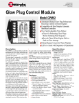
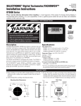
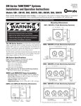
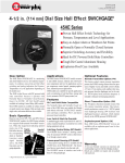
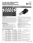
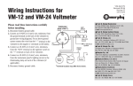
1
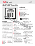
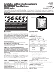
®
FRANK W.
S15-95063B
Effective 10-95
Catalog Section 50
MFR.
(00-02-0119)
SELECTRONIC® Micro-Controller
Series 1500
■ Alarm/Shutdown for 32 N.O. and/or N.C. Sensors
■ Operating Sequence Selection
■ Completely Field Adjustable
■ Selectable Sensor Lockouts Class A, B, C or P
■ Built-In Tachometer/Overspeed Function
DIS
CO
NT
INU
ED
■ Clearly Visible Alphanumeric Display
■ RS232 Communications Capability
■ Two Start/Run Timers
■ Elapsed Time Meter
®
NRTL/C
Approved for Class I,
Division 1 Groups C & D
Description
Applications
How to Order
The Series 1500 is a microprocessor based alarm
and/or shutdown system. It tells in alphanumeric
characters which protective device has signaled an
alarm or caused equipment shutdown. Basic configuration for each application is programmed at
Murphy and can be configured in the field.
Information is called up and adjustments are made
on a six-button keypad on the face of the unit.
The Series 1500 can be configured to monitor
■ Generators
applications such as:
■ Air compressors
■ Process control
■ Gas compressors
■ Water treatment
■ Fire pumps
■ Burner systems
■ Sewage pumps
■ Natural gas refueling
To order the Complete S1500 System: Monitor,
Terminal Block, Cable Assembly and Power
Supply), just specify the part number:
The S1500 system consists of a monitor, a sensor
input terminal strip (rail mount type), a 36 inch
(914 mm) flat ribbon cable for connecting the terminal strip to the monitor, and a power supply
which includes the control Inputs/Outputs and
intrinsically safe barrier with cable assembly.
Four SPDT relays are available for alarm and/or
shutdown functions. A built-in RS232 communication port allows interfacing with IBM® PC and compatible computer systems and micro-controllers.
The S1500 is powered from a 120 VAC or 12 or
24 VDC, Class I, Division 1 explosion-proof power
supply. The monitor is rated intrinsically safe.
Intrinsically Safe Barrier
Murphy’s LCDT-ISB intrinsically safe barrier for
hazardous applications, is designed for use with
two Normally Open sensors. This external barrier
accepts non-intrinsically safe, normally open inputs
and converts them to intrinsically safe outputs.
Features
32 sensor inputs (N.O. and/or N.C.) for alarm
or shutdown.
■ Six-button keypad for easy operation and
adjustments.
■ RS232 output for interface with computers and
micro-controllers (modem required).
■ Engine Automatic.
■ Two Start-Run Timers.
■ Four Control Relay Outputs.
■ Pre/Postlube Time Delay.
■ Typical standard program or customized*.
* Murphy provides various standard preprogrammed
■
configurations. If a customer sensor input configuration is needed, Murphy will custom program your
unit at the time you order. Call Murphy for quote.
Warranty
A two-year limited warranty on materials and
workmanship is given with this Murphy product.
Details are available on request and are packed
with each unit.
S1500
To order individual components and accessories
specify model number:
Specify:
To Order:
S1500H
Monitor (Head) only
S1500TB32 Terminal Block only
S1500CA36 Cable Assembly only
S1500PS
Power Supply only
LCDT-ISB
Intrinsically Safe Barrier
(for Normally Open Sensors*)
Shipping Weights and Dimensions
Complete S1500 System: 28 lb. [12.7 kg.]; 20 x
14 x 12-1/2 in. [508 x 356 x 318 mm]).
S1500 H: 2 lb. (0.907 kg.); 6 x 6 x 6 in. (152 x
152 x 152 mm).
S1500 TB32: 2 lb. (0.907 kg.); 12 x 7 x 4 in.
(305 x 178 x 102 mm).
S1500CA36: 2 lb. (0.907 kg.); 6 x 6 x 6 in.
( 152 x 152 x 152 mm).
S1500PS: 22 lb. (9.98 kg.); 17 x 10 x 9-3/4 in.
(431 x 254 x 248 mm).
LCDT-ISB: 3 lb. (1.3 kg.); 9 x 10 x 6 in. (229 x
254 x 152 mm).
* For Normally Closed sensor the use an intrinsically
safe (approved) barrier is required.
Specifications
Series 1500 System
Power Consumption: 120 VAC (8 watts), 12 or 24 VDC (2.5 or 7.2 watts).
Sensor Inputs: 32 N.O. and/or N.C., such as Murphy SWICHGAGE® instruments. Inputs are factory-programmed as a Class A, B, C or P for shutdown,
alarm, or control function (specify).
Opto-Isolated Input: 12-120 VDC or 24-120 VAC, the opto-isolated input is
typically used as a run input, magnetic pickup and ignition.
Outputs: 4-SPDT relays, 4 A, 1/20 HP, 125/250 VAC/3A, 30 VDC.
NOTE: An approved isolation barrier must be used between the sensor
switch and input terminals if the sensor output comes from any energy storing device such as a relay or transistor. (See LCDT-ISB Barrier, at right).
Timers: 12 adjustable timers for:
• Two Start-up lockouts • Test
• Prelube
• Postlube
• Load delay
• Idle
• Crank
• Rest
• Run delay
• Process delay
• Ignition ground
Time Delay: Delay before ignition ground or electric motor stop, for
up to 59 seconds.
Terminal Block: Rail mount DIN type; 32 positions (screw type).
Backup Battery: Rechargeable during normal operation.
Provides up to 5 hours backup time.
Tachometer Sensing: From either CD Ignition or Magnetic Pickup.
Operating Temperatures: 32 to 122°F (0 to 50°C).
Storage Temperatures: -4 to 158°F (-20 to 70°C).
Case: ABS plastic, 1/4 DIN (90 x 90 mm).
Interface Output: RS232 communication port.
Alphanumeric Display: 2 lines, each line with 16 characters (32 total).
Laboratory Approvals: CSA and NRTL/C for Cl. I, Div. 1, Grps. C & D.
Power Supply Enclosure: Explosion-proof, Class I, Division 1. Intrinsically
safe barrier built into power supply, 120 VAC and 12 or 24 VDC power
supply barrier with dry contact relay functions such as:
• Fuel valve
• Alarm
• Shutdown
• Ignition
• Control (Pre/Postlube)
• Compressor Loading
• Engine Cranking
DIS
CO
NT
INU
ED
Module,
Dimensions
LCDT-ISB Intrisically Safe Barrier:
External barrier explosion-proof design for hazardous locations, according
to NEC requirements for Class 1, Division 1 Group D areas. The LCDT-ISB
accepts Normally Open sensor inputs (2 inputs per barrier). For Normally
Closed sensors, an intrinsically safe (approved) barrier is required.
Te r m i n a l B l o c k ,
Module (Head)
SIDE VIEW
Power Supply
4-5/8 in.
(117 mm)
Mounting
Clamp
3-3/4 in.
(95 mm)
Power Supply
9 in.
(229 mm)
3-1/2 in.
(89 mm)
3 in.
(76 mm)
4-3/8 in.
(111 mm)
TOP VIEW
6-3/4 in.
(171 mm)
clearance for plug
BACK VIEW
MOUNTING HOLE
3-1/2 in.
(89 mm)
3-9/16 in.
(90 mm)
3-3/4 in.
(95 mm)
15 in.
(381 mm)
clearance
for conduit
10-1/2 in.
(267 mm)
4-1/2 in.
(114 mm)
3-9/16 in.
(90 mm)
8-3/4 in.
(222 mm)
Terminal Block
SIDE VIEW
FRONT VIEW
3-1/32 in.
(77 mm)
7 in.
(178 mm)
6 in.
(152 mm)
3/4 NPT
conduit fittings
(2) places
1/2 NPT conduit fitting
Relays, Timers, and Sensor Input Class
Ordering Your Configuration
Use the listings below to specify sensor input Class, Function and Nomenclature; the S1500 sensor inputs are factory-configured as follows:
Class A: Armed at all times for alarm or shutdown (specify).
Class B1: Locked out by first lockout timer (First Start/Run timer).
Class B2: Locked out by second lockout timer (Second Start/Run timer).
Class C: Armed after fault condition has been cleared for 2 seconds.
Class P: Locked out by the Compressor Load lockout timer.
ESD: Overrides the Test lockout timer (for Remote/Emergency Stop input).
SD: S1500 System Shutdown Function.
AL: Alarm Relay Function (no shutdown).
Sensor Input
Specify Class
Specify Function
Default Nomenclature
User Specified Nomenclature
Example:
Input 1
Input 2
Input 3
Input 4
Input 5
Input 6
Input 7
Input 8
Input 9
Input 10
Input 11
Input 12
Input 13
Input 14
Input 15
Input 16
Input 17
Input 18
Input 19
Input 20
Input 21
Input 22
Input 23
Input 24
Input 25
Input 26
Input 27
Input 28
Input 29
Input 30
Input 31
Input 32
Class B2
____________
____________
____________
____________
____________
____________
____________
____________
____________
____________
____________
____________
____________
____________
____________
____________
____________
____________
____________
____________
____________
____________
____________
____________
____________
____________
____________
____________
____________
____________
____________
____________
SD
_________________
_________________
_________________
_________________
_________________
_________________
_________________
_________________
_________________
_________________
_________________
_________________
_________________
_________________
_________________
_________________
_________________
_________________
_________________
_________________
_________________
_________________
_________________
_________________
_________________
_________________
_________________
_________________
_________________
_________________
_________________
_________________
Compressor Oil Pressure
Compressor Oil Pressure
Compressor Oil Level
Lubrication No-Flow
Low Suction Pressure
Interstage Pressure #1
Interstage Pressure #2
Interstage Pressure #3
Discharge Pressure
Discharge Temperature #1
Discharge Temperature #2
Discharge Temperature #3
Discharge Temperature #4
Suction Liquid Level
Interstage Liquid Level #1
Interstage Liquid Level #2
Interstage Liquid Level #3
Inlet Scrubber Liquid Level
Engine Oil Pressure
Engine Oil Level
Engine Oil Vibration
Engine Jacket Water Temp.
Engine Jacket Water Level
Engine Jacket Water Press.
Engine Vacuum Right Bank
Engine Vacuum Left Bank
Compressor Vibration
Cooler Vibration
Cooler Water Level
Auxiliary Pump Shutdown
Emergency Shutdown
PLC Shutdown
Prelube Permissive
Compressor #1 Oil Pressure
________________________
________________________
________________________
________________________
________________________
________________________
________________________
________________________
________________________
________________________
________________________
________________________
________________________
________________________
________________________
________________________
________________________
________________________
________________________
________________________
________________________
________________________
________________________
________________________
________________________
________________________
________________________
________________________
________________________
________________________
________________________
________________________
DIS
CO
NT
INU
ED
Select your Relay Logic Mode (see page 4):
TIMERS
MODE No. ____________________
Prelube: ___________________ (0:30)
Select your Timing and range; (default values)
TACHOMETER
Pulses/Rev.: _____________________ (60)
Crank Disconnect: _______________ (100)
Underspeed: ____________________ (150)
Overspeed: _____________________ (400)
Run Delay: _________________ (0:30)
Class B1: ___________________ (1:00)
Class B2: ___________________ (1:00)
Load Delay: _________________ (1:00)
Process Delay: _______________ (1:30)
Idle/Cooldown: _______________(5:00)
Ignition Ground: _______________ (0:10)
Postlube: ______________________ (0:30)
CRANKING
Attempts: ______________________ (5)
Crank Period: __________________ (0:15)
Rest Period: ____________________ (0:15)
Mode Char t
Logic Modes
Motor
Relay / Logic Mode Configurations Available
Ignition
Cooler
Load
K2
K3
Mode
01
02
K4
K4
K3
Mode
Mode
03
K4
K3
Mode
04
K4
K3
Mode
05
K4
Mode
06
K4
K2
Mode
07
K4
K2
Mode
08
K4
Mode
09
K4
Mode
10
K4
Mode
11
K4
Mode
12
K4
K3
Mode
13
K4
K3
Mode
14
Shutdown
K1
K2
K1
K1
K1
Lube
Crank
K2
K1
K1
K2
K1
Alarm
Fuel
K2
K3
K1
K3
K1
K3
K3
K2
K3
K2
K3
K2
K3
K1
K2
K2
K2
K1
K1
K1
K4
K2
K3
K1
DIS
CO
NT
INU
ED
Mode
15
K4
K3
K2
Mode
16
K4
Mode
17
K4
Mode
18
K4
Mode
19
K4
Mode
20
K4
Mode
21
K4
Mode
22
K4
K2
Mode
23
K4
K2
Mode
24
K4
Mode
25
K4
Mode
26
K4
Mode
27
K4
Mode
28
K4
Mode
29
K4
Mode
30
K4
Mode
31
K4
Mode
32
K4
Mode
33
K4
Mode
34
K4
Mode
35
K4
Mode
36
K4
K3
K1
Mode
37
K4
K2
K1
K3
Mode
38
K4
K1
K3
K2
Mode
39
K4
K1
K3
K2
Mode
40
K4
K3
Mode
41
K4
Mode
42
K4
Mode
43
K4
Mode
44
K4
Mode
45
K4
K3
K1
K2
K3
K2
K2
K1
K2
K3
K1
K3
K1
K3
K2
K2
K1
K1
K1
K1
K2
K1
K1
K2
K1
K2
K2
K1
K1
K1
®
Since 1939
MFR.
■ Frank W. Murphy Manufacturer
P.O. Box 470248; Tulsa, Oklahoma 74147; USA
tel. (918) 627-3550 fax (918) 664-6146
e-mail [email protected]
■ Frank W. Murphy Southern Division
P.O. Box 1819; Rosenberg, Texas 77471; USA
tel. (281) 342-0297 fax (281) 341-6006
e-mail [email protected]
Printed in U.S.A.
K3
K3
K3
K3
K3
K3
K2
K2
K2
K2
K2
K3
K1
K3
K1
K3
K1
K3
K1
K3
K2
K2
K1
K3
K2
K3
K2
K3
K3
K1
K1
K1
K3
K1
K2
■ Frank W. Murphy, Ltd.
Church Rd.; Laverstock, Salisbury SP1 1QZ; U.K.
tel. +44 1722 410055 fax +44 1722 410088 tlx 477088
e-mail [email protected]
■ Frank W. Murphy Pte., Ltd.
26 Siglap Drive; Republic of Singapore 456153
tel. +65 241-3166 fax +65 241-8382
e-mail [email protected]
■ Murphek Pty., Ltd.
1620 Hume Highway; Campbellfield, Vic 3061; Australia
tel. +61 3 9358-5555 fax +61 3 9358-5558
K3
K1
K1
In order to consistently bring you the highest quality, full featured products, we reserve the right to change our specifications and designs at any time.
FRANK W.
K3
K3
K2
K2
K2
K3
K2
K1
K2
K1
■ Murphy de México, S.A. de C.V.
Blvd. Antonio Rocha Cordero 300, Fracción del Aguaje
San Luis Potosí, S.L.P.; México 78384
tel. +52-48-206264 fax +52-48-206336
e-mail [email protected]
■ Murphy Switch of California
P.O. Box 900788; Palmdale, California 93590; USA
tel. (805) 272-4700 fax (805) 947-7570
e-mail [email protected]
■ Frank W. Murphy France
tel. +33 1 30 762626 fax +33 1 30 763989