1
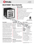
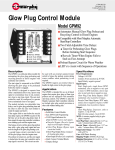
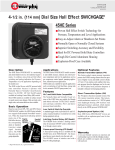
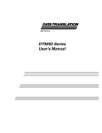
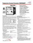
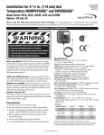
DT-8605N
Revised 07-97
Section 20
®
SELECTRONIC Digital Tachometer/TACHSWICH™
(00-02-0180)
Installation Instructions
®
DT9800 Series
Please read the following information before installing. A visual inspection of this product for damage during shipping is
recommended before mounting. It is your responsibility to have a qualified person install this unit and make sure installation
conforms to NEC and local codes.
GENERAL INFORMATION
*
®
WARNING
*
BEFORE BEGINNING INSTALLATION OF THIS MURPHY PRODUCT
✔
✔
✔
✔
Disconnect all electrical power to the machine.
Make sure the machine cannot operate during installation.
Follow all safety warnings of the machine manufacturer.
Read and follow all installation instructions.
Class I,
Division 2,
Group D
Description
Specifications
The Digital SELECTRONIC® DT9800 series features a tachometer-only and
tachometer with built-in overspeed switch. These tachometers are highly
accurate and dependable due to digital solid-state electronics and a quartz
crystal time base. The surface-mount enclosure makes it easy to install.
Tachometer power and RPM data are supplied by a magnetic pickup or
capacitor discharge (CD) ignition–depending on model chosen. The RPM
data is converted and displayed on a four digit, easy-to-read liquid crystal
display (LCD). The LCD displays up to 9999 RPM.
The DT9803 and DT9804 are tachometer-only models. The DT9803 is
powered by a magnetic pickup. The DT9804 is powered by a CD ignition.
The TACHSWICH™ models, DT9805 and DT9806, combine a digital
tachometer and overspeed switch. The DT9805 is powered by a magnetic
pickup and the DT9806 is powered by a CD ignition.
Input Signal Source
DT9803: 18 to 112 volts peak to peak or 3.5 to 40 Vrms.
DT9805: 18 to 112 volts peak to peak or 7 to 40 Vrms.
DT9804 and DT9806: 90 to 400 VDC, CD ignition.
Temperature Range: -4 to 158°F (-20 to 70°C).
Accuracy: ±1 RPM.
Frequency Range:
DT9803 and DT9805: 1 to 15 KHz.
DT9804 and DT9806: 3 to 666 Hz.
Overspeed Switch Rating (DT9805 and DT9806 only):
SCR output. 5 A @ 400 VDC.
* Class I, Div. 2, Group D Hazardous Locations. Models DT9803 and DT9805 magnetic pickup powered
18 to 112 Vpp input. Models DT9804 and DT9806 used with CD ignition. Contact Murphy for details.
The equipment must be installed in a suitable enclosure accepted by local authorities.
MOUNTING
1. Before installing, be sure there will be enough clearance to access the
calibration rocker switches and overspeed switches from the back of
the panel.
2. Drill mounting holes according to the dimensions below.
3. Be sure the gasket is in place on the back of the tachometer before
installing. Insert the tachometer from the front of the panel aligning the
mounting studs with the appropriate holes. Secure the tachometer using the
four 6/32 nuts, but do not overtighten the nuts as case damage could occur.
Back View
Mounting Hole Dimensions
Tachometer
Panel
Overspeed
Switches**
2 in.
(51 mm)
1 2 3 4 5 6 7 8 9 10 11 12
OPEN
78
901
23
78
901
23
23
78
901
456
2 in.
(51 mm)
3-1/8 in.
(79 mm)
diameter
Gasket
456
4 in.
(102 mm)
Calibration Rocker
Switches
456
3-1/2 in.
(89 mm)
3/16 in (5 mm)
diameter, 4 places
Wiring
Terminals
**Applies to overspeed models only.
1
DT9803 AND DT9804 TYPICAL WIRING
WARNING: PERFORM THE WIRING INSTALLATION WITH THE POWER SOURCE OFF. DO NOT
ROUTE TACHOMETER LEADS WITH PRIMARY IGNITION WIRING.
Figure 2: DT9804 typical wiring for negative ground ignition
DT9803
Back of
DT9804
NEG
90-150
Figure 1: DT9803 typical wiring
150-400
Connect the magnetic pickup cable conductors to the MPU terminal as
shown in Figure 1. Use a two conductor shielded cable between the
DT9803 and the magnetic pickup.
MPU
Negative Ground Ignition
Optional Connection for
150-400 V Ignitions
Back of
DT9803
Flywheel
2 Conductor
Shielded Cable
Belden or
Equivalent
Table 1: Output Voltage & Polarity of Common CD Ignitions
Magnetic Pickup
Ignition
MFG & Series
DT9804
Before wiring the DT9804, determine the output voltage and ground
polarity of the ignition. Table 1 lists the Peak Output Voltage and
Ground Polarity of some common ignitions.
Connect the DT9804 tachometer to the CD ignition. Figure 2 shows a
typical wiring diagram for negative ground ignition system.
Ground
Polarity
Peak Output
Voltage
Use Figure
Altronic I, III, & V
Negative
120
6
Altronic II
Positive
350
7
Bendix S-1800, BLAR
Negative
250
6
Bendix Side-winder
Positive
300
7
Fairbanks Morse SCSA
Positive
180
7
Fairbanks Morse
3000 & 9000
Negative
225
6
American Bosch Magtronic
Negative
165
6
DT9805 AND DT9806 TYPICAL WIRING
WARNING: PERFORM THE WIRING INSTALLATION WITH THE POWER SOURCE OFF.
DO NOT ROUTE TACHOMETER LEADS WITH PRIMARY IGNITION WIRING.
DT9805
Figure 4: DT9805 typical wiring for positive ground ignition
1. Connect the magnetic pickup as shown in Figure 3.
2. Connect the overspeed switch wiring as shown Figures 3 and 4.
Observe the polarity of the overspeed switch. The positive terminal
must be connected to the positive side of the circuit as shown.
3. If connecting to a Murphy LCDT annunciator refer to Figure 5. See
General Catalog for more information on the LCDT.
Connected to
Corresponding Numbers
On Terminal Block Below
307-PH-CD
TATTLETALE®
SWICHGAGE®
4
1
5
Pressure
Overspeed
Level
1
2
3
G
2
3
Back of
DT9805
Figure 3: DT9805 typical wiring for negative ground ignition
Emergency
Stop Switch
MPU
OS
SW
Frame
Ground
ALT 2
Connected to
Corresponding Numbers
On Terminal Block Below
1
5
Pressure
Overspeed
Level
1
2
3
G
2
2 Conductor
Shielded Cable
Belden or
Equivalent
3
GRD
Adapter
Package
1
2
3
4
5
6
7
8
Connect to
Good Engine
Ground
To Magnetic Pickup
To Positive Ground
CD Ignition
Back of
DT9805
Emergency
Stop Switch
MPU
OS
SW
Frame
Ground
ALT 2
ALT 1
POS
NEG
GRD
Adapter
Package
1
2
3
4
5
6
7
8
To Magnetic Pickup
To Negative Ground
CD Ignition
ignitions, reverse the
negative and positive wires
on the tachometer so that
the positive terminal is grounded.)
POS
Connect to
Good Engine
Ground
Figure 5:
Overspeed
Terminals
DT9805 and DT9806 Switch
on DT9805 or DT9806
negative ground
connection to Murphy
LCDT (for positive ground
NEG
2 Conductor
Shielded Cable
Belden or
Equivalent
2
POS
4
NEG
307-PH-CD
TATTLETALE®
SWICHGAGE®
ALT 1
Murphy LCDT
Annunciator
Terminal Block
46
50
DT9806
Before wiring the DT9806, determine the output voltage and ground
polarity of the ignition. Table 1 lists the Peak Output Voltage and Ground
Polarity of some common ignitions.
Figure 6 displays wiring to a negative ground ignition and Figure 7 for
positive ground units. If the ignition output voltage is 90-150 volts,
connect the ignition lead to the 90-150 input terminal on the DT9806; if it
is 150-400 volts, then connect the lead to the 150-400 terminal.
Figure 6: DT9806 typical wiring for negative ground ignition
If connecting to a Murphy LCDT annunciator refer to Figure 5. See
General Catalog for more information on the LCDT.
NOTE: When installing the DT9806 in a Murphy panel, always connect
the DT9806 to the ignition/input side of the power adapter. If the DT9806
input is connected to the output of the adapter, its display will read zero
RPM, since the adapter filters out the ignition pulses.
Figure 7: DT9806 typical wiring for positive ground ignition
CALIBRATING THE DT9800 SERIES TO YOUR ENGINE
1. Locate the calibration switches on back of the unit (see page 1).
2. If calibrating the DT9804 and DT9806 advance to step 3. If calibrating
the DT9803 and DT9805, find the number of teeth for your gear in
Table 2. Close the series of calibration switches listed next to the
number of gear teeth.
Calibration
Switches
1 2 3 4 5 6 7 8 9 10 11 12
Pushed
“ON”
(closed)
OPEN
Side View
DO NOT USE A PENCIL TO PUSH SWITCHES
3. To set the calibration code on the DT9804 and DT9806, refer to Table 3.
Find the line that matches your engine's cylinders and cycles and set the
DT9804/DT9806 according to the switches marked “ON”.
NOTE: if the ignition system has two energy storage capacitors, count only
half the actual number of engine cylinders for the calibration code.
Table 2: DT9803 and DT9805 Calibration Chart
Number
of Gear Close Switch
Teeth Number(s)
250
249
248
247
246
245
244
243
242
241
240
239
238
237
236
235
234
233
232
231
230
229
228
227
226
2-3-5-6-7-8
1-2-3-5-6-7-8
4-5-6-7-8
1-4-5-6-7-8
2-4-5-6-7-8
1-2-4-5-6-7-8
3-4-5-6-7-8
1-3-4-5-6-7-8
2-3-4-5-6-7-8
1-2-3-4-5-6-7-8
9
1-9
2-9
1-2-9
3-9
1-3-9
1-2-3-9
4-9
1-4-9
2-4-9
1-2-4-9
3-4-9
1-3-4-9
1-2-3-4-9
5-9
Number
of Gear Close Switch
Teeth Number(s)
225
224
223
222
221
220
219
218
217
216
215
214
213
212
211
210
209
208
207
206
205
204
203
202
201
1-5-9
2-5-9
3-5-9
1-3-5-9
2-3-5-9
2-3-5-9
1-4-5-9
2-4-5-9
1-2-4-5-9
3-4-5-9
2-3-4-5-9
1-2-3-4-5-9
6-9
2-6-9
1-2-6-9
1-3-6-9
2-3-6-9
1-2-3-6-9
1-4-6-9
2-4-6-9
3-4-6-9
1-3-4-6-9
1-2-3-4-6-9
5-6-9
2-5-6-9
Number
of Gear Close Switch
Teeth Number(s)
200
199
198
197
196
195
194
193
192
191
190
189
188
187
186
185
184
183
182
181
180
179
178
177
176
1-2-5-6-9
1-3-5-6-9
2-3-5-6-9
4-5-6-9
1-4-5-6-9
1-2-4-5-6-9
1-3-4-5-6-9
2-3-4-5-6-9
7-9
2-7-9
1-2-7-9
1-3-7-9
1-2-3-7-9
1-4-7-9
2-4-7-9
3-4-7-9
2-3-4-7-9
5-7-9
2-5-7-9
1-2-5-7-9
1-3-5-7-9
1-2-3-5-7-9
1-4-5-7-9
1-2-4-5-7-9
1-3-4-5-7-9
Number
of Gear Close Switch
Teeth Number(s)
175
174
173
172
171
170
169
168
167
166
165
164
163
162
161
160
159
158
157
156
155
154
153
152
151
1-2-3-4-5-7-9
1-6-7-9
1-2-6-7-9
1-3-6-7-9
1-2-3-6-7-9
1-4-6-7-9
3-4-6-7-9
2-3-4-6-7-9
5-6-7-9
2-5-6-7-9
3-5-6-7-9
1-2-3-5-6-7-9
1-4-5-6-7-9
1-2-4-5-6-7-9
2-3-4-5-6-7-9
8-9
2-8-9
1-3-8-9
1-2-3-8-9
2-4-8-9
3-4-8-9
1-2-3-4-8-9
1-5-8-9
3-5-8-9
1-2-3-5-8-9
150
149
148
147
146
145
144
143
142
141
140
139
138
137
136
135
134
133
132
131
130
129
128
127
126
125
124
123
122
121
2-4-5-8-9
3-4-5-8-9
1-2-3-4-5-8-9
2-6-8-9
1-3-6-8-9
4-6-8-9
1-2-4-6-8-9
2-3-4-6-8-9
1-5-6-8-9
3-5-6-8-9
1-2-3-5-6-8-9
2-4-5-6-8-9
1-3-4-5-6-8-9
7-8-9
3-7-8-9
1-2-3-7-8-9
1-2-4-7-8-9
2-3-4-7-8-9
1-5-7-8-9
1-3-5-7-8-9
1-4-5-7-8-9
3-4-5-7-8-9
6-7-8-9
3-6-7-8-9
4-6-7-8-9
3-4-6-7-8-9
1-2-3-4-6-7-8-9
3-5-6-7-8-9
4-5-6-7-8-9
3-4-5-6-7-8-9
120
119
118
117
116
115
114
113
112
111
110
109
108
107
106
105
104
103
102
101
100
99
98
97
96
95
94
93
92
91
10
3-10
1-4-10
1-3-4-10
1-5-10
2-3-5-10
1-2-4-5-10
6-10
1-3-6-10
2-4-6-10
1-2-3-4-6-10
3-5-6-10
1-4-5-6-10
2-3-4-5-6-10
3-7-10
1-4-7-10
1-2-3-4-7-10
1-3-5-7-10
2-4-5-7-10
6-7-10
2-3-6-7-10
1-3-4-6-7-10
1-2-5-6-7-10
4-5-6-7-10
8-10
1-2-3-8-10
2-3-4-8-10
1-3-5-8-10
3-4-5-8-10
1-2-6-8-10
90
89
88
87
86
85
84
83
82
81
80
79
78
77
76
75
74
73
72
71
70
69
68
67
66
65
64
63
62
61
1-2-4-6-8-10
2-5-6-8-10
2-4-5-6-8-10
2-7-8-10
2-4-7-8-10
1-2-5-7-8-10
1-2-4-5-7-8-10
3-6-7-8-10
3-4-6-7-8-10
1-2-3-5-6-7-8-10
9-10
2-4-9-10
3-5-9-10
2-3-4-5-9-10
4-6-9-10
1-2-5-6-9-10
2-3-4-5-6-9-10
2-4-7-9-10
1-3-5-7-9-10
1-6-7-9-10
2-3-4-6-7-9-10
2-4-5-6-7-9-10
4-8-9-10
1-3-5-8-9-10
1-2-6-8-9-10
1-5-6-8-9-10
7-8-9-10
1-2-3-4-7-8-9-10
1-2-3-4-5-7-8-9-10
1-2-3-4-6-7-8-9-10
60
59
58
57
56
55
54
53
52
51
50
49
48
47
46
45
44
43
42
41
40
39
38
37
36
35
34
33
32
11
1-5-11
1-2-6-11
2-3-5-6-11
1-4-7-11
1-3-4-5-7-11
2-5-6-7-11
1-2-3-8-11
2-3-4-5-8-11
1-3-5-6-8-11
1-3-4-7-8-11
2-3-6-7-8-11
9-11
1-2-4-5-9-11
4-5-6-9-11
1-3-5-7-9-11
3-5-6-7-9-11
1-3-5-8-9-11
1-2-3-5-6-8-9-11
1-2-4-5-7-8-9-11
10-11
1-2-3-6-10-11
1-5-7-10-11
1-3-4-5-6-7-10-11
1-2-4-6-8-10-11
1-2-4-5-7-8-10-11
1-2-3-4-9-10-11
2-3-7-9-10-11
8-9-10-11
Table 3: Calibration Code for DT9804 and DT9806
Number of
Cylinders
Number of
Cycles
1
2
2
3
4
4
5
5
6
6
8
8
10
12
16
2
2
4
2
2
4
2
4
2
4
2
4
4
4
4
1
2
3
Calibration Switch Code
4 5 6 7 8 9
10 11 12
ON ON
ON ON
ON ON
ON
ON ON
ON ON
ON
ON ON
ON
ON
ON ON
ON
ON
ON
ON ON
ON ON
ON
ON ON
ON
ON
ON ON
Consult Murphy for Cylinder and Cycle combinations not listed on this table
3
SETTING OVERSPEED SET POINTS: DT9805 AND DT9806
901
23
78
78
901
23
23
23
78
901
456
901
456
456
23
456
456
Figure 8:
Overspeed switch
set at 1850 RPM
78
X 10
901
78
X 100
901
78
X 1000
23
The overspeed set point switches are available on the DT9805 and
DT9806 only. The overspeed set point can be set within ± 5 RPM, over a
range of 0010 to 9990 RPM. Setting of the overspeed set points is made by
properly adjusting of three rotary switches. Each switch can be adjusted in
increments of ten. To set the switches perform the following:
1. Locate the three rotary switches on the back of the unit (Figure 8).
2. Insert a small blade screwdriver inside the arrow slot. Turn the
screwdriver until the arrow pointer is facing the number you choose.
EXAMPLE: You want the overspeed to trip at 1850 RPM (Figure 8):
(1) Rotate the X-1000-arrow to the (1),
(2) Rotate the X-100-arrow to the (8),
(3) Rotate the X-10-arrow to the five (5).
456
DT9804 AND DT9806 TROUBLESHOOTING
If the DT9804 or DT9806 tachometer reading is incorrect or erratic follow
the steps below in order until the devices read properly.
1. Check for proper voltage for your ignition system (90-150).
2. Check all grounds, be sure they are good and tight.
3. Separate ignition wires from primary coil wires.
4. Check switches for correct settings according to the number of engine
cylinders. Where the ignition system has two storage capacitors, the
tachometer must be set for half the number of engine cylinders.
DO NOT USE A PENCIL TO PUSH SWITCHES.
5. Check reading on 110 VAC 60 Hz with all switches open or on 0. The
display should read all 0's. Also refer to the calibration chart in step 9.
6. The shutdown lead must be separated at least 12 in. (305 mm) from the
high-tension spark plug leads. The best practice is to run the shutdown
lead from the junction box to the panel in a separate conduit.
7. The common ground for the capacitor discharge ignition system coils
must be grounded to the engine block, preferably as close to each coil
as possible.
8. If the Murphy adaptor package is used make sure the tach is connected
to the input (ALT 1, ALT 2) not the output.
9. Calibration Check: Hook 110 VAC 60 Hz hot to the input 90-150 and
the neutral to the negative input. These readings are ±1 RPM.
Dip Switches On
Reading
2, 4, 5
60
1, 5, 9
639
3, 6, 10
1284
2, 8, 11
2704
1, 7, 12
4951
Warranty
A two-year limited warranty on materials and workmanship is given with this
Murphy product. Details are available on request and are packed with each unit.
In order to consistently bring you the highest quality, full featured products, we reserve the right to change our specifications and designs at any time.
®
FRANK W.
Since 1939
MFR.
■ Frank W. Murphy Manufacturer
P.O. Box 470248; Tulsa, Oklahoma 74147; USA
tel. (918) 627-3550 fax (918) 664-6146
e-mail [email protected]
■ Frank W. Murphy Southern Division
P.O. Box 1819; Rosenberg, Texas 77471; USA
tel. (281) 342-0297 fax (281) 341-6006
e-mail [email protected]
Printed in U.S.A.
4
■ Frank W. Murphy, Ltd.
Church Rd.; Laverstock, Salisbury SP1 1QZ; U.K.
tel. +44 1722 410055 fax +44 1722 410088 tlx 477088
e-mail [email protected]
■ Frank W. Murphy Pte., Ltd.
26 Siglap Drive; Republic of Singapore 456153
tel. +65 241-3166 fax +65 241-8382
e-mail [email protected]
■ Murphek Pty., Ltd.
1620 Hume Highway; Campbellfield, Vic 3061; Australia
tel. +61 3 9358-5555 fax +61 3 9358-5558
■ Murphy de México, S.A. de C.V.
Blvd. Antonio Rocha Cordero 300, Fracción del Aguaje
San Luis Potosí, S.L.P.; México 78384
tel. +52-48-206264 fax +52-48-206336
e-mail [email protected]
■ Murphy Switch of California
P.O. Box 900788; Palmdale, California 93590; USA
tel. (805) 272-4700 fax (805) 947-7570
e-mail [email protected]
■ Frank W. Murphy France
tel. +33 1 30 762626 fax +33 1 30 763989
056499