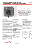
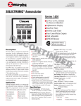
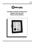
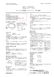
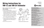
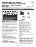
1
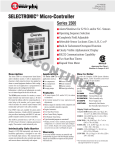
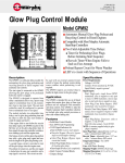
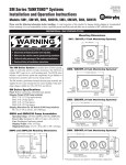
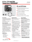
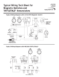
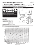
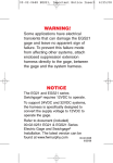
®
FRANK W.
45HE-95116B
Revised 12-96
Catalog Section 05/10/15
MFR.
(00-02-0221)
4-1/2 in. (114 mm) Dial Size Hall Effect SWICHGAGE®
45HE Series
■ Proven Hall Effect Switch Technology for
Pressure, Temperature and Level Applications
■ Easy-to-Adjust Alarm or Shutdown Set Points
■ Normally Open or Normally Closed Systems
■ Superior Switching Accuracy and Flexibility
■ Ideal for DC Powered Solid State Controllers
■ Tough Die Casted Aluminum Housing
■ Explosion-Proof Case Available
Description
Applications
Optional Features
The 45HE Series SWICHGAGE® is a monitoring
and alarm/shutdown device for industrial requirements. It combines state-of-the-art Hall effect
switching and analog indication for Pressure,
Temperature or Level applications depending on
the model used.
The 45HE is ideal for use with DC powered solid
state controllers because it operates with
Normally Open or Normally Closed Systems
from 4.5 to 28 VDC. 120 VAC On-Off control
available in Latching Control Relay (BP) models.
Most 45HE models are available in surface mount
or panel mount case designs. Dials are dual scale,
single scale, and custom dials are also available.
The 45HE Series SWICHGAGE® models accurately and reliably measure, indicate and control pressure, temperature and level in applications such as
gas compressor control panels, pumping applications, industrial process applications.
45HE models are available for specific applications
such as monitoring oil well lead lines, storage tank
levels, automatic ON/OFF pump control, etc.
Remote Transmitter Option (-P4)
Basic Operation
Based on our proven OPL, SPL and OPLH Series
SWICHGAGE® models, the 45HE Series includes
two magnetic-field-actuated PowerHall* transistors. When the magnetized indicating pointer
meets one of the Fingertip
PowerHall*
Hall effect devices, Adjustable
Transistor
the corresponding Trip Point
alarm or shutdown
15
transistor output
10
20
signal becomes
80 100 120
active. The 45HE
140
60
160
trip points are fingertip adjustable.
Magnetized
Indicating
Pointer
* Allegro MicroSystems, Inc., registered trademark.
Features
PLC and Solid State Compatible
The Normally Open and Normally Closed versions of the 45HE Series are suitable for Murphy
(and others) solid state TATTLETALE® annunciators and logic controllers, PLC’s and microprocessor-based controllers.
This factory-sealed, remote pressure transmitter
protects the 45PHE sensing element from line pressures of highly viscous and mildly corrosive fluids.
A 5 foot (1.5 m) stainless steel capillary tube transmits pressure from the diaphragm seal to the unit.
A 1 NPTM plated steel pulsation dampener is
included to help prevent damaging pulsation.
Direct Transmitter Option (-P6)
The -P6 option is the direct mounted version of the
-P4 (remote transmitter option). This factorysealed mechanism consists of a 2 NPTM plated
steel diaphragm housing (304 stainless steel
diaphragm housing is optional), which attaches
directly to the 45PHE pressure SWICHGAGE®.
Low Switch Start-Up Override
A standard toggle switch is provided (N.O. and N.C.
surface mounted models) to override the low switch
during equipment start-up.
Latching Control Relay (BP Model)
Explosion-proof Option (-EX)
Most 45HE Series SWICHGAGE® devices are
available with an explosion-proof case for hazardous applications.
The 45HEBP Series includes a latching control
relay for automatic ON/OFF control, either directly or through a motor starter.
Freeze-proof Sensing (FP Model)
A freeze-proof sensing device is available for the
45LHE Series level SWICHGAGE®. The freezeproof device inserts directly into the tank wall.
The 45LHEFP sensor is stainless steel with a
Buna-N rolling diaphragm.
Warranty
A two-year limited warranty on materials and
workmanship is given with this Murphy product.
Details are available on request and are packed
with each unit.
Specifications
Case: Die casted aluminum,
Dial: 4-1/2 in. (114 mm), white on black background.
Sensing Element: Bronze bourdon tube standard; 316 stainless steel or monel
are optional. 45LHEA and 45LHE Level models up to 20 ft. (6.09 m) brass
bellows is standard; stainless steel bellows is optional (see page 4).
Geared Movement: 302 and 304 stainless steel.
Lens: Clear Polycarbonate, UV stabilized, fog and scratch resistant.
SWICHGAGE® Sensor: PowerHall; outputs negative signal
(sinking transistor output) rated: 300 mA continuous.
SWICHGAGE® Set Points: 2-fingertip adjustable, visible on face-dial.
SWICHGAGE® Electrical Connection:
Surface Mount Case: Terminal block; 1/2 NPTF conduit connection.
Panel Mount Case: Wire leads, 18 AWG x 8 in. (1.0 mm2 x 203 mm);
1/2 NPTM conduit connection.
Optional Conduit Connection: 24 AWG x 8 in. (0.22 mm2 x 203 mm);
1/2 NPTM conduit connection.
Operating Temperature: -40 to 185°F (-40 to +85°C).
Storage Temperature: -77 to 185°F (-60 to 85°C).
Power Input: 4.5 to 28 VDC; 120 VAC/24VDC for Latching Control
Relay (BP) models with built-in transformer/rectifier.
Overrange: Do not exceed 30% above full range (all models).
Temperature Models Sensing Connections:
Capillary: 5 feet (1.5 m) PVC armored copper tube, standard.
(Other options available see “How to Order” section, page 4).
Sensing Bulb: Copper, 1/2 in. (13 mm) O.D. x 7 in. (178 mm) length;
600 psi (4.14 MPa) [41.37 bar] pressure rating, for higher pressure
ratings the use of thermowell is recommended.
Sensing Bulb Connection: 1/2 NPTM.
Temperature Models Accuracy
Temperature Range
Lower 1/4
Middle 1/2
Upper 1/4
-60 to 60°F
(-51 to 16°C)
-40 to 136°F
(-40 to 58°C)
15 to 250°F
(9 to 121°C)
130 to 350°F
(60 to 180°C)
260 to 450°F
(127 to 232°C)
± 2°F
(± 1°C)
± 4°F
(± 2°C)
± 8°F
(± 4°C)
± 8°F
(± 4°C)
± 8°F
(± 4°C)
± 2°F
(± 1°C)
± 2°F
(± 1°C)
± 2°F
(± 1°C)
± 2°F
(± 1°C)
± 2°F
(± 1°C)
± 2°F
(± 1°C)
± 2°F
(± 1°C)
± 2°F
(± 1°C)
± 3°F
(± 1.5°C)
± 3°F
(± 1.5°C)
Level Models Sensing Connections:
45LHE, 45LHEF: Bottom connection 1/4 NPTM.
Bellows Mov. Models (up to 20 ft. [6 m] range): Bottom connection 1/4 NPTF.
45LHEFP: 2 NPTM back connection.
Level Models Accuracy: ± 2% for the first and last quarters of the scale,
the middle half of scale is ±1%.
Pressure Models Sensing Connection: Bottom connection 1/4 NPTM thru
1000 psi (6.89 MPa) [68.9 bar], or 1/2 NPTM 1500 psi (10.3 MPa) [103 bar]
thru 20,000 psi (137 MPa) [1378 bar], back connection optional.
Pressure Models Accuracy: ± 2% for the first and last quarters of the scale,
the middle half of scale is ±1%.
Internal Wiring
Important information: When using the 45HE SWICHGAGE® with inductive loads, we recommend installing a suppression diode across all coil(s).
45PHENC, 45THENC
and 45LHENC Series
45PHEBP, 45THEBP and
45LHEBP Series (12/24 VDC)
45PHEBP, 45THEBP and
45LHEBP Series (120 VAC)
Contacts Shown Reset
(Low Limit has been Met)
Contacts Shown Reset
(Low Limit has been Met)
+ –
3
9
6
B
2
4
= 26 AWG (0.12 mm )
2
Red= Positive Power Input
Green= Negative Power Input
White= Low Transistor Sinking Output
Black= High Transistor Sinking Output
Black
White
Red
Green
1
2
4
= 26 AWG (0.12 mm2)
Red= Positive Power Input
Green= Negative Power Input
White= Low Transistor Sinking Output
Black= High Transistor Sinking Output
Hall Effect Sensors Ratings: 300 mA continuous
Note 1: Start/Run Switch; Open for Start,
Closed for Run (surface mount models only).
Note 2: Start/Run Switch; Closed for Start,
Open for Run (surface mount models only).
Customer
Connections
12 or 24 VDC
+
1
Red
4
Blue
8
High
+ –
--
= 26 AWG (0.12 mm2)
= 16 AWG (1.5 mm2)
Customer
Connections
120 VAC
Low
Red
2 Green
9
B
5
Green
Red
Green
Brown
5
6
Black
Set
Relay Coils
8
A
5
Reset
Red
N
+ –
3
4
3
5
A
Reset
Yellow
1
7
Black
Set
Relay Coils
Red
1
Black
White
Red
Green
3
3
Brown
White
Note 2
Note 1
3
4
High
+ –
+ –
7
1 White
Low
High
+ –
+ –
White
Low
High
+ –
1
Red
Low
Yellow
Blue
Black
4
2 Black
H
= 26 AWG (0.12 mm )
= 18 AWG (1.0 mm2)
= 16 AWG (1.5 mm2)
2
Green
Full Wave
Rectifier
Red
Green
Latching Relay Contact Ratings: SPDT Dry Relay Contacts, 10 A @ 120 VAC
Black
45PHE, 45THE and
45LHE Series
Dimensions
Surface Mount 45PHE and 45LHE Series
8-7/16 in.
(214 mm)
3-3/8 in.
(86 mm)
3-15/16 in.
(100 mm)
4-1/32 in.
(102 mm)
Panel Mount 45PHEF and 45LHEF Series
Panel Mount
Square Case*
models
do not
include
mounting
flange
5-7/16 in.
(138 mm)
2-57/64 in.
(73 mm)
120
120
1/2 in.
(13 mm)
conduit
120
Mounting Hole
4-3/4 in.
(121 mm)
diameter.
7-7/8 in.
(200 mm)
1/4 in. (6 mm) dia.
holes (3 places.) on
5-13/64 in. (132 mm)
b.c. (bolt circle),
120 apart, clocking
as shown
9/32 in.
(7 mm) dia.
3 places
Optional conduit
and -ES Option
1/2 in. (13 mm)
* 45PHEE, 45LHEE, 45PHENCE, 45LHENCE, 45PHEBPE and 45LHEBPE models
feature square case, but altered to fit standard round panel mounting–not pictured.
Panel Mount 45THEF Series
Surface Mount 45THE Series
8-7/16 in.
(214 mm)
3-15/16 in.
(100 mm)
4-1/32 in.
(102 mm)
3-3/8 in.
(86 mm)
5-7/16 in.
(138 mm)
Panel Mount
Square Case**
models
do not
include
mounting
1/2 in.
flange
(13 mm)
2-57/64 in.
(73 mm)
120
120
conduit
120
Mounting Hole
4-3/4 in.
(121 mm)
diameter.
7-7/8 in.
(200 mm)
1/4 in. (6 mm) dia.
holes (3 places.) on
5-13/64 in. (132 mm)
b.c. (bolt circle),
120 apart, clocking
as shown
9/32 in.
(7 mm) dia.
3 places
Optional
coduit
and -ES
Option,
1/2 in.
(13 mm)
Temperature Sensing Bulb
7 in.
(178 mm)
1/2 NPT
** 45THEE, 45THENCE and 45THEBPE versions feature square case,
but altered to fit standard round panel mounting–not pictured.
Bulb Minimum Insertion
Explosion-proof -EX Option
3-3/8 in.
(86 mm)
8 in.
(203 mm)
45LHEFP Freeze-proof
6-25/64 in.
(162 mm)
8 in.
(203 mm)
Compression Nut
10-13/16 in.
(275 mm)
1/2 NPT
optional
rear or side
conduit
4-1/8 in.
(105 mm)
3/8-16 UNC-2B
thread
7/8 in. (22 mm)
deep, 8 plc's
Process
Connection
2 NPT
6-3/4 in.
(171 mm)
13/32 in.
(10 mm)
diameter
4 places
3-3/8 in.
(86 mm)
6-3/4 in. (171 mm)
7-35/64 in.
(192 mm) dia.
Mounting hole required
for Panel mount models
Surface Mounted Case
How to Order
Specify model number. List options in alphabetical order (A to Z). Place a dash (–) between each option. See example below.
45PHE – R – 2 – 30 – CC
Base Models for Pressure
45PHE (surface mount)
45PHEF (panel mount)
45PHEE (panel)†
45PHEBP (surface)
Pressure/Vacuum Range/Scale
45PHENC (surface)
45PHEFNC (panel)
45PHENCE (panel)†
45PHEBPE (panel)†
30V
30V15
30V30
30V100
30V200
30V300
15
30
60
100
160
200
300
400
600
1000
1500
2000
3000
5000
10000
20000
Base Models for Temperature
45THE (surface mount)
45THEF (panel mount)
45THEE (panel)†
45THEBP (surface)
45THENC (surface)
45THEFNC (panel)
45THENCE (panel)†
45THEBPE (panel)†
Base Models for Level
45LHE (surface mount)
45LHEF (panel mount)
45LHEE (panel)†
45LHEBP (surface)
45LHENC (surface)
45LHEFNC (panel)
45LHENCE (panel)†
45LHEBPE (panel)†
45LHEFP(freeze-proof)
Bourdon Tube/Bellows
A = Bronze bourdon tube with brass socket–up to 1000 psi.
= Brass bellows (level models 20 ft./6.09 m. and below only).
R = 316 Stainless steel bourdon tube with carbon steel socket.
S = 316 Stainless steel bourdon tube and socket.
= 316 Stainless steel bellows movement.
P = “K” Monel bourdon tube with monel 400 socket
(Special order. Check delivery and price.)
A1 = 1/2 NPT–up to 1000 psi.
R1 = 1/2 NPT–up to 1000 psi.
S1 = 1/2 NPT–up to 1000 psi.
P1 = 1/2 NPT–up to 1000 psi.
30" vac - 0 psi
30" vac - 15 psi
30" vac - 30 psi
30" vac - 100 psi
30" vac - 200 psi
30" vac - 300 psi
0 - 15 psi
0 - 30 psi
0 - 60 psi
0 - 100 psi
0 - 160 psi
0 - 200 psi
0 - 300 psi
0 - 400 psi
0 - 600 psi
0 - 1000 psi
0 - 1500 psi
0 - 2000 psi
0 - 3000 psi
0 - 5000 psi
0 - 10,000 psi
0 - 20,000 psi
Standard*(Do not specify) = 120 VAC systems.
2 = 12 VDC systems.
3 = 24 VAC systems.
4 = 24 VDC systems.
* Includes transformer/rectifier 120VAC/24VAC.
BC = Back connected
bourdon tube
CC = Conduit connection
ES = Environmentally sealed
EX = Explosion-proof
EL = Explosion-proof less case
LC = Less case
P4 = Pressure transmitter
with 5 ft. (1.52 m)
P4L = Less pulsation dampener
P6 = Pressure transmitter
direct mount
P6S = Pressure transmitter direct
mount, 304 st. st. housing
RO = Restricting orifice
SH = Stainless steel external
hardware
T3 = Tamperproof bezel/lens
TS = Over/under range stop
VR = Vapor recovery compensator
Temperature (Specify one from each column)
Temperature Range
Capillary Type
60 = -60 - 60°F (15.6°C)
136 = 40 - 136°F (57.8°C)
250 = 15 - 250°F (121°C)
350 = 130 - 350°F (177°C)
450 = 260 - 450°F (232°C)
P = PVC Armor/Copper Capillary
G = Galvanized/Copper Capillary
S = Stainless St./St. St. Capillary
T = Stainless St./Copper Capillary
Capillary Length
Specify in feet
Specify in meters
05 = 5 ft. (1.5 m)
10 = 10 ft. (3 m)
15 = 15 ft. (4.5 m)
etc.
1.5M = 1.5 m
2M = 2 m
2.5M = 2.5 m
etc.
Level Range/Scale
Specify in feet
Latching Control Relay Voltage (for “BP” models only)
Options
-101 kPa - 0 kPa
-101 kPa - 103 kPa
-101 kPa - 207 kPa
-101 kPa - 689 kPa
-101 kPa - 1.38 MPa
-101 kPa - 2.07 MPa
0 - 103 kPa
0 - 207 kPa
0 - 414 kPa
0 - 689 kPa
0 - 1.10 MPa
0 - 1.38 MPa
0 - 2.07 MPa
0 - 2.76 MPa
0 - 4.14 MPa
0 - 6.89 MPa
0 - 10.34 MPa
0 - 13.79 MPa
0 - 20.68 MPa
0 - 34.48 MPa
0 - 68.95 MPa
0 - 137.90 MPa
5**= 0 - 5 ft. (0-1.5 m) Dual scale
10**= 0 - 10 ft. (0-3 m) Dual scale
20**= 0 - 20 ft. (0-6 m) Dual scale
30 = 0 - 30 ft. (0-9 m) Dual scale
60 = 0 - 60 ft. (0-18 m) Dual scale
120 = 0 - 120 ft. Single scale
Specify in meters
4M= 0 - 4 m Single scale
3.5M= 0 - 3.5 m Single scale
6M= 0 - 6 m Single scale
90 = 0 - 9 m Single scale
NOTES: Standard calibration is for water–specify if
other. To determine correct
range, add TOTAL height
of liquid above the pressure
connection.
For elevated tanks subtract
tank elevation from gage
reading to determine
ACTUAL tank level.
**Bellows actuated level models instead of bourdon tube.
† Features square case, but for panel mounting.
In order to consistently bring you the highest quality, full featured products, we reserve the right to change our specifications and designs at any time.
®
FRANK W.
Since 1939
MFR.
■ Frank W. Murphy Manufacturer
P.O. Box 470248; Tulsa, Oklahoma 74147; USA
tel. (918) 627-3550 fax (918) 664-6146
e-mail [email protected]
■ Frank W. Murphy Southern Division
P.O. Box 1819; Rosenberg, Texas 77471; USA
tel. (281) 342-0297 fax (281) 341-6006
e-mail [email protected]
Printed in U.S.A.
■ Frank W. Murphy, Ltd.
Church Rd.; Laverstock, Salisbury SP1 1QZ; U.K.
tel. +44 1722 410055 fax +44 1722 410088 tlx 477088
e-mail [email protected]
■ Frank W. Murphy Pte., Ltd.
26 Siglap Drive; Republic of Singapore 456153
tel. +65 241-3166 fax +65 241-8382
e-mail [email protected]
■ Murphek Pty., Ltd.
1620 Hume Highway; Campbellfield, Vic 3061; Australia
tel. +61 3 9358-5555 fax +61 3 9358-5558
■ Murphy de México, S.A. de C.V.
Blvd. Antonio Rocha Cordero 300, Fracción del Aguaje
San Luis Potosí, S.L.P.; México 78384
tel. +52-48-206264 fax +52-48-206336
e-mail [email protected]
■ Murphy Switch of California
P.O. Box 900788; Palmdale, California 93590; USA
tel. (805) 272-4700 fax (805) 947-7570
e-mail [email protected]
■ Frank W. Murphy France
tel. +33 1 30 762626 fax +33 1 30 763989