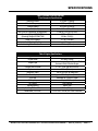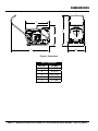
1
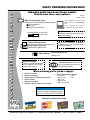
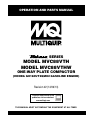
Operation and Parts Manual SERIES MODEL MVC88VTH MODEL MVC88VTHW ONE-WAY plate compactor (HONDA GX160UT2QMX2 GASOLINE ENGINE) Revision #2 (12/09/13) To find the latest revision of this publication, visit our website at: www.multiquip.com THIS MANUAL MUST ACCOMPANY THE EQUIPMENT AT ALL TIMES. proposition 65 warning page 2 — MVC88VTH/VTHW PLATE COMPACTOR • operation and parts manual — rev. #2 (12/09/13) notes MVC88VTH/VTHW PLATE COMPACTOR • operation and parts manual — rev. #2 (12/09/13) — page 3 Table of Contents MVC88VTH/MVC88VTHW Forward Plate Compactor Proposition 65 Warning............................................ 2 Table Of Contents..................................................... 4 Parts Ordering Procedures....................................... 5 Safety Information............................................... 6-10 Specifications......................................................... 11 Dimensions............................................................. 12 General Information................................................ 13 Compactor Components......................................... 14 Compactor Components......................................... 15 Inspection............................................................... 16 Inspection............................................................... 17 Startup............................................................... 18-19 Operation................................................................ 20 Operation/Maintenance.......................................... 21 Maintenance...................................................... 22-25 Explanation Of Code In Remarks Column............. 26 Suggested Spare Parts.......................................... 27 Compactor Component Drawings Honda GX160UTQMX2 Engine Component Drawings Cylinder Head Assembly................................... 42-43 Cylinder Barrel Assembly.................................. 44-45 Crankcase Cover Assembly.............................. 46-47 Crankshaft Assembly......................................... 48-49 Piston Assembly................................................ 50-51 Camshaft Assembly........................................... 52-53 Recoil Starter Assembly.................................... 54-55 Fan Cover Assembly......................................... 56-57 Carburetor Assembly......................................... 58-59 Air Cleaner Assembly........................................ 60-61 Muffler Assembly............................................... 62-63 Fuel Tank Assembly........................................... 64-65 Flywheel Assembly............................................ 66-67 Ignition Coil Assembly....................................... 68-69 Control Assembly.............................................. 70-71 Decals................................................................ 72-73 Terms and Conditions of Sale — Parts.................. 74 Body Assembly.................................................. 28-31 Vibrator Assembly............................................. 32-33 Transport Wheel Assembly................................ 34-35 Sprinkler Assembly............................................ 36-37 Urethane Plate Assembly.................................. 38-39 Nameplate and Decals...................................... 40-41 NOTICE Specifications and part numbers are subject to change without notice. page 4 — MVC88VTH/VTHW PLATE COMPACTOR • operation and parts manual — rev. #2 (12/09/13) www.multiquip.com Parts Ordering Procedures Ordering parts has never been easier! Choose from three easy options: Order via internet (dealers Only): best deal! Effective: January 1st, 2006 If you have an MQ Account, to obtain a Username and Password, E-mail us at: parts@multiquip. com. Order parts on-line using Multiquip’s SmartEquip website! ■ View Parts Diagrams ■ Order Parts ■ Print Specification Information To obtain an MQ Account, contact your District Sales Manager for more information. Use the internet and qualify for a 5% discount on Standard orders for all orders which include complete part numbers.* Goto www.multiquip.com and click on Order Parts to log in and save! Note: Discounts Are Subject To Change Order via Fax (dealers Only): All customers are welcome to order parts via Fax. domestic (us) Customers dial: 1-800-6-PARTS-7 (800-672-7877) Fax your order in and qualify for a 2% discount on Standard orders for all orders which include complete part numbers.* Note: Discounts Are Subject To Change Order via phone: domestic (us) dealers Call: 1-800-427-1244 non-dealer Customers: Contact your local Multiquip Dealer for parts or call 800-427-1244 for help in locating a dealer near you. International Customers should contact their local Multiquip Representatives for Parts Ordering information. When ordering parts, please supply: ❒ ❒ ❒ ❒ ❒ ❒ dealer account number dealer name and address shipping address (if different than billing address) Return Fax number applicable Model number quantity, part number and description of each part ❒ specify preferred Method of shipment: ✓ UPS/Fed Ex ✓ DHL ■ Priority One ✓ Truck ■ Ground ■ Next Day ■ Second/Third Day NOTICE All orders are treated as Standard Orders and will ship the same day if received prior to 3PM PST. We aCCepT aLL MaJOR CRediT CaRds! MVC88VTH/VTHW PLATE COMPACTOR • operation and parts manual — rev. #2 (12/09/13) — page 5 Safety Information Do not operate or service the equipment before reading the entire manual. Safety precautions should be followed at all times when operating this equipment. Failure to read and understand the safety messages and operating instructions could result in injury to yourself and others. Potential hazards associated with the operation of this equipment will be referenced with hazard symbols which may appear throughout this manual in conjunction with safety messages. saFeTy Messages The four safety messages shown below will inform you about potential hazards that could injure you or others. The safety messages specifically address the level of exposure to the operator and are preceded by one of four words: dangeR, WaRning, CauTiOn or nOTiCe. saFeTy syMbOLs dangeR Indicates a hazardous situation which, if not avoided, WiLL result in deaTH or seRiOus inJuRy. WaRning Indicates a hazardous situation which, if not avoided, COuLd result in deaTH or seRiOus inJuRy. CauTiOn Indicates a hazardous situation which, if not avoided, COuLd result in MinOR or MOdeRaTe inJuRy. NOTICE Addresses practices not related to personal injury. page 6 — MVC88VTH/VTHW PLATE COMPACTOR • operation and parts manual — rev. #2 (12/09/13) Safety Information geneRaL saFeTy CauTiOn neVeR operate this equipment without proper protective clothing, shatterproof glasses, respiratory protection, hearing protection, steel-toed boots and other protective devices required by the job or city and state regulations. neVeR operate this equipment when not feeling well due to fatigue, illness or when under medication. neVeR operate this equipment under the influence of drugs or alcohol. aLWays check the equipment for loosened threads or bolts before starting. dO nOT use the equipment for any purpose other than its intended purposes or applications. NOTICE This equipment should only be operated by trained and qualified personnel 18 years of age and older. Whenever necessary, replace nameplate, operation and safety decals when they become difficult read. Manufacturer does not assume responsibility for any accident due to equipment modifications. Unauthorized equipment modification will void all warranties. neVeR use accessories or attachments that are not recommended by Multiquip for this equipment. Damage to the equipment and/or injury to user may result. aLWays know the location of the nearest fire extinguisher. aLWays know the location of the nearest first aid kit. aLWays know the location of the nearest phone or keep a phone on the job site. Also, know the phone numbers of the nearest ambulance, doctor and fire department. This information will be invaluable in the case of an emergency. aLWays clear the work area of any debris, tools, etc. that would constitute a hazard while the equipment is in operation. MVC88VTH/VTHW PLATE COMPACTOR • operation and parts manual — rev. #2 (12/09/13) — page 7 Safety Information COMpaCTOR saFeTy dangeR neVeR operate the equipment in an explosive atmosphere or near combustible materials. An explosion or fire could result causing severe bodily harm or even death. WaRning neVeR disconnect any emergency or safety devices. These devices are intended for operator safety. Disconnection of these devices can cause severe injury, bodily harm or even death. Disconnection of any of these devices will void all warranties. CauTiOn neVeR lubricate components or attempt service on a running machine. NOTICE aLWays keep the machine in proper running condition. Fix damage to machine and replace any broken parts immediately. aLWays store equipment properly when it is not being used. Equipment should be stored in a clean, dry location out of the reach of children and unauthorized personnel. WaRning dO nOT place hands or fingers inside engine compartment when engine is running. neVeR operate the engine with heat shields or guards removed. Keep fingers, hands hair and clothing away from all moving parts to prevent injury. CauTiOn neVeR touch the hot exhaust manifold, muffler or cylinder. Allow these parts to cool before servicing equipment. NOTICE neVeR run engine without an air filter or with a dirty air filter. Severe engine damage may occur. Service air filter frequently to prevent engine malfunction. neVeR tamper with the factory settings of the engine or engine governor. Damage to the engine or equipment can result if operating in speed ranges above the maximum allowable. neVeR tip the engine to extreme angles during lifting as it may cause oil to gravitate into the cylinder head, making the engine start difficult. engine saFeTy dangeR The engine fuel exhaust gases contain poisonous carbon monoxide. This gas is colorless and odorless, and can cause death if inhaled. The engine of this equipment requires an adequate free flow of cooling air. neVeR operate this equipment in any enclosed or narrow area where free flow of the air is restricted. If the air flow is restricted it will cause injury to people and property and serious damage to the equipment or engine. page 8 — MVC88VTH/VTHW PLATE COMPACTOR • operation and parts manual — rev. #2 (12/09/13) Safety Information FueL saFeTy baTTeRy saFeTy (eLeCTRiC sTaRT OnLy) dangeR dangeR dO nOT add fuel to equipment if it is placed inside truck bed with plastic liner. Possibility exists of explosion or fire due to static electricity. FUEL dO nOT drop the battery. There is a possibility that the battery will explode. dO nOT expose the battery to open flames, sparks, cigarettes, etc. The battery contains combustible gases and liquids. If these gases and liquids come into contact with a flame or spark, an explosion could occur. WaRning FUEL aLWays wear safety glasses when handling the battery to avoid eye irritation. The battery contains acids that can cause injury to the eyes and skin. Use well-insulated gloves when picking up the battery. dO nOT start the engine near spilled fuel or combustible fluids. Diesel fuel is extremely flammable and its vapors can cause an explosion if ignited. aLWays refuel in a well-ventilated area, away from sparks and open flames. aLWays use extreme caution when working with flammable liquids. dO nOT fill the fuel tank while the engine is running or hot. dO nOT overfill tank, since spilled fuel could ignite if it comes into contact with hot engine parts or sparks from the ignition system. Store fuel in appropriate containers, in well-ventilated areas and away from sparks and flames. neVeR use fuel as a cleaning agent. dO nOT smoke around or near the equipment. Fire or explosion could result from fuel vapors or if fuel is spilled on a hot engine. aLWays keep the battery charged. If the battery is not charged, combustible gas will build up. dO nOT charge battery if frozen. Battery can explode. When frozen, warm the battery to at least 61°F (16°C). aLWays recharge the battery in a well-ventilated environment to avoid the risk of a dangerous concentration of combustible gases. If the battery liquid (dilute sulfuric acid) comes into contact with clothing or skin, rinse skin or clothing immediately with plenty of water. If the battery liquid (dilute sulfuric acid) comes into contact with eyes, rinse eyes immediately with plenty of water and contact the nearest doctor or hospital to seek medical attention. CauTiOn aLWays disconnect the negaTiVe battery terminal before performing service on the equipment. aLWays keep battery cables in good working condition. Repair or replace all worn cables. MVC88VTH/VTHW PLATE COMPACTOR • operation and parts manual — rev. #2 (12/09/13) — page 9 Safety Information TRanspORTing saFeTy CauTiOn NEVER allow any person or animal to stand underneath the equipment while lifting. NOTICE When the life cycle of this equipment is over, remove battery and bring to appropriate facility for lead reclamation. Use safety precautions when handling batteries that contain sulfuric acid. When the life cycle of this equipment is over, it is recommended that the trowel frame and all other metal parts be sent to a recycling center. Before lifting, make sure that the equipment parts (hook and vibration insulator) are not damaged and screws are not loose or missing. Metal recycling involves the collection of metal from discarded products and its transformation into raw materials to use in manufacturing a new product. Always make sure crane or lifitng device has been properly secured to the lifting bail (hook) of the equipment. Recyclers and manufacturers alike promote the process of recycling metal. Using a metal recycling center promotes energy cost savings. aLWays shutdown engine before transporting. neVeR lift the equipment while the engine is running. Tighten fuel tank cap securely and close fuel cock to prevent fuel from spilling. Use adequate lifting cable (wire or rope) of sufficient strength. Use one point suspension hook and lift straight upwards. dO nOT lift machine to unnecessary heights. aLWays tie down equipment during transport by securing the equipment with rope. enViROnMenTaL saFeTy/deCOMMissiOning NOTICE Decommissioning is a controlled process used to safely retire a piece of equipment that is no longer serviceable. If the equipment poses an unacceptable and unrepairable safety risk due to wear or damage or is no longer cost effective to maintain (beyond life-cycle reliability) and is to be decommissioned (demolition and dismantlement),be sure to follow rules below. eMissiOns inFORMaTiOn NOTICE The gasoline engine used in this equipment has been designed to reduce harmful levels of carbon monoxide (CO), hydrocarbons (HC) and nitrogen oxides (NOx) contained in gasoline exhaust emissions. This engine has been certified to meet US EPA Evaporative emissions requirements in the installed configuration. Attempting to modify or make adjustments to the engine emmission system by unauthorized personnel without proper training could damage the equipment or create an unsafe condition. Additionally, modifying the fuel system may adversely affect evaporative emissions, resulting in fines or other penalties. emission Control Label The emission control label is an integral part of the emission system and is strictly controlled by regulation(s). The label must remain with the engine for its entire life. If a replacement emission label is needed, please contact your authorized engine distributor. dO nOT pour waste or oil directly onto the ground, down a drain or into any water source. Contact your country's Department of Public Works or recycling agency in your area and arrange for proper disposal of any electrical components, waste or oil associated with this equipment. page 10 — MVC88VTH/VTHW PLATE COMPACTOR • operation and parts manual — rev. #2 (12/09/13) Specifications Table 1. MVC88VTH/VTHW One-Way Plate Compactor Specifications Centrifugal Force 3,372 lbs. (1,530 kg) Vibration Frequency 6,000 vpm (60 Hz) Traveling Speed 82 ft/min (25 m/min) Plate Size (L x W) 19.7 x 20.7 in (.500 x .525 mm) Max. Area of Compaction (no extensions) 8,100 sq. ft./hr (752 sq. m/hr) Operating Weight MVC88VTGH 207 lbs. (95 kg.) Operating Weight MVC88VTHW 229 lbs. (104 kg.) Water Tank Capacity 13.7 qt (13.0 liters) Anti-Vibration Handle Yes Lubricating Oil in Vibration Case 6.7 fl. oz. (200 cc) Table 2. Engine Specifications Engine Make Engine Model Engine Type Cylinder Bore X Stroke Displacement Maximum Ouput Fuel Tank Capacity Fuel Type Oil Capacity Air Cleaner Starting Method Dry Net Weight Recoil/Electric Dimensions (L x W x H) HONDA GX160UT2QMX2 Air-cooled 4 stroke, Single Cylinder, OHV, Horizontal Shaft Gasoline Engine 2.7 in. x 1.8 in. (68 mm x 45 mm) 163 cc (9.9 cu-in) 4.8 HP (3.6 kW) @ 3600 RPM Approx. .825 U.S. gallons (3.1 liters) Unleaded 86 Octane or Higher .61 qts (0.58 liters) Dual Element Recoil Start 33 lbs (15 Kg.) 12.2 x 14.3 x 13.6 in (312 x 362 x 346 mm) MVC88VTH/VTHW PLATE COMPACTOR • operation and parts manual — rev. #2 (12/09/13) — page 11 dimensions A D B C E Figure 1. Dimensions Table 3. Dimensions REF. DES IN. (MM) A 24.5 (622) B 22.5 (571) C 43.5 (1,105) D 36.0 (914) E 19.7 (500) page 12 — MVC88VTH/VTHW PLATE COMPACTOR • operation and parts manual — rev. #2 (12/09/13) general information Definition of Plate Compactor Frequency/Speed The Mikasa MVC88VTH/VTHW is a walk behind, plate compactor designed for the compaction of sand, mixed soils and asphalt. This plate compactor is a powerful compacting tool capable of applying a tremendous force in consecutive high frequency vibrations to a soil surface. Its applications include compacting for road, embankments and reservoirs as well as backfilling for gas pipelines, water pipelines and cable installation work. The compactor's vibrating plate produces a vibration frequency of 6,000 VPM (vibrations per minute). The travel speed of the compactor is approximately 82 ft/ minute (25 meters/minute). Vibratory Plates The vibratory plates of the compactor produce low amplitude high frequency vibrations, designed to compact granular soils and asphalt. The resulting vibrations cause forward motion. The engine and handle are vibration isolated from the vibrating plate. Engine These plate compactors are equipped with a Honda GX160UT2QMX2 air cooled, 4-cycle gasoline engine. The engine drives an eccentric weight at a high speed to develop a compaction force. In addition this engine is equipped with an oil alert system that will automatically stop the engine before the engine falls below safe engine oil operating limits. Always be sure to check the engine oil level prior to starting the engine. Controls Before starting the plate compactor identify and understand the function of all the controls and components. MVC88VTH/VTHW PLATE COMPACTOR • operation and parts manual — rev. #2 (12/09/13) — page 13 compactor components 1 MVC88VTHW MVC88VTH 2 9 3 4 8 10 5 OFF 6 ON 7 11 Figure 2. Plate Compactor Components Figure 2 shows the location of the basic controls and components of the MVC88VTH/VTHW Plate Compactor. The function of each control is described below: 1. Handle Bar – When operating the compactor use this handle bar to manuever the compactor. 2. Lifting Bale – When lifting of the compactor is required either by forklift, crane etc., tie rope or chain around this lifting point. 3. Fuel Tank Cap – Remove this cap to add fuel. Use only unleaded fuel with an octane rating of 86 or higher 4. Water Tank Cap (VTHW Only) – Remove this cap to add water to the water tank. 5. Water Tank (VTHW only) – Holds 13.7 quarts of water (removable, no tools required). 6. Vibrating Plate – A flat, open plate made of durable cast iron construction used in the compacting of soil. 7. Water Tube-Sprinkler (VTHW Only) – Supplies water to the soil via a splash plate. 8. Water Shut-Off Valve (VTHW Only) – Turn this valve downward to let water flow from the water tank to the water tube. 9. Engine – These plate compactors use a Honda GX160, 4.8 HP, air-cooled 4 stroke gasoline engine. Refer to the Honda owner's manual for more detailed engine information and related topics. 10. Belt Cover – Remove this cover to gain acess to the V-belts. NEVER run the compactor without the V-belt cover. If the V-belt cover is not installed, the possibility exists that your hand may get caught between the V-belt and clutch, causing serious injury and bodily harm. 11. Eccentric Housing – Encloses the eccentric, gears and counter weights. page 14 — MVC88VTH/VTHW PLATE COMPACTOR • operation and parts manual — rev. #2 (12/09/13) compactor components 1 9 8 2 7 12 6 5 11 4 10 3 Figure 3. Engine Controls and Components INITIAL SERVICING The engine (Figure 3) must be checked for proper lubrication and filled with fuel prior to operation. Refer to the manufacturer's engine manual for instructions and details of operation and servicing. 1. Fuel Filler Cap – Remove this cap to add unleaded gasoline to the fuel tank. Make sure cap is tightened securely. DO NOT over fill. DANGER Add fuel to the tank only when the engine is stopped and has had an opportunity to cool down. In the event of a fuel spill, DO NOT attempt to start the engine until the fuel residue has been completely wiped up and the area surrounding the engine is dry. 2. Throttle Lever – Used to adjust engine RPM speed. For normal operation this lever should always be placed in the RUN position. 3. Recoil Starter (Pull Rope) – Manual-starting method. Pull the starter grip until resistance is felt, then pull briskly and smoothly. 4. Fuel Valve Lever – OPEN to let fuel flow, CLOSE to stop the flow of fuel. 5. Choke Lever – Used in the starting of a cold engine, or in cold weather conditions. The choke enriches the fuel mixture. 6. Air Cleaner – Prevents dirt and other debris from entering the fuel system. Remove wing-nut on top of air filter canister to gain access to filter element. NOTICE Operating the engine without an air filter, with a damaged air filter, or a filter in need of replacement will allow dirt to enter the engine, causing rapid engine wear. 7. Spark Plug – Provides spark to the ignition system. Set spark plug gap according to engine manufacturer's instructions. Clean spark plug once a week. 8. Muffler – Used to reduce noise and emissions. NEVER touch when hot! 9. Fuel Tank – Fill with unleaded gasoline. Reference Table 2 for fuel tank capacity. For additional information refer to Honda engine owner's manual. 10. Dipstick/Oil Filler Cap – Remove this cap to determine if the engine oil is low. Add oil through this filler port as recommended in (Table 4). 11. Oil Drain Plug – Remove this plug to remove oil from the engine's crankcase. 12. Engine ON/OFF Switch – ON position permits engine starting, OFF position stops engine operation. MVC88VTH/VTHW PLATE COMPACTOR • operation and parts manual — rev. #2 (12/09/13) — page 15 inspection Before Starting DANGER 1. Read all safety instructions at the beginning of manual. EXPLOSIVE FUEL! 2. Clean the compactor, removing dirt and dust, particularly the engine cooling air inlet, carburetor and air cleaner. Motor fuels are highly flammable and can be dangerous if mishandled. DO NOT smoke while refueling. DO NOT attempt to refuel the compactor if the engine is hot! or running. 3. Check the air filter for dirt and dust. If air filter is dirty, replace air filter with a new one as required. 4. Check carburetor for external dirt and dust. Clean with dry compressed air. 5. Check fastening nuts and bolts for tightness. Fuel Check 1. Visually inspect (Figure 6) to see if fuel level is low. If fuel is low, replenish with unleaded fuel. Engine Oil Check FUEL CAP 1. To check the engine oil level, place the compactor on secure level ground with the engine stopped. 2. Remove the dipstick from the engine oil filler hole (Figure 4) and wipe clean. Figure 6. Fuel Check Figure 4. Engine Oil Dipstick Removal 3. Insert and remove the dipstick without screwing it into the filler neck. Check the oil level shown on the dipstick. 4. If the oil level is low (Figure 5), fill to the edge of the oil filler hole with the recommended oil type as listed in Table 4. Reference Table 2 for maximum engine oil capacity. 2. When refueling, be sure to use a strainer for filtration. DO NOT top-off fuel. Wipe up any spilled fuel immediately. Water Tank (Option) If your unit is equipped with a water tank (Figure 7) and your applications requires water, fill water tank. WATER TANK WATER SOURCE Figure 5. Engine Oil Dipstick (Oil Level) Table 4. Oil Type Season Temperature Oil Type Summer 25°C or Higher SAE 10W-30 Spring/Fall 25°C~10°C SAE 10W-30/20 Winter 0°C or Lower SAE 10W-10 Figure 7. Water Tank Filling page 16 — MVC88VTH/VTHW PLATE COMPACTOR • operation and parts manual — rev. #2 (12/09/13) inspection V-belt V-Belt Tension V-Belt Cover Removal The V-belt tension is proper if the V-belt bends 10 to 15 mm (Figure 10) when depressed with finger at midway between the clutch and vibrator pulleys. To inspect the V-belt, remove the three bolts that secure the belt cover to the frame as shown in Figure 8. REMOVE VIBRATOR CORRECT V-BELT TENSION 10-15 MM WHEN DEPRESSED AS SHOWN. CLUTCH PULLEY REMOVE V-BELT V-BELT asa ik M VIBRATOR PULLEY V-BELT COVER Figure 8. V-Belt Cover Removal V-Belt Inspection Visually examine the V-belt (Figure 9) and determine if it is full of tiny cracks, frayed, has pieces of rubber missing, is peeling or otherwise damaged. Also, examine the belt and determine if it is oil soaked or "glazed " (hard shiny appearance on the sides of the belt). Either of these two conditions can cause the belt to run hot, which can weaken it and increase the danger of it breaking. If the V-belt exhibits any of the referenced wear conditions replace the V-belt immediately Figure 10. V-Belt Tension Vibrator Oil Check 1. Place the plate compactor horizontally on a flat surface. Make sure the compactor is level when checking the oil in the vibrator assembly. 2. Check vibrator oil level by removing the oil plug (vibrator oil gauge) as shown in Figure 11. The oil level should be up to the oil plug. 3. The vibrator holds approximately 6.7 oz. (200 cc). IMPORTANT, if oil is required, replace using only SAE 10W-30 motor oil. VIBRATOR OIL SOAKED OIL PLUG PACKING GLAZED CORD FAILURE WORN BACK COVER BROKEN MISSING RUBBER Figure 11. Vibrator Oil Check CRACKS SIDEWALL WEAR Figure 9. Drive Belt Inspection MVC88VTH/VTHW PLATE COMPACTOR • operation and parts manual — rev. #2 (12/09/13) — page 17 startup CAUTION DO NOT attempt to operate the compactor until the Safety, General Information and Inspection sections of this manual have been read and thoroughly understood. 3. Place the choke lever (Figure 14) in the “CLOSED” position if starting a cold engine. CHOKE LEVER This section is intended to assist the operator with the initial start-up of the compactor. It is extremely important that this section be read carefully before attempting to use the compactor in the field. Starting the Engine 1. Place the engine fuel valve lever (Figure 12) to the “ON” position. CLOSED Figure 14. Choke Lever (Closed) NOTICE The CLOSED position of the choke lever enriches the fuel mixture for starting a COLD engine. The OPEN position provides the correct fuel mixture for normal operation after starting, and for restarting a warm engine. 4. Place the engine ON/OFF switch (Figure 15) in the "ON" position. Figure 12. Engine Fuel Valve Lever (ON Position) 2. Move the throttle lever (Figure 13) away from the idle position, about 1/3 of the way toward the run position. Figure 15. Engine ON/OFF Switch (ON Position) 5. Grasp the starter grip (Figure 16) and slowly pull it out. The resistance becomes the hardest at a certain position, corresponding the compression point. Rewind the rope a little from that point and pull out sharply. Figure 13. Throttle Lever (1/3 Start Position) page 18 — MVC88VTH/VTHW PLATE COMPACTOR • operation and parts manual — rev. #2 (12/09/13) startup 9. If the sprinkling of water is required, place water valve in the ON position. OFF ON Figure 16. Starter Grip NOTICE Figure 18. Water Valve (ON) 10. To begin compacting, place the throttle lever (Figure 19) in the “RUN” position. DO NOT pull the starter rope all the way to the end DO NOT release the starter rope after pulling. Allow it to rewind as soon as possible. 6. When engine starts, release the starter grip and allow the rope to recoil. 7. If the choke lever was moved to the "CLOSED" position to start the engine gradually move it to the "OPEN" position (Figure 17) as the engine warms up. If the engine has not started repeat steps 1 through 6. Figure 19. Throttle Lever (Run) CHOKE LEVER OPEN Figure 17. Choke Lever (Open) 8. Before the compactor is placed in to operation, run the engine for several minutes. Check for fuel leaks, and noises that would associate with a lose component. MVC88VTH/VTHW PLATE COMPACTOR • operation and parts manual — rev. #2 (12/09/13) — page 19 operation Operation CAUTION ALWAYS follow all safety rules referenced in the safety section of this manual before operating compactor. Keep work area clear of debris and other objects that could cause damage to the compactor or bodily injury. Stopping the Engine Normal Shutdown 1. Move the throttle lever to the idle position (Figure 20) and run the engine for three minutes at low speed. 1. Once the engine has started, move the engine throttle lever quickly to the run position. 2. With the throttle lever in the run position, the engine speed should be around 2,300 RPM, therefore engaging the centrifugal clutch. NOTICE ALWAYS move the throttle lever quickly without hesitation, because increasing the engine speed slowly causes the clutch to slip. Figure 20. Throttle Lever (Idle) 2. Place the engine ON/OFF switch (Figure 21) in the "OFF" position. ENGINE SWITCH 3. Firmly gasp the compactor's handle bar with both hands, the compactor will begin moving forward. OFF 4. Slowly walk behind the compactor and be on the lookout for any large objects or foreign matter that might cause damage to the compactor or bodily injury. NOTICE NEVER stop the engine suddenly while working at high speeds. ON Figure 21. Engine ON/OFF Switch (OFF Position) 3. Place the fuel shut-off lever (Figure 22) in the "OFF" position. 5. Compactor traveling speed may drop on soils which contain clay, however there may be cases where traveling speed drops because the compaction plate does not leave the ground surface easily due to the composition of the soil. To rectify this problem do the following: Check the bottom plate to see if clay or equivalent material has been lodge in the plate mechanism. If so, wash with water and remove. Figure 22. Fuel Valve Lever (OFF) Remember the compactor does not work as efficiently on clay or soils that have a high moisture content level. 4. If applicable place water valve (Figure 18) in the OFF position. If the soil has a high moisture level, dry soil to appropriate moisture content level or carry out compaction twice. Emergency Shutdown 1. Move the throttle lever quickly to the IDLE position, and place the engine ON/OFF switch in the OFF position. page 20 — MVC88VTH/VTHW PLATE COMPACTOR • operation and parts manual — rev. #2 (12/09/13) operation/maintenance maintenance General Cleanliness General maintenance practices are crucial to the performance and longevity of your compactor. This equipment requires routine cleaning, inspection and lubrication. Reference Table 5 and Table 6 for scheduled engine and compactor maintenance. Clean the compactor daily. Remove all dust and debris buildup (mud, clay etc.). If the compactor is steam-cleaned, ensure that lubrication is accomplished AFTER steam cleaning. The following procedures, devoted to maintenance, can prevent serious compactor damage or malfunctioning. NOTICE Reference HONDA engine manual supplied with your compactor for more detailed engine maintenance and troubleshooting. CAUTION NOTICE Inspection and other services should always be carried out on hard and level ground with the engine shutdown. NOTICE The inspection intervals listed in the maintenance tables are for operation under normal conditions. Adjust your inspection intervals based on the number hours plate compactor is in use, and particular working conditions. ALWAYS allow the engine to cool before servicing. NEVER attempt any maintenance work on a hot engine. CAUTION ALWAYS disconnect the spark plug wire from the spark plug and secure away from the engine before performing maintenance or adjustments on the machine. WARNING Some maintenance operations may require the engine to be run. Ensure that the maintenance area is well ventilated. Gasoline engine exhaust contains poisonous carbon monoxide gas that can cause unconsciousness and may result in DEATH MVC88VTH/VTHW PLATE COMPACTOR • operation and parts manual — rev. #2 (12/09/13) — page 21 maintenance Inspection and Maintenance Service Tables To make sure your plate compactor is always in good working condition before using, carry out the maintenance inspection in accordance with Table 5 and Table 6. Engine Maintenance Perform engine maintance as listed in Table 5. Description (3) Engine Oil Air Cleaner All Nuts and Bolts Spark Plug Cooling Fins Spark Arrester Fuel Tank Fuel Filter Idle Speed Valve Clearance Fuel lines Operation Table 5. Engine Maintenance Schedule Every 6 Every 3 First Before Month or Months or Months or 50 hrs 25 hrs 10 hrs X X X X (1) CHECK CHANGE CHECK CHANGE Re-tighten If Necessary CHECK-CLEAN REPLACE CHECK CLEAN CLEAN CHECK CHECK-ADJUST CHECK-ADJUST CHECK Every Year or 100 hrs Every 2 Years or 200 hrs X X X X X X X X (2) X (2) Every 2 years (replace if necessary) (2) 1. Service more frequently when used in DUSTY areas. 2. These items should be serviced by your service dealer, unless you have the proper tools and are mechanically proficient. Refer to the HONDA Shop Manual for service procedures. 3. For commercial use, log hours of operation to determine proper maintenance intervals. page 22 — MVC88VTH/VTHW PLATE COMPACTOR • operation and parts manual — rev. #2 (12/09/13) maintenance Machine Inspection Engine Air Cleaner DANGER Perfom machine inspection as listed in Table 6. Table 6. Machine Inspection Interval Check Solution Machine Clean if necessary. Fuel Tank For Leaks Repair fuel leaks. Fuel System for Leaks Repair fuel leaks. Engine Oil Add oil if necessary. Vibrator Oil Add oil if necessary. Air Cleaner Element Clean/Replace Daily Before Starting Guard Frame Inspect/deformations Shock Absorber Replace if damaged. Engine Oil Replace only after first 20 hrs. Engine Oil Change Air Cleaner Element Clean/Replace Vibrator Oil Check oil level. Check for leaks. V-Belt Inspect, replace if damaged or worn. Clutch Inspect, replace if not working properly. Engine Bolts Replace bolts if deformed or elongated. Vibrator Oil Change Every 20 Hours Every 100 Every 200 hours Every 300 hours Every 2 years Fuel Filter Change Fuel Lines Replace DO NOT use gasoline or low flash point solvents for cleaning the air cleaner. The possibility exists of fire or explosion which can cause damage to the equipment and severe bodily harm or even DEATH! CAUTION Wear protective equipment such as approved safety glasses or face shields and dust masks or respirators when cleaning air filters with compressed air. This engine is equipped with a replaceable, high-density paper air cleaner element. See (Figure 23) for air cleaner components. 1. Remove the air cleaner cover and foam filter element. 2. Tap the paper filter element several times on a hard surface to remove dirt, or blow compressed air not exceeding 30 psi (207 kPa, 2.1 kgf/cm2) through the filter element from the inside out. NEVER brush off dirt. Brushing will force dirt into the fibers. Replace the paper filter element if it is excessively dirty. Tightening Torque Reference Table 7 below (Tightening Torque ), for retightening of nuts and bolts. Table 7. Tightening Torque (in. kg/cm Diameter) Material 6mm 8mm 10mm 12mm 14mm 16mm 18mm 20mm 4T 70 150 300 500 750 1,100 1,400 2,000 6-8T 100 250 500 800 1,300 2,000 2,700 3,800 11T 150 400 800 1,200 2,000 2,900 4,200 5,600 * 100 (6mm) 300 ~ 350 (8mm) 650 ~ 700 (10mm) ** In case counter-part is of aluminum BLOW COMPRESSED AIR FROM THE INSIDE OUT Bolt threads used with this machine are all right handed Material and quality of material is marked on each bolt, and screw. Figure 23. Engine Air Cleaner MVC88VTH/VTHW PLATE COMPACTOR • operation and parts manual — rev. #2 (12/09/13) — page 23 maintenance 3. Clean foam element in warm, soapy water or nonflammable solvent. Rinse and dry thoroughly. Dip the element in clean engine oil and completely squeeze out the excess oil from the element before installing. 3. Thread spark plug into cylinder hole by hand to prevent cross-threading, then tighten securely. GAP .028 - .031 IN. (0.7- 0.8 MM.) NOTICE Operating the engine with loose or damaged air cleaner components could allow unfiltered air into the engine causing premature wear and failure. Engine Oil 1. Drain the engine oil when the oil is warm as shown in (Figure 24). OIL FILLER CAP DIPSTICK Figure 25. Spark Plug Gap V-belt Visually examine the V-belt (Figure 26) and determine if it is full of tiny cracks, frayed, has pieces of rubber missing, is peeling or otherwise damaged. Also, examine the belt and determine if it is oil soaked or "glazed " (hard shiny appearance on the sides of the belt). Either of these two conditions can cause the belt to run hot, which can weaken it and increase the danger of it breaking. DRAIN BOLT SEALING WASHER If the V-belt exhibits any of the above wear conditions replace the V-belt immediately. Figure 24. Draining Engine Oil OIL SOAKED 2. Remove the oil drain bolt and sealing washer and allow the oil to drain into a suitable container. 3. Replace engine oil with recommended type oil as listed in Table 4. For engine oil capacity, see Table 2 (Engine Specifications). DO NOT overfill. 4. Reinstall drain bolt with sealing washer and tighten securely. GLAZED Spark Plug WORN BACK COVER NOTICE BROKEN NEVER use a spark plug of incorrect heat range. 1. Remove and clean spark plug (Figure 25) with a wire brush if it is to be reused. Discard spark plug if the insulator is cracked or chipped. 2. Using a feeler gauge adjust spark plug gap to 0.028 ~0.031 inch (0.7~0.8 mm). CORD FAILURE MISSING RUBBER CRACKS SIDEWALL WEAR Figure 26. V-Belt Inspection page 24 — MVC88VTH/VTHW PLATE COMPACTOR • operation and parts manual — rev. #2 (12/09/13) maintenance spark arrester cleaning Clean the spark arrester every 6 months or 100 hours. 1. Remove the 4 mm screw (3) from the exhaust deflector, then remove the deflector. See (Figure 27). 4. Carefully remove carbon deposits from the spark arrester screen (Figure 28) with a wire brush. WIRE BRUSH 2. Remove the 5 mm screw (4) from the muffler protector, then remove the muffler protector. 3. Remove the 4 mm screw from the spark arrestor, then remove the spark arrester SPARK ARRESTER SCREEN 5MM SCREW (4) Figure 28. Cleaning The Spark Arrester DEFLECTOR MUFFLER PROTECTOR 4MM SCREW (3) 5. If the spark arrester is damaged and has breaks or holes, replace with a new one. 6. Reinstall the spark arrester and muffler protector in reverse order of disassembly. 4MM SCREW (1) SPARK ARRESTER Figure 27. Spark Arrester Removal MVC88VTH/VTHW PLATE COMPACTOR • operation and parts manual — rev. #2 (12/09/13) — page 25 EXPLANATION OF CODE IN REMARKS COLUMN The following section explains the different symbols and remarks used in the Parts section of this manual. Use the help numbers found on the back page of the manual if there are any questions. NOTICE The contents and part numbers listed in the parts section are subject to change without notice. Multiquip does not guarantee the availability of the parts listed. saMpLe paRTs LisT nO. 1 2% 2% 3 4 paRT nO. paRT naMe qTy. ReMaRks 12345 BOLT .....................1 .....INCLUDES ITEMS W/% WASHER, 1/4 IN. ..........NOT SOLD SEPARATELY 12347 WASHER, 3/8 IN. ..1 .....MQ-45T ONLY 12348 HOSE ..................A/R ...MAKE LOCALLY 12349 BEARING ..............1 .....S/N 2345B AND ABOVE nO. Column unique symbols — All items with same unique symbol (@, #, +, %, or >) in the number column belong to the same assembly or kit, which is indicated by a note in the “Remarks” column. duplicate item numbers — Duplicate numbers indicate multiple part numbers, which are in effect for the same general item, such as different size saw blade guards in use or a part that has been updated on newer versions of the same machine. NOTICE When ordering a part that has more than one item number listed, check the remarks column for help in determining the proper part to order. paRT nO. Column numbers used — Part numbers can be indicated by a number, a blank entry, or TBD. TBD (To Be Determined) is generally used to show a part that has not been assigned a formal part number at the time of publication. A blank entry generally indicates that the item is not sold separately or is not sold by Multiquip. Other entries will be clarified in the “Remarks” Column. qTy. Column numbers used — Item quantity can be indicated by a number, a blank entry, or A/R. A/R (As Required) is generally used for hoses or other parts that are sold in bulk and cut to length. A blank entry generally indicates that the item is not sold separately. Other entries will be clarified in the “Remarks” Column. ReMaRks Column Some of the most common notes found in the “Remarks” Column are listed below. Other additional notes needed to describe the item can also be shown. assembly/kit — All items on the parts list with the same unique symbol will be included when this item is purchased. Indicated by: “INCLUDES ITEMS W/(unique symbol)” serial number break — Used to list an effective serial number range where a particular part is used. Indicated by: “S/N XXXXX AND BELOW” “S/N XXXX AND ABOVE” “S/N XXXX TO S/N XXX” specific Model number use — Indicates that the part is used only with the specific model number or model number variant listed. It can also be used to show a part is NOT used on a specific model or model number variant. Indicated by: “XXXXX ONLY” “NOT USED ON XXXX” “Make/Obtain Locally” — Indicates that the part can be purchased at any hardware shop or made out of available items. Examples include battery cables, shims, and certain washers and nuts. “not sold separately” — Indicates that an item cannot be purchased as a separate item and is either part of an assembly/kit that can be purchased, or is not available for sale through Multiquip. page 26 — MVC88VTH/VTHW PLATE COMPACTOR • operation and parts manual — rev. #2 (12/09/13) Suggested Spare Parts mvc88vth/mvc88vtwh PLATE COMPACTOR with HONDA GX160UT2QMX2 GASOLINE engine 1 to 5 units Qty.P/NDescription 3 ...........070100332.............V-BELT 5............0650140480...........SPARK PLUG 1............28462ZH8003........ROPE, RECOIL STARTER 5............17210ZE1517........ELEMENT, AIR CLEANER 1............17620Z4H020........CAP, FUEL TANK 1............17672Z4H000........FUEL FILTER, FUEL TANK 4............939010230.............SHOCK ABSORBER NOTICE Part numbers on this Suggested Spare Parts list may supersede/replace the part numbers shown in the following parts lists. MVC88VTH/VTHW PLATE COMPACTOR • operation and parts manual — rev. #2 (12/09/13) — page 27 body assy. 45 53 51 52 43 A 57 42 60 44 63 54 62 45 43 59 61 41 37 38 39 35 36 38 39 34 32 31 33 56 55 31 32 (EG) 57 9 34 58 35 10 11 12 19 7 6 18-4 15 16 29 26 6 27 28 5 7 13 2 64 65 36 4 8 18-5 18-1 18-2 24 18-3 23 20 18 21 22 26 27 28 17 14 26 27 28 3 25 3 4 2 1 page 28 — MVC88VTH/VTHW PLATE COMPACTOR • operation and parts manual — rev. #2 (12/09/13) body assy. NO. A 1 2 3 4 5 6 7 8 9 10 11 12 13 14 15 16 17 18 18-1 18-2 18-3 18-4 18-5 19 20 21 22 23 24 25 26 27 28 29 31 32 33 34 35 36 37 38 39 41% PART NO. 416910120 416120141 939010230 020310080 030210250 416120390 001221025 030210250 416454360 912216015 001220850 030208200 031108160 416466520 416466540 031108160 022710809 959404350 416910100 416464490 416351320 080200300 080600550 042006006 90745ZE1600 416452809 952400130 009110004 070100332 416120950 416010040 001220825 030208200 031108160 001220820 952408710 404433430 416452360 952405600 001221253 030212300 416121050 0105091025 030210250 416121010 PART NAME QTY. REMARKS HANDLE ASSY...................................................1................INCLUDES ITEMS W/% VIBRATING PLATE 1 SHOCK ABSORBER 4 NUT M10 4 WASHER, LOCK M10 4 BASE 1 BOLT 10X25 4 WASHER, LOCK M10 4 RUBBER PLATE 25X25X8 1 ENGINE ASSY.,GX160UT2QMX2 1 BOLT 8X50 4 WASHER, LOCK M8 4 WASHER, FLAT M8 4 ENGINE NUT 1 ENGINE NUT 1 WASHER, FLAT M8 1 NYLON NUT M8 1 EARTH WIRE, 1" 1 CLUTCH ASSY 1 CLUTCH DRUM, 1" 1 CLUTCH SHOE AND BOSS ASSY. 1 STOP RING, S30 1 STOP RING, AR55 1 BEARING 6006 1 KEY 4.78X4.78X38 1 COLLAR 1 WASHER 1 SOCKET HEAD BOLT 5/16" 1 VBELT RPF3330 1 BELT COVER, INNER 1 BELT COVER, OUTER 1 BOLT 8X25 4 WASHER, LOCK M8 5 WASHER, FLAT M8 5 BOLT 8X20 1 COLLAR 13X20X44 2 RUBBER 20X32X28 2 HANDLE STOPPER 2 WASHER 12.5X35X4.5 2 BOLT 12X65 2 WASHER, LOCK M12 2 GUARD HOOK 1 BOLT 10X25 4 WASHER, LOCK M10 4 VAS HANDLE BODY 1 MVC88VTH/VTHW PLATE COMPACTOR • operation and parts manual — rev. #2 (12/09/13) — page 29 body assy. (CONTINUED) 45 53 51 52 43 A 57 42 60 44 63 54 62 45 43 59 61 41 37 38 39 35 36 38 39 34 32 31 33 56 55 31 32 (EG) 57 9 34 58 35 10 11 12 19 7 6 18-4 15 16 29 26 6 27 28 5 7 13 2 64 65 36 4 8 18-5 18-1 18-2 24 18-3 23 20 18 21 22 26 27 28 17 14 26 27 28 3 25 3 4 2 1 page 30 — MVC88VTH/VTHW PLATE COMPACTOR • operation and parts manual — rev. #2 (12/09/13) body assy. (CONTINUED) NO. 42% 43% 44% 45% 51 52 53 54 55 56 57 58 59 60 61 62 63 64 65 PART NO. 416218770 416459320 416459340 009120407 955010311 001220510 030205130 58151 959026822 955010310 507010110 955010307 952404470 0105050616 030206150 020106050 2067550101 001221215 031112230 PART NAME GRIP, VAS HANDLE HANDLE NUT, VAS HANDLE RUBBER, VAS HANDLE SUNK HEAD BOLT 10X20 TACH/HOUR METER BOLT 5X10 WASHER, LOCK M5 WASHER, FLAT M5 RUBBER TUBE CURL CORD CLAMP CLIP BELT WASHER, FLAT M6 BOLT 6X15 WASHER, LOCK M6 NUT M6 CLAMP COMPLETE BOLT 12X15 WASHER, FLAT M12 QTY. 1 2 2 2 1 2 2 2 1 1 2 1 1 1 1 1 1 1 1 REMARKS MVC88VTH/VTHW PLATE COMPACTOR • operation and parts manual — rev. #2 (12/09/13) — page 31 vibrator assy. 9 6 11 10 7 3 13 8 12 14 16 15 10 11 9 4 5 1 2 4 page 32 — MVC88VTH/VTHW PLATE COMPACTOR • operation and parts manual — rev. #2 (12/09/13) vibrator assy. NO. 1 2 3 4 5 6 7 8 9 10 11 12 13 14 15 16 PART NO. 953405270 953405260 416218390 040406211 416338909 416338919 416349930 060203030 050101000 014208020 030208200 416464470 951405240 952404250 0105091025 030210250 PART NAME PLUG 1/4X14 X13L PACKING 1/4" ECCENTRIC ROTATOR BEARING 6211 CASE COVER (R) CASE COVER (L) BELT COVER GUARD OIL SEAL O-RING BOLT 8X20 WASHER, LOCK M8 PULLEY, VIBRATOR ASSY. KEY 7X7X19 WASHER 11X40X4 BOLT 10X25 WASHER, LOCK M10 QTY. 1 1 1 2 1 1 1 1 2 8 8 1 1 1 1 1 REMARKS MVC88VTH/VTHW PLATE COMPACTOR • operation and parts manual — rev. #2 (12/09/13) — page 33 transport wheel assy. 59 58 61 62 61 70 55 20 63 57 72 71 56 22 31 21 51 31 50 32 32 41 33 42 48 47 45 52 53 39 34 43 44 37 38 36 36 36 35 page 34 — MVC88VTH/VTHW PLATE COMPACTOR • operation and parts manual — rev. #2 (12/09/13) transport wheel assy. NO. 20 21 22 31 32 33 34 35 36 37 38 39 41 42 43 44 45 47 48 50 51 52 53 55 56 57 58 59 61 62 63 70 71 72 PART NO. 0105050616 030206150 020106050 012010030 030210250 416466680 416352490 012210035 031110160 032110180 020310080 020310080 416218830 959301000 952400130 020108060 030208200 939010270 020108060 416467230 011206020 030206150 020106050 416351700 416466690 458450880 416467240 025403016 952408960 952408980 419466670 011606025 030206150 020106050 PART NAME BOLT 6X15 WASHER, LOCK M6 NUT M6 BOLT 10X30 WASHER, LOCK M10 SPACER, WHEEL BRACKET, WHEEL BOLT 10X35 WASHER, FLAT M10 CONICAL LOCK WASHER NUT M10 NUT M10 AXLE, TRANSPORT WHEEL WHEEL SPACER NUT M8 WASHER, LOCK M8 STOPPER RUBBER NUT M8 STOPPER, LOCK PIN BOLT 6X20 WASHER, LOCK M6 NUT M6 LOCK BRACKET, WHEEL LOCK PIN, WHEEL SPRING LOCK KNOB, WHEEL SPRING PIN 3X16 WASHER, FLAT 6.5X16X1 COLLAR 6.2X9X4 LOCK WIRE, HANDLE BOLT 6X25 WASHER, LOCK M6 NUT M6 QTY. 1 1 1 4 4 1 1 2 6 4 2 2 1 2 2 2 2 1 1 1 2 2 2 1 1 1 1 1 2 1 1 1 1 1 REMARKS MVC88VTH/VTHW PLATE COMPACTOR • operation and parts manual — rev. #2 (12/09/13) — page 35 sprinkler assy. 11 12 10 A 12 13 1 2 3 8 5 7 9 4 6 7 page 36 — MVC88VTH/VTHW PLATE COMPACTOR • operation and parts manual — rev. #2 (12/09/13) sprinkler assy. NO. A 1 2 3 4 5 6 7 8 9 10% 11% 12% 13% PART NO. 416910110 033910050 953406390 954403241 416338930 416338940 416452750 001220825 0401450080 416452790 954300342 001241030 033910160 022910270 PART NAME QTY. REMARKS WATER TANK W/CAP.........................................1 ...............INCLUDES ITEMS W/% WASHER 14.5X30X1.6 1 PACKING 13X28X2 1 COCK PT 1/4" 1 SPRINKLING PIPE 1 PIPE HOLDER (L) 1 PIPE HOLDER (R) 1 BOLT 8X25 2 WASHER, FLAT M8 1 STAY, PIPE HOLDER 1 CAP, WATER TANK 1 BOLT 10X30 1 WASHER, FLAT M10 2 NUT M10 1 MVC88VTH/VTHW PLATE COMPACTOR • operation and parts manual — rev. #2 (12/09/13) — page 37 URETHANE plate assy. 1 2 3 6 4 7 5 page 38 — MVC88VTH/VTHW PLATE COMPACTOR • operation and parts manual — rev. #2 (12/09/13) URETHANE plate assy. NO. 1 2 3 4 5 6 7 PART NO. 416352080 001221230 012012030 416352090 011208035 022710809 PADUPA88 PART NAME QTY. REMARKS HANGER, URETHANE PLATE 1 BOLT 12X30 2 WASHER, LOCK M12 2 PLATE, URETHANE PLATE 1 BOLT 8X35 4 NYLON NUT M8 4 PAD, URETHANE...............................................1................REPLACES 416342390 MVC88VTH/VTHW PLATE COMPACTOR • operation and parts manual — rev. #2 (12/09/13) — page 39 nameplate and Decals assy. B 1 19 18 3 14 4 16 11 20 A 21 15 C 2 17 A C B page 40 — MVC88VTH/VTHW PLATE COMPACTOR • operation and parts manual — rev. #2 (12/09/13) nameplate and Decals assy. NO. 1 2 3 4 11 11 14 15 16 17 18 19 20 21 PART NO. 920218170 920900090 920101410 920105070 920217430 920217440 920210330 920208350 920203290 920203060 920206290 920201580 920214100 920212320 PART NAME QTY. REMARKS DECAL, POSITION 1 DECAL, SET/MVC/EXP, EU ..............................1................ SET ONLY DECAL, MIKASA MARK 120X60 1 DECAL, MIKASA MARK 125MM 1 PLATE, SERIAL NO./88VTH 1 PLATE, SERIAL NO./88VTHW 1 DECAL, EC NOISE REQ.LWA105 1 DECAL, V-BELT RPF3330 1 DECAL, CAUTION 1 DECAL, CAUTION 1 DECAL, CAUTION (MANUAL/EXP) 1 DECAL, MQ MARK 71X55 1 DECAL ,E/G FIRE WARNING 1 DECAL, FUEL CAUTION 1 MVC88VTH/VTHW PLATE COMPACTOR • operation and parts manual — rev. #2 (12/09/13) — page 41 honda GX160UT2QMX2 engine — CYLINDER HEAD ASSY. 15 12 12 5 14 10 6 7 3 2 14 4 1 13 13 14 14 11 10 10 11 8 page 42 — MVC88VTH/VTHW PLATE COMPACTOR • operation and parts manual — rev. #2 (12/09/13) honda GX160UT2QMX2 engine — CYLINDER HEAD ASSY. NO. 1% 2% 3 4$% 5 6 7 8 10 11 12 13 14 15 PART NO. 12204ZE1306 12205ZE1315 12210Z4M405 12216ZE5300 12251ZL0003 12310Z4M000 12391ZE1000 15721ZH8000 90013883000 90043ZE1020 90047ZE1000 9430110160 957010806000 0650140480 PART NAME QTY. REMARKS GUIDE, INLET VALVE (O.S.) 1 GUIDE, EXHAUST VALVE (O. S.).......................1................INCLUDES ITEMS W/$ HEAD COMP, CYLINDER...................................1................INCLUDES ITEMS W/% CLIP, VALVE GUIDE 1 GASKET, CYLINDER HEAD 1 COVER CP, HEAD 1 PACKING, HEAD COVER 1 TUBE, BREATHER 1 FLANGE BOLT 6X12 4 STUD BOLT 6X112 2 STUD BOLT 8X32 2 KNOCK PIN 10X16 2 BOLT, FLANGE 8X60 4 SPARK PLUG, EY45V 1 MVC88VTH/VTHW PLATE COMPACTOR • operation and parts manual — rev. #2 (12/09/13) — page 43 honda GX160UT2QMX2 engine — CYL. barrel ASSY. 4 7 6 12 17 4 5 15 3 6 19 19 16 21 17 18 13 11 9 8 14 11 9 1 page 44 — MVC88VTH/VTHW PLATE COMPACTOR • operation and parts manual — rev. #2 (12/09/13) honda GX160UT2QMX2 engine — CYL. barrel ASSY. NO. 1 3 4% 5% 6% 7 8 9 11 12 13$ 14$ 15 16 17 18 19 21 PART NO. 12000Z4M406 16510Z4M000 16511Z4M000 16512Z4M000 16513ZE1000 16531Z4M000 16541Z4M000 90131ZE1000 90601ZE1000 90602ZE1000 91001ZF1003 91201Z0T801 91353671004 9405010000 9410106800 9425108000 957010601200 35480Z0T003 PART NAME QTY. REMARKS BARREL, ASSY CYLINDER (OIL ALERT).........1................INCLUDES ITEMS W/$ GOVERNOR ASSY.............................................1................INCLUDES ITEMS W/% WEIGHT, GOVERNOR 2 HOLDER, GOVERNOR WEIGHT 1 PIN, GOVERNOR WEIGHT 2 SLIDER, GOVERNOR 1 SHAFT, GOVERNOR ARM 1 BOLT, DRAIN PLUG 2 WASHER, DRAIN PLUG 2 CLIP, GOVERNOR HOLDER 1 BALL BEARING 6205 1 OIL SEAL 25X41X6 1 O-RING 14MM 1 FLANGE NUT M10 1 WASHER, PLAIN 6MM 2 LOCK PIN 8MM 1 FLANGE BOLT 6X12 2 SWITCH ASSY., OIL LEVEL 1 MVC88VTH/VTHW PLATE COMPACTOR • operation and parts manual — rev. #2 (12/09/13) — page 45 honda GX160UT2QMX2 engine — Crankcase cover ASSY. 9 9 9 9 4 6 9 8 8 7 10 11 5 3 2 page 46 — MVC88VTH/VTHW PLATE COMPACTOR • operation and parts manual — rev. #2 (12/09/13) honda GX160UT2QMX2 engine — Crankcase cover ASSY. NO. 2 3 4 5 6$ 7# 8 9 10# 11% PART NO. 11300Z4M640 11381ZH8801 15600Z0T810 15600Z0T820 15625Z0T800 91201Z0T801 9430108140 957010803200 961006205000 15625Z0T800 PART NAME QTY. REMARKS COVER, ASSY. CRANKCASE............................1................INCLUDES ITEMS W/# GASKET CRANKCASE 1 CAP ASSY. OIL FILLER .....................................1................INCLUDES ITEMS W/$ CAP ASSY. OIL FILLER......................................1................INCLUDES ITEMS W/% PACKING, OIL FILLER CAP 1 OIL SEAL 25X41X6 1 KNOCK PIN 8X14 2 FLANGE BOLT 8X32 6 BALL BEARING 6205 1 PACKING, OIL FILLER CAP 1 MVC88VTH/VTHW PLATE COMPACTOR • operation and parts manual — rev. #2 (12/09/13) — page 47 honda GX160UT2QMX2 engine — Crankshaft ASSY. 8 1 page 48 — MVC88VTH/VTHW PLATE COMPACTOR • operation and parts manual — rev. #2 (12/09/13) honda GX160UT2QMX2 engine — Crankshaft ASSY. NO. 1 8 PART NO. 13310Z4M800 90745ZE1600 PART NAME CRANK SHAFT COMPLETE KEY 4.78X4.78X38 QTY. 1 1 REMARKS MVC88VTH/VTHW PLATE COMPACTOR • operation and parts manual — rev. #2 (12/09/13) — page 49 honda GX160UT2QMX2 engine — PISTON ASSY. 4 5 1 6 2 5 3 6 page 50 — MVC88VTH/VTHW PLATE COMPACTOR • operation and parts manual — rev. #2 (12/09/13) honda GX160UT2QMX2 engine — PISTON ASSY. NO. 1 2 3 4 5$ 6 PART NO. 13010Z4M801 13101Z4M800 13111Z4M000 13200Z4M000 90001Z4M000 90551ZE1000 PART NAME QTY. REMARKS RING SET, PISTON (STD) 1 PISTON (STD) 1 PIN, PISTON 1 ROD AY, CONNECTING.....................................2................INCLUDES ITEMS W$ BOLT, CONNECTING ROD 6X34.5 2 CLIP, PISTON PIN 18MM 2 MVC88VTH/VTHW PLATE COMPACTOR • operation and parts manual — rev. #2 (12/09/13) — page 51 honda GX160UT2QMX2 engine — CAMSHAFT ASSY. 12 2 9 10 7 8 4 4 11 15 10 3 1 5 16 6 3 15 16 6 5 14 page 52 — MVC88VTH/VTHW PLATE COMPACTOR • operation and parts manual — rev. #2 (12/09/13) honda GX160UT2QMX2 engine — CAMSHAFT ASSY. NO. 1 2 3 4 5 6 7$ 8 9 10 11 12 14 15 16 PART NO. 12209Z4M801 14100Z4M000 14410Z4M000 14431ZE1000 14441ZE1010 14451ZE1013 14568ZE1000 14711Z4M000 14721Z4M000 14751ZF1000 14771ZE1000 14773ZE1000 14791Z4M000 90012ZE0010 90206ZE1000 PART NAME QTY. REMARKS SEAL, VALVE STEM 1 CAMSHAFT ASSY..............................................1................INCLUDES ITEM W/$ ROD CP, PUSH 2 ARM, VALVE ROCKER 2 VALVE LIFTER 2 PIVOT, ROCKER ARM 2 SPRING, WEIGHT RETURN 1 VALVE, INTAKE 1 VALVE, EXHAUST 1 SPRING, VALVE 2 RETAINER, INTAKE VALVE 1 RETAINER, EXHAUST VALVE 1 PLATE, PUSH ROD GUIDE 1 BOLT, PIVOT, 8MM 2 NUT, PIVOT ADJUSTING 2 MVC88VTH/VTHW PLATE COMPACTOR • operation and parts manual — rev. #2 (12/09/13) — page 53 honda GX160UT2QMX2 engine — RECOIL STARTER ASSY. 1 12 5 9 7 4 3 8 6 2 16 15 9 4 11 13 page 54 — MVC88VTH/VTHW PLATE COMPACTOR • operation and parts manual — rev. #2 (12/09/13) honda GX160UT2QMX2 engine — RECOIL STARTER ASSY. NO. 1 2$ 3$ 4$ 5$ 6$ 7$ 8$ 9$ 11$ 12$ 13 15$ 16$ PART NO. 28400Z4M305ZD 28410Z4M003ZD 28421Z0T003 28422ZH8801 28431ZH8801 28433ZH8801 28441ZH8801 28442ZH8003 28443ZH8801 28462ZH8003 90003ZH8801 90008ZE2003 28461Z4M305 28463Z4M003 PART NAME QTY. REMARKS STARTER ASSY., RECOIL.................................1................INCLUDES ITEMS W/$ CASE CP, STARTER 1 REEL, RECOIL STARTER 1 RATCHET, STARTER 2 PLATE, FRICTION 1 RATCHET GUIDE 1 FRICTION SPRING 1 SPRING, RECOIL STARTER 1 SPRING, RETURN 2 ROPE, RECOIL STARTER 1 SET SCREW 1 BOLT, FLANGE 6X10 3 KNOB, RECOIL STARTER 1 KNOB, REINFORCEMENT 1 MVC88VTH/VTHW PLATE COMPACTOR • operation and parts manual — rev. #2 (12/09/13) — page 55 honda GX160UT2QMX2 engine — FAN COVER ASSY. 10 18 17 4 12 16 8 15 15 15 15 1 page 56 — MVC88VTH/VTHW PLATE COMPACTOR • operation and parts manual — rev. #2 (12/09/13) honda GX160UT2QMX2 engine — FAN COVER ASSY. NO. 1 4 8 10 12 15 16 17 18 PART NO. 19610Z4M000ZB 19611Z4M810 19630Z4M000 34150ZH7013 35120Z0T851 90013883000 90022888010 90601ZH7013 957010600800 PART NAME COVER COMPLETE PLATE CP, SIDE (OIL ALERT) SHROUD COMPLETE ALERT, UNIT, OIL SWITCH AY, E/G STOP FLANGE BOLT 6X12 FLANGE BOLT 6X20 CLIP, HARNESS FLANGE BOLT 6X8 QTY. 1 1 1 1 1 6 1 1 1 REMARKS MVC88VTH/VTHW PLATE COMPACTOR • operation and parts manual — rev. #2 (12/09/13) — page 57 honda GX160UT2QMX2 engine — CARBURETOR ASSY. 15 18 25 30 1 21 22 20 14 26 1 23 11 43 17 10 6 1 13 24 12 29 9 2 16 3 1 4 8 1 1 7 page 58 — MVC88VTH/VTHW PLATE COMPACTOR • operation and parts manual — rev. #2 (12/09/13) honda GX160UT2QMX2 engine — CARBURETOR ASSY. NO. 1#@+&^ 2# 3# 4# 6# 7#+ 8# 9# 10 11# 12# 13# 14 15 16# 17 18 20# 21# 22# 23# 24# 25# 26% 29# 30# 43# PART NO. 16010ZE1812 16011ZE0005 16013Z0SB01 16015Z4M911 16016ZH7W01 16024Z5T901 16028Z5T901 16044Z4M911 16100Z4M911 16124ZE0005 16166Z4M911 16173001004 16211Z4M000 16212ZH8800 16220ZE1020 16221ZH8801 16610ZE1000 16953ZE1812 16954ZE1812 16956ZE1811 16957ZE1812 16967ZE0811 93500030060H 9430520122 99101ZH80700 99204ZE00350 16959Z5T901 PART NAME QTY. REMARKS GASKET SET 1 FLOAT VALVE SET 1 FLOAT SET 1 CHAMBER SET, FLOAT.................................1............INCLUDES ITEMS W/+ SCREW SET, PILOT 1 SCREW SET, DRAIN.....................................1............INCLUDES ITEMS W/^ SCREW SET..................................................1............INCLUDES ITEMS W/& CHOKE SET 1 CARBURETOR ASSY.....................................1............INCLUDES ITEMS W/# SCREW, THROTTLE STOP 1 NOZZLE, MAIN 1 PACKING, CUP 1 INSULATOR, CARBURETOR 1 PACKING, INSULATOR 1 SPACER COMP., CARBURETOR 1 PACKING, CARBURETOR 1 CHOKE LEVER COMP...................................1............INCLUDES ITEMS W/% LEVER, COCK 1 PLATE, LEVER SETTING 1 SPRING, COCK LEVER 1 PACKING, FUEL COCK 1 CUP, FUEL STRAINER 1 SCREW 3X6 2 SPRING PIN 2X12 1 MAIN JET #70 1 PILOT JET SET 835.......................................1............INCLUDES ITEMS W/@ FILTER, CUP 1 MVC88VTH/VTHW PLATE COMPACTOR • operation and parts manual — rev. #2 (12/09/13) — page 59 honda GX160UT2QMX2 engine — AIR CLEANER ASSY. 13 4 2 1 12 10 5 3 8 9 6 7 7 11 11 page 60 — MVC88VTH/VTHW PLATE COMPACTOR • operation and parts manual — rev. #2 (12/09/13) honda GX160UT2QMX2 engine — AIR CLEANER ASSY. NO. 1 2 3# 4 5# 6 7% 8% 9 10 11 12 13 PART NO. 16271ZE1000 17210ZE1517 17218ZE1507 17231Z4M010 17232891000 17235Z4M830 17238ZE7010 17239ZE1000 17410Z4M000 90325044000 9405006000 957010602000 90300Z1V000 PART NAME QTY. REMARKS PACKING, ELBOW 1 CLEANER ELEMENT.........................................1................INCLUDES ITEMS W/# OUTER ELEMENT 1 COVER, AIR CLEANER 1 GROMET, AIR CLEANER 1 NOSE, SILENCER 1 COLLAR, AIR CLEANER 2 COLLAR (B), AIR CLEANER 1 ELBOW CP, AIR CLEANER................................1................INCLUDES ITEMS W/% NUT, TOOL BOX SETTING 1 FLANGE NUT 6MM 2 FLANGE BOLT 6X20 1 NUT, AIR CLEANER 1 MVC88VTH/VTHW PLATE COMPACTOR • operation and parts manual — rev. #2 (12/09/13) — page 61 honda GX160UT2QMX2 engine — MUFFLER ASSY. 14 14 3 6 12 11 14 12 14 15 21 7 13 19 9 page 62 — MVC88VTH/VTHW PLATE COMPACTOR • operation and parts manual — rev. #2 (12/09/13) honda GX160UT2QMX2 engine — MUFFLER ASSY. NO. 3 6 7 9 11 12 13 14 15 19 21 PART NO. 18320Z4M000 18340ZE1010 18355ZE1000 18381Z0T801 18522ZE1000 90002Z0T800 90016ZE1000 90050ZE1000 90055ZE1000 94001080000S 18310Z4M810 PART NAME PROTECTOR CP, MUFFLER (STD) DEFLECTOR CP ARRESTER, SPARK GASKET, MUFFLER GUIDE, MUFFLER SCREW, TAPPING, 4X8 FLANGE BOLT 6X13 TAPPING SCREW 5X8 TAPPING SCREW 4X6 NUT 8MM MUFFLER COMPLETE QTY. 1 1 1 1 1 2 1 4 1 2 1 REMARKS MVC88VTH/VTHW PLATE COMPACTOR • operation and parts manual — rev. #2 (12/09/13) — page 63 honda GX160UT2QMX2 engine — FUEL tANK ASSY. 15 16 17 16 17 13 5 14 7 12 8 2 10 9 12 1 page 64 — MVC88VTH/VTHW PLATE COMPACTOR • operation and parts manual — rev. #2 (12/09/13) honda GX160UT2QMX2 engine — FUEL tANK ASSY. NO. 1 2 5% 7 8 9 10 12 13 14 15 16 17 PART NO. 16854ZH8000 16955ZE1010 17631Z0T801 90004ZH7003 91353671004 9405006000 91424Z4M003 950024080008 17620Z4H020 17672Z4H000 17510Z4M000ZB 90503898000 91302Z4M003 PART NAME QTY. REMARKS RUBBER, SUPPORT (107MM) 1 JOINT, FUEL TANK 1 PACKING, FUEL FILLER CAP 1 FLANGE BOLT 6X29 1 O-RING 14MM 1 FLANGE NUT 6MM 2 TUBE, FUEL 4.5X145 1 CLAMP, TUBE (D8) 2 CAP COMP. , FUEL FILLER ..............................1................INCLUDES ITEM W/% FILTER, FUEL 1 TANK COMPLETE, FUEL NH1 1 WASHER, TANK CUSHION 2 O-RING 5.5X1. 5 2 MVC88VTH/VTHW PLATE COMPACTOR • operation and parts manual — rev. #2 (12/09/13) — page 65 honda GX160UT2QMX2 engine — FLYWHEEL ASSY. 5 2 1 9 4 page 66 — MVC88VTH/VTHW PLATE COMPACTOR • operation and parts manual — rev. #2 (12/09/13) honda GX160UT2QMX2 engine — FLYWHEEL ASSY. NO. 1 2 4 5 9 PART NO. 13331357000 19511ZE1000 28451ZH8801 31110Z4M000 90201Z0T800 PART NAME WOODRUFF KEY 25X18 COOLING FAN STARTER PULLEY FLYWHEEL COMPLETE NUT, SPECIAL 14MM QTY. 1 1 1 1 1 REMARKS MVC88VTH/VTHW PLATE COMPACTOR • operation and parts manual — rev. #2 (12/09/13) — page 67 honda GX160UT2QMX2 engine — IGNITION COIL ASSY. 2 9 1 12 12 page 68 — MVC88VTH/VTHW PLATE COMPACTOR • operation and parts manual — rev. #2 (12/09/13) honda GX160UT2QMX2 engine — IGNITION COIL ASSY. NO. 1 2 9 12 PART NO. 30500Z0T802 30700Z0T811 36101ZE1010 90121952000 PART NAME COIL ASSY, IGNITION CAP ASSY, NOISE SUPPRESSOR CORD, STOP SWITCH 370MM FLANGE BOLT 6X25 QTY. 1 1 1 2 REMARKS MVC88VTH/VTHW PLATE COMPACTOR • operation and parts manual — rev. #2 (12/09/13) — page 69 honda GX160UT2QMX2 engine — CONTROL ASSY. 30 22 3 5 8 9 24 18 13 26 12 19 25 11 21 15 27 21 7 14 28 17 16 page 70 — MVC88VTH/VTHW PLATE COMPACTOR • operation and parts manual — rev. #2 (12/09/13) honda GX160UT2QMX2 engine — CONTROL ASSY. NO. PART NO. PART NAME QTY. REMARKS 3 16500Z4M306 CONTROL ASSY................................................1................INCLUDES ITEMS W/# 5 16551Z4M000 ARM, GOVERNOR 1 7 16555Z4M000 ROD, GOVERNOR 1 8 16561Z4M010 SPRING GOVERNOR 1 9 16562Z4M000 SPRING, THROTTLE RETURN 1 11# 16571Z4M000 LEVER, CONTROL 1 12# 16574ZE1000 LEVER SPRING 1 13# 16575ZH8000 WASHER, CONTROL LEVER 1 14# 16576891000 HOLDER, CABLE 1 15# 16578ZE1000 SPACER, CONTROL LEVER 1 16# 16580Z4M810 BASE CP, CONTROL 1 17# 16584883300 ADJUSTING SPRING 1 18# 16592ZE1810 SPRING, CABLE, RETURN 1 19# 16594883010 HOLDER, WIRE 1 21 90013883000 FLANGE BOLT 6X12 2 22# 90015ZE5010 BOLT, GOVERNOR ARM 1 24# 90114SA0000 LOCK NUT 6MM 1 25# 90605230000 CIR CLIP 1 26# 93500040060H SCREW 4X6 1 27# 93500050160A SCREW 5X16 1 28# 93500050250H SCREW 5X25 1 30 9405006000 FLANGE NUT 6MM 1 MVC88VTH/VTHW PLATE COMPACTOR • operation and parts manual — rev. #2 (12/09/13) — page 71 honda GX160UT2QMX2 engine — DECALS 13 12 4 5 3 14 15 16 17 18 19 page 72 — MVC88VTH/VTHW PLATE COMPACTOR • operation and parts manual — rev. #2 (12/09/13) honda GX160UT2QMX2 engine — DECALS NO. PART NO. PART NAME 3 87521Z4M000 EMBLEM (GX160) 4 87528Z4M000 MARK, CHOKE 5 87532ZH7000 MARK, THROTTLE INDICATION 12 87516Z4H010 MARK, OP CAUTION (ENGLISH) 13 87539Z4M000 MARK, EX. CAUTION (ENGLISH) 14 87516Z4H801 MARK, OP CAUTION (FR) 15 87519Z4H000 MARK, OP CAUTION 16 87539Z4M800 MARK. EX. CAUTION (PICTOGRAP) 17 87539Z4M810 MARK, EX. CAUTION (FR) 18 89216Z0T800 WRENCH, SPARK PLUG 19 89219805000 HANDLE, BOX WRENCH QTY. 1 1 1 1 1 1 1 1 1 1 1 REMARKS MVC88VTH/VTHW PLATE COMPACTOR • operation and parts manual — rev. #2 (12/09/13) — page 73 Terms and Conditions of Sale — Parts payMenT TeRMs 5. Parts must be in new and resalable condition, in the original Multiquip package (if any), and with Multiquip part numbers clearly marked. 6. The following items are not returnable: Multiquip reserves the right to quote and sell direct to Government agencies, and to Original Equipment Manufacturer accounts who use our products as integral parts of their own products. a. speCiaL eXpediTing seRViCe Terms of payment for parts are net 30 days. FReigHT pOLiCy All parts orders will be shipped collect or prepaid with the charges added to the invoice. All shipments are F.O.B. point of origin. Multiquip’s responsibility ceases when a signed manifest has been obtained from the carrier, and any claim for shortage or damage must be settled between the consignee and the carrier. b. MiniMuM ORdeR The minimum charge for orders from Multiquip is $15.00 net. Customers will be asked for instructions regarding handling of orders not meeting this requirement. ReTuRned gOOds pOLiCy Return shipments will be accepted and credit will be allowed, subject to the following provisions: 1. A Returned Material Authorization must be approved by Multiquip prior to shipment. 2. Obsolete parts. (If an item is in the price book and shows as being replaced by another item, it is obsolete.) Any parts with a limited shelf life (such as gaskets, seals, “O” rings, and other rubber parts) that were purchased more than six months prior to the return date. c. Any line item with an extended dealer net price of less than $5.00. d. Special order items. e. Electrical components. f. Paint, chemicals, and lubricants. g. Decals and paper products. h. Items purchased in kits. 7. The sender will be notified of any material received that is not acceptable. To obtain a Return Material Authorization, a list must be provided to Multiquip Parts Sales that defines item numbers, quantities, and descriptions of the items to be returned. 8. Such material will be held for five working days from notification, pending instructions. If a reply is not received within five days, the material will be returned to the sender at his expense. a. The parts numbers and descriptions must match the current parts price list. 9. b. The list must be typed or computer generated. Credit on returned parts will be issued at dealer net price at time of the original purchase, less a 15% restocking charge. c. The list must state the reason(s) for the return. d. The list must reference the sales order(s) or invoice (s) under which the items were originally purchased. e. The list must include the name and phone number of the person requesting the RMA. 3. A copy of the Return Material Authorization must accompany the return shipment. 4. Freight is at the sender’s expense. All parts must be returned freight prepaid to Multiquip’s designated receiving point. 10. In cases where an item is accepted, for which the original purchase document can not be determined, the price will be based on the list price that was effective twelve months prior to the RMA date. A $35.00 surcharge will be added to the invoice for special handling including bus shipments, insured parcel post or in cases where Multiquip must personally deliver the parts to the carrier. LiMiTaTiOns OF seLLeR’s LiabiLiTy Multiquip shall not be liable hereunder for damages in excess of the purchase price of the item with respect to which damages are claimed, and in no event shall Multiquip be liable for loss of profit or good will or for any other special, consequential or incidental damages. LiMiTaTiOn OF WaRRanTies No warranties, express or implied, are made in connection with the sale of parts or trade accessories nor as to any engine not manufactured by Multiquip. Such warranties made in connection with the sale of new, complete units are made exclusively by a statement of warranty packaged with such units, and Multiquip neither assumes nor authorizes any person to assume for it any other obligation or liability whatever in connection with the sale of its products. Apart from such written statement of warranty, there are no warranties, express, implied or statutory, which extend beyond the description of the products on the face hereof. Effective: February 22, 2006 11. Credit issued will be applied to future purchases only. pRiCing and RebaTes Prices are subject to change without prior notice. Price changes are effective on a specific date and all orders received on or after that date will be billed at the revised price. Rebates for price declines and added charges for price increases will not be made for stock on hand at the time of any price change. page 74 — MVC88VTH/VTHW PLATE COMPACTOR • operation and parts manual — rev. #2 (12/09/13) notes MVC88VTH/VTHW PLATE COMPACTOR • operation and parts manual — rev. #2 (12/09/13) — page 75 Operation and Parts Manual HERE’S HOW TO GET HELP PLEASE HAVE THE MODEL AND SERIAL NUMBER ON-HAND WHEN CALLING United StateS Multiquip Corporate Office 18910 Wilmington Ave. Carson, CA 90746 Contact: [email protected] MQ Parts Department Tel. (800) 421-1244 Fax (310) 537-3927 Service Department 800-421-1244 310-537-3700 800-427-1244 310-537-3700 Fax: 800-672-7877 Fax: 310-637-3284 Warranty Department Fax: 310-537-4259 800-421-1244 310-537-3700 Fax: 310-943-2249 Technical Assistance 800-478-1244 Fax: 310-943-2238 Canada United Kingdom Multiquip Multiquip (UK) Limited Head Office 4110 Industriel Boul. Laval, Quebec, Canada H7L 6V3 Contact: [email protected] Tel: (450) 625-2244 Tel: (877) 963-4411 Fax: (450) 625-8664 Unit 2, Northpoint Industrial Estate, Globe Lane, Dukinfield, Cheshire SK16 4UJ Contact: [email protected] Tel: 0161 339 2223 Fax: 0161 339 3226 © COPYRIGHT 2013, MULTIQUIP INC. Multiquip Inc, the MQ logo and the Mikasa logo are registered trademarks of Multiquip Inc. and may not be used, reproduced, or altered without written permission. All other trademarks are the property of their respective owners and used with permission. This manual MUsT accompany the equipment at all times. This manual is considered a permanent part of the equipment and should remain with the unit if resold. The information and specifications included in this publication were in effect at the time of approval for printing. Illustrations, descriptions, references and technical data contained in this manual are for guidance only and may not be considered as binding. Multiquip Inc. reserves the right to discontinue or change specifications, design or the information published in this publication at any time without notice and without incurring any obligations. Your Local Dealer is: