1
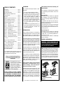
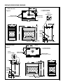
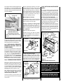
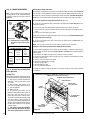
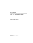
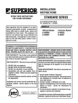
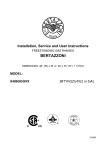
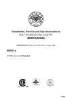
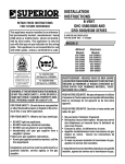
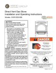
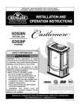
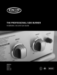
INSTALLATION
INSTRUCTIONS
B-VENT MULTI-OPEN
ELITE® SERIES
This appliance may be installed in an aftermarket permanently located, manufactured home (USA only) or mobile
home, where not prohibited by local codes. This appliance
is only for use with the type of gas indicated on the rating
plate. This appliance is not convertible for use with other
gases, unless a certified kit is used.
In the Commonwealth of Massachusetts & New York:
• Installation must be performed by a licensed plumber or
gas fitter.
See Table of Contents for location of additional New York
& Commonwealth of Massachusetts requirements.
B-VENTED GAS FIREPLACES
P/N 850,025M REV. B 01/2007
MODELS
Millivolt Models
EBVSTNM
EBVPFNM
EBVCRNM
EBVCLNM
EBVSTPM
EBVPFPM
EBVCRPM
EBVCLPM
Electronic Models
EBVSTNE
EBVPFNE
EBVCRNE
EBVCLNE
RETAIN THESE INSTRUCTIONS
FOR FUTURE REFERENCE
WARNING: IF THE INFORMATION IN THIS MANUAL
IS NOT FOLLOWED EXACTLY, A FIRE OR EXPLOSION MAY RESULT CAUSING PROPERTY DAMAGE, PERSONAL INJURY OR LOSS OF LIFE.
FOR YOUR SAFETY: Do not store or use gasoline
or other flammable vapors or liquids in the vicinity of this or any other appliance.
FOR YOUR SAFETY: What to do if you smell gas:
•
•
•
•
DO NOT light any appliance.
DO NOT touch any electrical switches.
DO NOT use any phone in your building.
Immediately call your gas supplier from a
neighbor’s phone. Follow your gas suppliers
instructions.
• If your gas supplier cannot be reached, call the
fire department.
Installation and service must be performed by a
qualified installer, service agency or the gas
supplier.
OTL Report No. 116-F-07A-5
AVERTISSEMENT: ASSUREZ-VOUS DE BIEN SUIVRE
LES INSTRUCTIONS DONNÉ DANS CETTE NOTICE POUR
RÉDUIRE AU MINIMUM LE RISQUE D'INCENDIE OU
POUR ÉVITER TOUT DOMMAGE MATÉRIEL, TOUTE
BLESSURE OU LA MORT.
POUR VOTRE SÉCURITÉ: Ne pas entreposer ni utiliser
d'essence ni d'autre vapeurs ou liquides inflammables
dans le voisinage de cet appareil ou de tout autre
appareil.
POUR VOTRE SÉCURITÉ: Que faire si vous sentez une
odeur de gaz:
• Ne pas tenter d'allumer d'appareil.
• Ne touchez à aucun interrupteur. Ne pas vous servir
des téléphones se trouvant dans le batiment où
vous vous trouvez.
• Evacuez la piéce, le bâtiment ou la zone.
• Appelez immédiatement votre fournisseur de gaz
depuis un voisin. Suivez les instructions du
fournisseur.
• Si vous ne pouvez rejoindre le fournisseur de gaz,
appelez le service dos incendies.
L'installation et service doit être exécuté par un qualifié
installeur, agence de service ou le fournisseur de gaz.
NOTE: DIAGRAMS & ILLUSTRATIONS NOT TO SCALE.
1
PACKAGING
TABLE OF CONTENTS
Packaging ........................................ page
Introduction ..................................... page
2
2
The assembled vented gas fireplace is packaged with:
General Information ......................... page
Massachusetts and New York
2
Requirements ................................ page
Location .......................................... page
2
4
Appliance and Vent Clearances ....... page
Vent Termination Clearances ........... page
4
4
Typical Installation Sequence .......... page
Detailed Installation Steps ............... page
4
5
Step 1. Framing ............................. page
Step 2. Routing Gas Line ............... page
5
5
Step 3. Install the Venting System . page
Fireplace Specifications ................... page
5
6
1 - one log set located within the firebox.
2 - one plastic bag containing the literature
package, which consists of the homeowner's
manual, installation instructions, log placement guide and warranty, 8 (EBVST), 4
(EBVPF, EBVCL and EBVCR) nailing flanges;
plastic bag is located on top of the fireplace.
3 - two hoods (EBVST, EBVCR, EBVCL), or
three hoods (EBVPF) taped to the top of the
fireplace.
4 - one plastic bag of glowing embers, one
plastic bag of decorative volcanic stone and
one bag of vermiculate is located in the
bottom compartment.
Step 4. Field Wiring ....................... page 10
Step 5. Connecting Gas Line .......... page 11
INTRODUCTION
Step 6. Outside Air Kit Installation . page 12
Step 7. Installing Logs ................... page 13
These vented gas fireplaces are designed for
residential applications. They must be installed
with approved type-B, 6 in. double wall vent
pipe systems routed to the outside atmosphere.
Step 8. Checking Unit Operation ..... page 13
Step 9. Installing Glass Enclosure
Panels .......................................... page 13
Step 10. Burner Adjustment ............ page 14
Step 11. Spillage Test and Safety
Limit Switch Operation ................ page 14
Step 12. Hood Installation ............... page 15
Finishing Requirements ................... page 15
Cold Climate Insulation .................... page 15
Gas Conversion Kits .................. page 16
This installation manual will help you achieve a
safe, efficient and dependable installation for
your appliance and vent system.
Please read and understand these
instructions before beginning your
installation.
The millivolt appliances are designed to operate
on either natural or propane gas. A millivolt gas
control valve with piezo ignition system provides
safe, efficient operation. If any optional accessories which require electrical power are being
installed, the electrical power must be provided
at the time of appliance installation.
Electronic appliances are designed to operate
on natural or propane gas. An electronic intermittent pilot ignition system provides safe,
efficient operation. External electrical power is
required to operate these units.
These appliances comply with National Safety
Standards and are tested and listed by OmniTest Laboratories (Report No. 116-F-07A-5) to
ANSI Z21.50 - 2003 (in Canada, CSA 2.22 2003), and CAN/CGA-2.17-M91 in both USA
and Canada, as vented gas fireplaces.
Massachusetts And New York City, NY
Requirements
These appliances are approved for installation
in the following USA locations listed in the
following:
Massachusetts:
Installation of these fireplaces are approved
for installation in the US state of Massachusetts if the following additional requirements
are met• Installation and repair must be done by a
plumber or gas fitter licensed in the Commonwealth of Massachusetts.
• The flexible gas line connector used shall not
exceed 36 inches (92 centimeters) in length.
• The individual manual shut-off must be a Thandle type valve.
New York City, NY:
Installation of these fireplaces are approved
for installation in New Your City in the US state
of New York, if the following additional requirements are met• An outside air kit (FOAK-4 or FOAK-4LD)
must be installed.
GENERAL INFORMATION
WARNING: THESE FIREPLACES ARE
VENTED DECORATIVE GAS APPLIANCES.
DO NOT BURN WOOD OR OTHER MATERIAL IN THESE APPLIANCES.
Note: Installation and repair should be performed by a qualified service person. The appliance should be inspected annually by a qualified professional service technician. More frequent inspections and cleanings may be required due to excessive lint from carpeting,
bedding material, etc. It is imperative that the
control compartment, burners and circulating
air passage ways of the appliance be kept clean.
TYPICAL INSTALLATION
These appliances may be used for bedroom
installations in the United States and are
listed accordingly. These units may not be
installed in bedrooms in Canada.
DO NOT ATTEMPT TO ALTER OR MODIFY
THE CONSTRUCTION OF THE APPLIANCE OR
ITS COMPONENTS. ANY MODIFICATION OR
ALTERATION MAY VOID THE WARRANTY,
CERTIFICATION AND LISTINGS OF THIS UNIT.
Installation must conform to local codes. In the
absence of local codes, installation must comply with the current National Fuel Gas Code,
ANSI Z223.1. (In Canada, the current CAN-1
B149 installation code.) Electrical wiring must
comply with the National Electrical Code ANSI/
NFPA 70 - (latest edition). (In Canada, the
current CSA C22-1 Canadian Electrical Code.)
Offset Venting
Vertical Venting
Figure 1
2
NOTE: DIAGRAMS & ILLUSTRATIONS NOT TO SCALE.
S'assurer que le brùleur et le compartiment des
commandes sont propres. Voir les instructions d'installation et d'utilisation qui
accompagnent l'appareil.
Provide adequate clearances around air openings and adequate accessibility clearance for
service and proper operation. Never obstruct
the front, back and/or side viewing surfaces of
the appliance.
These appliances are designed to operate on
natural or propane gas only. The use of other fuels
or combination of fuels will degrade the performance of this system and may be dangerous.
Millivolt Models Millivolt models come standard with the
manually-modulated gas valve; flame appearance and heat output can be controlled at the gas valve. Input of millivolt
models is shown in the following table:
Millivolt Models
Natural and Propane
Input rate (BTU/H)
Gas Models
Manually-modulated
EBVSTNM, EBVPFNM,
30,000 TO 37,500
EBVSTPM, EBVPFPM,
27,000 TO 34,000
EBVCLNM, EBVCRNM,
28,000 TO 34,000
EBVCLPM, EBVCRPM
27,000 TO 34,000
Electronic Models Electronic models have a fixed rate gas valve.
Input of electronic models is shown in the
following table:
Electronic Models*
Input rate (BTU/H)
Natural Gas Models
Fixed Rate
EBVSTNE, EBVPFNE,
37,500
EBVCLNE, EBVCRNE,
34,000
* See page 16 for Electronic Models conversion from
Natural gas to Propane.
All Models Maximum manifold pressure is 3.5 in. w.c.
(0.87 kPa) for natural gas and 10 in. w.c.
(2.49 kPa) for LP/Propane gas.
Installations at Altitudes of 0 to 4500 ft.Units are tested and approved for elevations
of 0 to 4500 feet (0 to 1372 meters).
Installations at Altitudes above 4500 ft.For elevations above 4500 feet (1372
meters), install the unit according to the
regulations of the local authorities having
jurisdiction and, in the USA, the latest edition
of the National Fuel Gas Code (ANSI Z223.1)
or, in Canada, the latest edition of the
CAN1-B149.1 and .2 codes.
Table 1 shows the units' gas orifice size
for the elevations indicated.
Model
No.
Orifice size
Nat.
Prop.
EBVST
EBVPF
#32
#50
EBVCR
EBVCL
#34
#50
Elevation
Feet (meters)
0-4500
(0-1372)
Table 1
The millivolt appliances are manually controlled
and feature a spark ignitor (piezo) that allows
the appliance's pilot gas to be lit without the use
of matches or batteries. This system will still
function in the event of a power outage.
Do not use these appliances if any part has
been under water. Immediately call a qualified, professional service technician to inspect
the appliance and to replace any parts of the
control system and any gas control which
have been under water.
Ne pas se servir de cet appareil s'il a été plongé
dans l'eau, complètement ou en partie. Appeler
un technicien qualifié pour inspecter l'appareil et
remplacer toute partie du système de contrôle et
toute commande qui ont été plongés dans l'eau.
This appliance may be installed in an aftermarket permanently located, manufactured home (USA only) or mobile home,
where not prohibited by local codes. This
appliance is only for use with the type of
gas indicated on the rating plate. This appliance is not convertible for use with
other gases, unless a certified kit is used.
Cet appareil peut être installé dans un maison
préfabriquée (É.-U. seulement) ou mobile
déjà installée à demeure si les réglements
locaux le permettent.
Cet appareil doit être utilisé uniquement avec
les types de gaz indiqués sur la plaque
signalétique. Ne pas l'utiliser avec d'autres gaz
sauf si un kit de conversion certifié est installé.
Test gage connections are provided on the
front of the millivolt gas control valve (identified IN for the inlet and OUT for the manifold side). A ¹⁄₈" NPT test gage connection is
provided at the inlet and outlet side of
the electronic gas control valve.
Minimum inlet gas pressure to these appliances
is 5.0 inches water column (1.24 kPa) for natural
gas and 11.0 inches water column (2.74 kPa) for
propane for the purpose of input adjustment.
NOTE: DIAGRAMS & ILLUSTRATIONS NOT TO SCALE.
Maximum inlet gas supply pressure to these
appliances is 10.5 inches water column (2.61
kPa) for natural gas and 13.0 inches water
column (3.23 kPa) for propane.
These appliances must be isolated from the gas
supply piping system (by closing their individual
manual shut-off valve) during any pressure testing of the gas supply piping system at test
pressures equal to or less than ¹⁄₂ psig (3.5 kPa).
These appliances and their individual shut-off
valves must be disconnected from the gas supply
piping system during any pressure testing of that
system at pressures in excess of ¹⁄₂ psig (3.5 kPa).
These appliances must not be connected to
a chimney or flue serving a separate solid
fuel burning appliance.
Carbon Monoxide Poisoning: Early signs of
carbon monoxide poisoning are similar to
the flu with headaches, dizziness and/or
nausea. If you have these signs, obtain
fresh air immediately. Turn off the gas
supply to the appliance and have it serviced by a qualified professional, as it may
not be operating correctly.
WARNING: B-VENT APPLIANCES ARE NOT
DESIGNED TO OPERATE IN NEGATIVELY
PRESSURED ENVIRONMENTS (PRESSURE
WITHIN THE HOME IS LESS THAN PRESSURES OUTSIDE). SIGNIFICANT NEGATIVELY PRESSURED ENVIRONMENTS
CAUSED BY WEATHER, HOME DESIGN,
OR OTHER DEVICES MAY IMPACT THE
OPERATION OF THESE APPLIANCES.
NEGATIVE PRESSURES MAY RESULT IN
POOR FLAME APPEARANCE, SOOTING,
DAMAGE TO PROPERTY AND/OR SEVERE
PERSONAL INJURY. DO NOT OPERATE
THESE APPLIANCES IN NEGATIVELY PRESSURED ENVIRONMENTS. PROVIDING ADEQUATE VENTILATION TO THE APPIANCE
FOR COMBUSTION AIR WILL ELIMINATE A
NEGATIVE PRESSURE ENVIRONMENT.
WARNING: FAILURE TO COMPLY WITH
THE INSTALLATION AND OPERATING INSTRUCTIONS PROVIDED IN THIS DOCUMENT WILL RESULT IN AN IMPROPERLY INSTALLED AND OPERATING APPLIANCE, VOIDING ITS WARRANTY. ANY
CHANGE TO THIS APPLIANCE AND/OR
ITS OPERATING CONTROLS IS DANGEROUS. IMPROPER INSTALLATION OR USE
OF THIS APPLIANCE CAN CAUSE SERIOUS INJURY OR DEATH FROM FIRE,
BURNS, EXPLOSION OR CARBON MONOXIDE POISONING.
3
TYPICAL LOCATIONS
Corner - Right
(EBCR-2)
*When See-Through (EBST-2) is
installed with one side flush
with a wall,opposite wall must
not extend beyond either
viewing side of the fireplace.
Corner - Left
(EBCL-2)
**See-Through
(EBST-2)
Bay
(EBBAY)
Peninsula
(EBPF-2)
**When See-Through (EBST-2) is
*See-Through (EBST-2) one side flush with a wall
installed in the middle of a room,
do not extend side walls beyond
either viewing side of the fireplace.
Figure 2
WARNING: CHILDREN AND ADULTS
SHOULD BE ALERTED TO THE HAZARDS
OF HIGH SURFACE TEMPERATURES. USE
CAUTION AROUND THE APPLIANCE TO
AVOID BURNS OR CLOTHING IGNITION.
YOUNG CHILDREN SHOULD BE CAREFULLY SUPERVISED WHEN THEY ARE IN
THE SAME ROOM AS THE APPLIANCE.
WARNING: DO NOT PLACE CLOTHING
OR OTHER FLAMMABLE MATERIALS
ON OR NEAR THIS APPLIANCE.
AVERTISSEMENT: SURVEILLER LES
ENFANTS. GARDER LES VÊTEMENTS,
LES MEUBLES, L'ESSENCE OU AUTRES
LIQUIDES À VAPEUR INFLAMMABLES À
COTE DE L'APPAREIL.
These appliances are equipped with an integral combustion air door and actuator arm.
Combustion air kits are optional.Install as
shown in Step 6 on page 12.
LOCATION
In selecting the location, the aesthetic and functional use of the appliance are primary concerns.
However, vent system routing to the outside
atmosphere and access to the fuel supply are
also important. Consideration should be given to
traffic ways, furniture, draperies, etc., due to high
surface temperatures (Figure 2 ). The location
should also be free of electrical, plumbing or
other heating/air conditioning ducting.
4
The appliance should be mounted on a fully
supported base extending the full width and
depth of the unit. The appliance may be located
on or near conventional construction materials. However, if installed on combustible materials, such as carpeting, vinyl tile, etc., a metal
or wood barrier covering the entire bottom
surface must be used.
APPLIANCE AND VENT CLEARANCES
The appliance is approved with zero clearance to combustible materials on all sides (as
detailed in Table 2), with the following exception: When the unit is installed with one side
flush with a wall, the wall on the other side of
the unit must not extend beyond the front
edge of the unit.
BACK
1/2 in. (13 mm)
0 in. (0 mm) spacers
SIDES
1/2 in. (13 mm)
0 in. (0 mm) spacers
TOP SPACERS
0 in. (0 mm)
FLOOR
0 in. (0 mm)
From Bottom
of Unit to
Ceiling
64 in. (1626 mm)
VENT
1 in. (25.4 mm)
Gas vent caps that are located 8' or more from
a portion of a building which extends at an
angle greater than 45° upward from the horizontal may terminate in accordance with (Figure 3 ), provided that in no case shall any
discharge opening on the cap be less than 2'
(610 mm) horizontally from the roof surface
(National Fuel Gas Code ANSI Z223.1 (NFPA
54) 7.6.2) (CAN/CGA B149).
These instructions should be used as a
guideline and do not supersede local codes
in any way.
Multiple Terminations – These appliances
may vent adjacent to and at the same level
with any other gas appliances (including direct-vent appliances) provided that there is at
least 2 ft. (0.6m) between the proximal edges
of the vent caps. These appliances may be
vented adjacent to a chimney vent servicing a
solid fuel fireplace provided the B-vent cap is
at least 2 ft. (0.6m) away from the nearest
point of the chimney opening.
Note: Venting terminals shall not be recessed
into a wall or siding.
X
12
Roof Pitch is X/12
Minimum Height from Roof
to Lowest Discharge Opening
SERVICE CLEARANCES
VIEWING
SIDES (FRONT, BACK
OR SIDE)
Roof Slope
3 Feet. (0.9 meters)
Table 2
In addition, when the unit is installed in the
middle of a room, the side walls surrounding
the unit must not extend beyond the front or
rear edge of the unit. See Figure 2.
Minimum Height
from Roof to Lowest
Discharge Opening
Feet
Meters
Flat to 6/12
1' 0"
0.3
Over 7/12 to 9/12
2' 0"
0.6
Over 10/12 to 12/12
4' 0"
1.2
Over 13/12 to 16/12
6' 0"
1.8
Over 17/12 to 21/12
8' 0"
2.4
Figure 3
Vertical Vent Termination Clearances
Gas Vent Rule – Gas vent caps are not permitted within 8 feet (2.4 mm) of a vertical wall or
similar obstruction.
NOTE: DIAGRAMS & ILLUSTRATIONS NOT TO SCALE.
TYPICAL INSTALLATION SEQUENCE
The typical sequence of installation follows,
however, each installation is unique resulting in
variations to those described.
See the page numbers references in the following steps for detailed procedures.
Step 1. (page 5) Construct the appliance
framing. Position the appliance within the
framing and secure with nailing brackets.
Step 2. (page 5) Route gas supply line to
appliance location.
Step 3. (page 5) Install the vent system
and exterior termination.
Step 4. (page 10) Field Wiring
a. Millivolt Appliances – The operating control switch is factory installed.
b. Electronic Appliances – Connect 120 Vac
electrical power to the appliance receptacle.
Step 5. (page 11) Make connection to gas
supply.
Step 6. (page 12) Outside Air Kit Installation
Step 7. (page 13) Install the log set, vermiculite and glowing embers.
Step 8. (page 13) Checkout appliance operation.
Step 9. (page 13) Install glass enclosure
panels.
Step 10. (page 14) Burner Adjustment.
Step 11. (page 14) Spillage Test and Safety
Limit Switch Operation.
Step 12. (page 15) Install the hoods.
DETAILED INSTALLATION STEPS
The appliance is shipped with all gas controls
and components installed and pre-wired.
1 - Remove the shipping carton.
2 - Remove the top radiant panel; see Figure 4.
Top Radiant
Panel
Top Bustle
Bottom
Bustle
Control
Compartment
Access Panel
Unit Parts Identification
Figure 4
3- Open the control compartment access
panel, by actuating the spring-loaded magnetic catches securing the panel, gently depressing the outer top corners of the panel
until the catches "pop" the panel free and
allowing it to swing out and down to open. See
Figure 20 on page 12.
4 - Open the latches (located on the left and
right sides of the unit front opening, under the
firebox floor) securing the glass enclosure panel.
Remove the panel by tilting it outward at the
bottom and lifting it up. Set the door aside
protecting it from inadvertent damage. See
Figure 24 on page 13.
If the appliance is to be elevated above floor
level, a solid continuous platform must be
constructed. Headers may be in direct contact
with the appliance top spacers but must not be
supported by them or notched to fit around
them. All construction above the appliance
must be self supporting, DO NOT use the
appliance for structural support.
Side Nailing Flanges
The fireplace should be secured to the framing at
the side(s) and/or rear of the unit using the
factory-provided nailing flanges. Install the nailing flanges - 8 (EBVST), 4 (EBVPF, EBVCL,
EBVCR) - as shown in Figure 5 using the existing
screws. Position the fireplace within the framing. When required, the flanges may be bent 90
degrees by hand or with the assistance of a
hammer. Use wood screws to secure the nailing
flanges to the framing. See Table 2 on page 4 for
clearances of framing members to cabinet parts
in the nailing flange area. The nailing flange itself
is exempt from these clearances.
Floor Nailing Tabs
Secure the fireplace to the floor as shown in
Figure 5.
Step 1. FRAMING
Step 2. ROUTING GAS LINE
Frame these appliances as illustrated in Figures 8 (EBVST), 9 (EBVPF), 10 (EBVCL) or
11 (EBVCR) on pages 6 and 7. All framing
details must allow for a minimum clearance
to combustible framing members as shown
inTable 2 on page 4.
Route a ¹⁄₂" (13 mm) gas line as shown in
Figures 8 (EBVST), 9 (EBVPF), 10 (EBVCL) or
11 (EBVCR) on pages 6 and 7. Gas lines must
be routed, constructed and made of materials
that are in strict accordance with local codes
and regulations.
EBVST SHOWN
(EBVPF - NO NAILING FLANGES ON END WITH GLASS PANEL)
EBVCL SHOWN
(FOR EBVCR VIEW, INTERCHANGE SIDES)
Remove these two screws and use them
when installing the nailing flanges.
All appliances are factory-equipped with a flexible gas line connector and ¹⁄₂ inch shutoff valve.
(See step 5 on page 11).
Step 3. Install the Vent System &
Exterior Termination In the United States, vent installation must
conform with local building codes. In the absence of local codes, vents must be installed in
accordance with the current edition of the
National Fuel Gas Code (ANSI-Z223.1).
In Canada, vent installation must conform
with local building codes. In the absence of
local codes, vents must be installed in accordance with the current edition of the National Standard of Canada CAN/CGA-B149.1
or B149.2 Installation Code.
Nailing
Flanges
Turn tabs down and secure to the floor with
8d nails or other appropriate fasteners on all sides
of the unit which do not have viewing glass panels.
This gas fireplace must be vertically vented
using listed 6 in. type-B, double-walled vent
pipe and a listed vent termination.
Figure 5
NOTE: DIAGRAMS & ILLUSTRATIONS NOT TO SCALE.
5
60 degrees
max.
10 ft.
Minimum
12 ft.
Minimum
Slip the first 6 inch (152 mm) section of BVent over the fireplace flue outlet and secure
with four sheetmetal screws (# 8 or larger),
and install the remainder of the B-Vent to the
outside. Minimum overall height of the vent
system and appliance must be 10' (2.54 m)
vertical - no offset (see Figure 6 ); or 12' (3.7
m) when an offset up to 60 degrees from the
vertical is used - this offset may start at the
fireplace flue collar (see Figure 7 ). The
maximum overall height of the vent system
and appliance should not exceed 40 feet.
Install the B-vent system in accordance with
the vent manufacturer's instructions.
CAUTION: THIS APPLIANCE CANNOT BE
VENTED HORIZONTALLY.
Figure 6
Note: Refer to the vent manufacturers installation instructions for variations of venting techniques. If common venting of several units is contemplated, it should be discussed with an architect and the local Building Department.
Figure 7
Do not place insulation materials within 1 in.
of the gas vent system.
FIREPLACE FRAMING SPECIFICATIONS
EBVST
(See-Through)
EBVPF
(Peninsula)
Minimum Framing
Stud size is 2 x 4
inches (millimeters)
inches (millimeters)
Gas Line
Center of gas line
is 3 in. (76 mm)
up from floor.
Gas Line
Center of gas line
is 3 in. (76 mm)
up from floor.
6¹⁄₄
(159)
41¹⁄₂
(1054)
6¹⁄₄
(159)
*41¹⁄₂
(1054)
22³⁄₄**
(578)
40¹⁄₈
(1019)
*41¹⁄₂
(1054)
22³⁄₄**
(578)
*This dimension can be reduced to 41 inches (1041 mm). This results in 0 in. (0 mm)
clearance between framing and unit framing spacers. (The 41¹⁄₂ in. dimension permits
easier fireplace installation, if unit is installed after framing is erected.)
*This dimension can be reduced to 41 inches (1041 mm). This results in 0 in. (0 mm)
clearance between framing and unit framing spacers. (The 41¹⁄₂ in. dimension permits
easier fireplace installation, if unit is installed after framing is erected.)
**Based on 5/8” drywall. Use 23” for 1/2” drywall.
**Based on 5/8” drywall. Use 23” for 1/2” drywall.
Figure 8
6
Minimum Framing
Stud size is 2 x 4
Figure 9
NOTE: DIAGRAMS & ILLUSTRATIONS NOT TO SCALE.
FIREPLACE FRAMING SPECIFICATIONS CONTINUED
EBVCL (Corner-Left)
Minimum Framing
Stud size is 2 x 4
inches (millimeters)
EBVCR (Corner-Right)
inches (millimeters)
Minimum Framing
Stud size is 2 x 4
Gas Line
Center of gas line
is 3 in. (76 mm)
up from floor.
*41¹⁄₂
(1054)
Gas Line
Center of gas line
is 3 in. (76 mm)
up from floor.
*41¹⁄₂
(1054)
9³⁄₄
(248)
6¹⁄₄
(159)
40¹⁄₈
(1019)
40¹⁄₈
(1019)
24
(610)
Optional Gas Line
Location Center of gas line
is 3 in. (76 mm) up from floor.
*This dimension can be reduced to 41 inches (1041 mm). This results in 0 in. (0 mm)
clearance between framing and unit framing spacers. (The 41¹⁄₂ in. dimension permits easier
fireplace installation, if unit is installed after framing is erected.)
Figure 10
9⁷⁄₈
(251)
24
(610)
*This dimension can be reduced to 41 inches (1041 mm). This results in 0 in. (0 mm)
clearance between framing and unit framing spacers. (The 41¹⁄₂ in. dimension
permits easier fireplace installation, if unit is installed after framing is erected.)
Figure 11
NOTE: DIAGRAMS & ILLUSTRATIONS NOT TO SCALE.
7
FIREPLACE SPECIFICATIONS
EBVST (See-Through)
20¹⁄₁₆
(510)
FINISH WALL BRACKET
(Front and back edge of unit top)
Figure 12
12 (305)
B
A
1/2
(13)
FRAMING SPACERS
(Top and Both Sides)
A - 6 (152) DIA. FLUE OUTLET
B - 8 (203) DIA. FLUE COLLAR
DETAIL OF
FINISH WALL BRACKET
40¹⁄₈
(1019)
TOP VIEW
¹⁄₂ (13)
24
(610)
2³⁄₄
(70)
¹⁄₂ (13)
40¹⁄₈
(1019)
12
(305)
4 (102)
OUTSIDE AIR
SHUTTER
41
(1041)
ELECTRICAL
INLETS
37
(940)
ELECTRICAL
INLETS
GAS INLET
4⁹⁄₁₆
(116)
4⁹⁄₁₆
(116)
3 (76)
6⁷⁄₈
(175)
FRONT VIEW
LEFT SIDE VIEW
6⁷⁄₈
(175)
RIGHT SIDE VIEW
FRAMING SPACERS
(Top and Side)
EBVPF (Peninsula)
Figure 13
3 (76)
CONTROL
COMPARTMENT
ACCESS PANEL
20¹⁄₁₆
(510)
FINISH WALL BRACKET
(Front, back, and left edge of unit top)
GAS INLET
12 (305)
A
B
A - 6 (152) DIA. FLUE OUTLET
B - 8 (203) DIA. FLUE COLLAR
DETAIL OF
FINISH WALL BRACKET
¹⁄₂
(13)
40¹⁄₈
(1019)
¹⁄₂
(13)
TOP VIEW
2³⁄₄
(70)
24
(610)
12
(305)
4 (102)
OUTSIDE AIR
SHUTTER
41
(1041)
37
(940)
ELECTRICAL
INLETS
GAS INLET
4⁹⁄₁₆
(116)
3 (76)
LEFT SIDE VIEW
8
FRONT VIEW
CONTROL COMPARTMENT
ACCESS PANEL
NOTE: DIAGRAMS & ILLUSTRATIONS NOT TO SCALE.
6⁷⁄₈
(175)
RIGHT SIDE VIEW
FIREPLACE SPECIFICATIONS CONTINUED
20¹⁄₁₆
(510)
EBVCL (Corner-Left)
A - 6 (152) DIA. FLUE OUTLET
B - 8 (203) DIA. FLUE COLLAR
Figure 14
12 (305)
B
A
DETAIL OF
FINISH WALL BRACKET
FINISH WALL BRACKET
(Front and left edge of unit top)
¹⁄₂
(13)
FRAMING SPACERS
(Top, Side and Back)
¹⁄₂
(13)
40¹⁄₈
(1019)
TOP VIEW
2³⁄₄
(70)
24
(610)
12
(305)
¹⁄₂
(13)
4 (102)
37
(940)
41
(1041)
OUTSIDE AIR
SHUTTER
ELECTRICAL
INLETS
GAS INLET
4⁹⁄₁₆
(116)
3 (76)
LEFT SIDE VIEW
CONTROL COMPARTMENT
ACCESS PANEL
FRONT VIEW
20¹⁄₁₆
(510)
EBVCR (Corner-Right)
6⁷⁄₈
(175)
RIGHT SIDE VIEW
TOP VIEW
Figure 15
A - 6 (152) DIA. FLUE OUTLET
B - 8 (203) DIA. FLUE COLLAR
12 (305)
DETAIL OF
FINISH WALL BRACKET
B
A
FRAMING SPACERS
(Top, Side and Back)
FINISH WALL BRACKET
(Front and right edge of unit top)
¹⁄₂
(13)
40¹⁄₈
(1019)
¹⁄₂
(13)
12
(305)
2³⁄₄
(70)
24
(610)
4 (102)
41
(1041)
OUTSIDE AIR
SHUTTER
37
(940)
ELECTRICAL
INLETS
GAS INLET
3 (76)
6⁷⁄₈
(175)
LEFT SIDE VIEW
FRONT VIEW
CONTROL COMPARTMENT
ACCESS PANEL
NOTE: DIAGRAMS & ILLUSTRATIONS NOT TO SCALE.
RIGHT SIDE VIEW
9
Step 4. FIELD WIRING
Millivolt Wiring Diagram
Caution: do not connect the optional wall
switch to a 120V power supply.
4. If an optional control switch is installed,
turn the appliance-mounted ON/OFF burner
control switch to the OFF position.
10
LIMIT SWITCH
TH
Note: The supplied 15 feet of 2 conductor
wire has one end of each conductor connected to the gas valve circuit and the other
end of each conductor placed loose inside
the lower compartment of the unit.
TH
TP
1. Appliance-mounted ON/OFF burner control
switch (rocker switch) is factory installed in
the modesty panel. Optional wall-mounted
switch, thermostat, or one of the optional
remote control kits may also be used.
2. If wall-mounted ON/OFF control or thermostat is selected, mount it in a convenient
location on a wall near the fireplace.
3. Wire the control switch within the millivolt
control circuit using the 15 feet of 2 conductor wire supplied with the unit.
White
TP
A. Millivolt Wiring (See Figure 16 )
If any of the original wire as supplied must be replaced,
it must be replaced with Type AWM 105°C – 18 GA. wire.
Thermopile
White
Refer to Section A for millivolt appliances and
Section B for electronic appliances. The gas
valve is set in place and pre-wired at the
factory on both models.
Black
Field Wired
Factory Wired
APPLIANCE-MOUNTED ON/OFF SWITCH
*OPTIONAL WALL-MOUNTED ON/OFF
SWITCH OR OPTIONAL THERMOSTAT
OR OPTIONAL REMOTE RECEIVER
*Turn the appliance-mounted ON/OFF burner control
switch to the OFF position if an optional
control switch is installed.
Schematic Representation Only
Figure 16
B. Electronic Wiring
(also see Figure 18 on page 11 )
Note: The electronic appliance must be connected to the main power supply.
1. Route a 3-wire 120Vac 60Hz 1ph power
supply to the appliance junction box.
2. Open the control compartment access
panel, by actuating the spring-loaded
magnetic catches securing the panel,
gently depressing the outer top corners
of the panel until the catches "pop" the
panel free and allowing it to swing out
and down to open.
NOTE: DIAGRAMS & ILLUSTRATIONS NOT TO SCALE.
3. Remove the bottom control compartment
access panel by compressing the springloaded hinge pin on the left side until it
disengages from the left cabinet panel
hole. Pull the panel away from the fireplace. See Figure 20 on page 12.
4. Remove the modesty panel by pulling the
bottom edge of the modesty panel out of
the locking slots of the cabinet bottom.
Then tilt the top edge at a 45° angel and
lift out. Remove the modesty panel carefully, so that none of the wires become
loose or disconnected.
5. Remove the outlet receptacle by removing the two securing screws. See Figure
17. (The left and right designations used
here are reversed in EBVCR applications.)
6. Install a field-provided strain relief in the
cabinet knockout opening for the protection of the power supply wires.
7. Connect the power supply wires to the
receptacle as shown in Figure 18 on
page 11.
8. Connect the ground supply wire and the
green wire attached to the outlet
receptacle's green ground screw.
9. Appliance-mounted ON/OFF burner control switch (rocker switch) is factory installed in the modesty panel. Optional
wall-mounted switch, thermostat, or one
of the optional remote control kits may
also be used.
FIREBOX BOTTOM
JUNCTION BOX
OUTLET RECEPTACLE
CABINET
RIGHT SIDE
PANEL
10. If wall-mounted ON/OFF switch or thermostat is to be used, mount it in a convenient
location on a wall near the fireplace.
11. If the wall-mounted ON/OFF switch is to be
used, wire it to the the low voltage circuit
as shown in Figure 18.
Electronic Wiring Diagram (Honeywell)
1. If any of the original wire as supplied must be replaced,
1. it must be replaced with Type AWM 105°C – 18 GA.
wire.
2. 120V, 60Hz – Less than 3 amps.
*Leave the ON/OFF switch, which is integral
with the gas valve, in the ON position.
*ON/OFF Switch (Integral
with Gas Valve)
Gas Valve
PILOT
ASSEMBLY
IGNITER
Note: The supplied 15 feet of 2 conductor wire
has one end of each conductor connected to
the gas valve circuit and the other end of each
conductor placed loose inside the lower compartment of the unit.
BK
R
Green
BL
Ground - Green
Neutral - White
120 VAC - Black
White
Black
Junction Box
Tab Intact
Tab
Broken
12. After wiring is complete, reinstall the outlet receptacle; install the field-provided
the metal junction box cover plate; reinstall the modesty panel.
OUTLET RECEPTACLE
BOX SECURING SCREW
EBST-2, EBPF-2
AND EBCL-2 OUTLET RECEPTACLE SHOWN.
EBCR-2 HAS THE OUTLET RECEPTACLE LOCATED IN
THE LEFT CORNER OF THE UNIT
EBBAY OUTLET RECEPTACLE LOCATED IN
THE REAR LEFT CORNER OF THE UNIT
VIEW OF RIGHT BOTTOM CORNER OF UNIT
OUTLET RECEPTACLE INSTALLATION
Figure 17
Note: The gas valve ON/OFF switch is shown in
Figure 18. It is integral with the gas valve and
should be set to the ON position.
IMPORTANT: Ground supply wire must
be connected to the green wire attached
to the outlet receptacle's green ground
screw. See Figure 18 . Failure to do so
will result in a potential safety hazard.
The appliance must be electrically
grounded in accordance with local codes
or, in the absence of local codes, the
National Electrical Code, ANSI/NFPA 70(latest edition). (In Canada, the current
CSA C22-1 Canadian Electrical Code.)
Red
Green
Ground
Screw
Hot
Side of
Receptacle
Neutral
Side of
Receptacle
W
B
Optional
Accessory
Switch
Transf.
120 V.
G
24 V
BL
R
WT
BK
WT
LIMIT SWITCH
APPLIANCE-MOUNTED ON/OFF SWITCH
**OPTIONAL WALL SWITCH
OR OPTIONAL THERMOSTAT
OR OPTIONAL REMOTE
RECEIVER
**Turn the appliance-mounted ON/OFF burner control switch to
the OFF position if an optional control switch is installed.
Factory Wired
Field Wired
Schematic Representation Only
Figure 18
Step 5. CONNECTING GAS LINE
Make gas line connections. All codes require a
shut-off valve mounted in the supply line.
Figure 19 on page 12 illustrates two methods
for connecting the gas supply. The flex-line
method is acceptable in the U.S., however,
Canadian requirements vary depending on locality. Installation must be in compliance with
local codes.
NOTE: DIAGRAMS & ILLUSTRATIONS NOT TO SCALE.
11
Step 6. Outside Air Kits – Optional outside makeup air kits, Model FOAK-4 or FAOK-4LD, may be
used with these appliances. Refer to the installation instructions packaged with the air kits for
specific installation information. If used, the outside air kit must be installed before the fireplace is
framed and enclosed in the finished wall.
Gas Flex Line Connector
³₈" NPT ₂ ³₈
Flare Fitting
Gas
Valve
¹₂" x ³₈" Flare
Shut-Off Valve
³₈ Flex Tubing
Outside air drawn into the fireplace supplies
air to the fire for combustion. Only one outside
air duct is necessary, if installed. See the
Figures on pages 8, 9 and 10 for the location
of the units outside air inlet.
Gas Stub
³₈" Nipple
³₈" Union
³₈" Close Nipple
³₈" Shut-Off Valve
¹₂ x ³₈ "
Reducer
If additional length of duct is necessary, purchase locally available U.L. Class 0 or Class 1
metallic ducting. The duct may extend up to 50'
(15.24 m) in any direction.
Figure 19 - GAS CONNECTION
These appliances are equipped with a gas flex
line for use (where permitted) in connecting the
unit to the gas line. A gas flex line is provided to
aid in attaching the B-vent appliance to the gas
supply. The gas flex line can only be used where
local codes permit. See Figure 19 for flex line
description. The flex line is rated for both natural and propane gas. A manual shut off valve is
also provided with the flex line.
The gas control valve is located in the lower
control compartment. To access the valve
proceed as follows:
1- Open the control compartment access panel,
(Figure 20 ) by actuating the spring-loaded
magnetic catches securing the panel, gently
depressing the outer top corners of the panel
until the catches "pop" the panel free and
allowing it to swing out and down to open.
2- Remove the bottom control compartment
access panel by compressing the springloaded hinge pin on the left side until it
disengages from the left cabinet panel hole.
Pull the panel away from the fireplace. See
Figure 20.
3- Remove the modesty panel by pulling the
bottom edge of the modesty panel out of
the locking slots of the cabinet bottom.
Then tilt the top edge at a 45° angel and
lift out. Remove the modesty panel carefully, so that none of the wires become
loose or disconnected.
The millivolt control valve has a ³⁄₈"
(10 mm) NPT thread inlet port. The electronic
control valve has a ¹⁄₂" (13 mm) NPT thread inlet
port and is fitted with a ¹⁄₂" x ³⁄₈" (13 mm x
10 mm) NPT fitting.
Secure all joints tightly using appropriate
tools and sealing compounds (ensure propane resistant compounds are used in propane applications).
12
Note: When installing the air duct vertically,
DO NOT terminate the duct closer than 3'
below the chimney top.
Hinge
Pin
Piezo
Ignitor
ON/OFF
Switch
Modesty
Panel
Gas Valve
Control
Compartment
Access panel
Modesty Panel
Lock Slot
Figure 20
Turn on gas supply and test for gas leaks using
a soapy water solution. Never use an open
flame to check for leaks.
A. Mix a 50% dish soap, 50% water solution.
B. Light the appliance (refer to the lighting
instructions provided in the Homeowner's Care
and Operation Instructions).
C. Brush all joints and connections with the
soapy water solution to check for leaks. If
bubbles are formed, or gas odor is detected,
turn the gas control knob to the “OFF” position. Either tighten or refasten the leaking
connection and retest as described above.
D. When the gas lines are tested and leak free,
observe the individual tongues of flame on the
burner. Make sure all ports are open and
producing flame evenly across the burner. If
any ports are blocked, or partially blocked,
clean out the ports.
NOTE: DIAGRAMS & ILLUSTRATIONS NOT TO SCALE.
Outside combustion air ducting may be run
upwards or vertically through framing and
ceiling joists, with the hood installed through
an outside wall and 3' (1 m) below the termination. Ducting may also be run downward
through floor Joists and under the home to a
ventilated crawlspace not considered part of
the living area of the home.
Note: Do not terminate outside air kit in attic
space under any circumstances.
CAUTION: NEVER LOCATE INLET WHERE IT
CAN BE BLOCKED BY SHRUBS, SNOW
DRIFTS, ETC. NEVER LOCATE INLET IN GARAGE OR ANY AREA WHERE THERE IS ANOTHER FUEL BURNING APPLIANCE OR PRODUCTS EMITTING COMBUSTIBLE GASES SUCH
AS PAINT, GASOLINE, ETC. IN COLD CLIMATES, IT IS RECOMMENDED THE COMBUSTION AIR DUCT BE INSULATED.
After completing the installation of the optional outside air vent system, the outside air
control lever must be put in service and tested
to ensure proper operation before completing
any enclosure around the firebox. Failure to
do so may result in extensive and costly rework. Before the operation of the vent system
can be tested, the lever securing screw must
be removed. See Figure 21 on page 13.
The hand operated outside air control lever is
located on the right side (EBVST, EBVPF, and
EBVCL) or left side (EBVCR) of the fireplace
opening. See Figure 21 on page 13.
To open the outside air shutter, open the bottom
control access panel, reach into the gap between
the firebox bottom and the modesty panel, and
pull the outside air control lever all the way out.
The outside air shutter should be fully open when
the fireplace is in use and completely closed
when the fireplace is not being used. Closing it
when not in use will prevent outside cold air from
entering the dwelling.
Outside Air Control Lever with Stop Behind
Securing Screw
When first lighting the appliance, it will take
a few minutes for the line to purge itself of
air. Once purging is complete, the pilot and
burner will light and operate as indicated in
the instruction manual. Subsequent lightings
of the appliance will not require such purging. Inspect the pilot flame (remove logs, if
necessary, handling carefully).
Millivolt Appliance Checkout
The pilot flame should be steady and, not lifting
or floating. Flame should be blue in color with
traces of orange at the outer edge.
Outside Air Shutter in the
Closed Position
Control Compartment Access Panel
Outside Air Control Lever
and Securing Screw Location
(EBVST, EBVPF and EBVCR Units Shown)
Figure 21
Operate the actuator through several cycles
including the closed position. Ensuring proper
operation and freedom of movement. Return
the actuator arm to the closed position.
Step 7. INSTALLING LOGS, VERMICULITE,
DECORATIVE VOLCANIC STONE AND
GLOWING EMBERS
The log set is located within the firebox. One
plastic bag of glowing embers, one plastic bag
of decorative volcanic stone and one bag of
vermiculate, is located in the bottom compartment. Refer to the Log Placement Guide for
detailed placement instructions for the log set
and glowing embers. See the Homeowners
Manual for placement instructions of vermiculate, decorative volcanic stone and rockwool.
Step 8. CHECKING APPLIANCE OPERATION
With gas line installed run initial system checkout before closing up the front of the unit.
Follow the pilot lighting instructions provided
in the Homeowner's Care and Operation Instructions. For piezo ignitor location see Figure
20 on page 12 (millivolt appliances only).
The top ³⁄₈" (10 mm) at the pilot generator
(thermopile) and the top ¹⁄₈" min (tip) of the
quick drop out thermocouple should be engulfed in the pilot flame. The flame should
project 1" (25 mm) beyond the hood at all three
ports (Figure 22).
1. Visually inspect the gasket on the backside
of the panels. The gasket surface must be
clean, free of irregularities and seated firmly.
2. Position the glass enclosure panel in front
of the firebox opening at a 45 degree angle and
engage the top flange over the lip at the top of
the firebox opening. See Figure 24.
3. Swing the glass enclosure panel down and
back. Ensure the gasket seats evenly as the
panel draws shut. Engage the Vee-flanges at
the bottom of the panel with the latches; then
close the latches to secure the panel.
4. After installing the front glass enclosure
panel, reinstall the bottom control compartment access panel by inserting the right side
locating pin into the right side cabinet panel
and then the left side spring-loaded pin into
the left side cabinet panel.
Replace logs after pilot inspection.
To light the burner; turn “ON” the modesty
panel mounted ON/OFF switch and rotate the
gas valve control knob counterclockwise to
the “ON” position.
Hood
MILLIVOLT
Lower Compartment Door and Hinge
Modesty Panel
Top Flange
(Glass Enclosure
Panel Frame)
Front Glass
Enclosure Panel
Ignitor Rod
Thermocouple
³⁄₈" Min
(9 mm)
Pilot
Nozzels
Thermopile
Figure 22
Electronic Appliance Checkout
To light the burner, turn ‘ON’ the modesty
panel mounted ON/OFF switch and turn the gas
control switch to the “ON” position. Ensure the
ignitor lights the pilot. The pilot flame should
engulf the flame rod as shown in Figure 23.
Bottom Vee-flanges
(Glass Enclosure
Panel Frame)
Glass
Enclosure
Panel
Latch
Firebox
Floor
EBVST SHOWN
Figure 24 Installing the Glass Enclosure Panel
ELECTRONIC
Proper Flame
Adjustment
Pilot
Nozzle
Note: Lighting instructions may also be found
on the pull out lighting instruction labels
attached to the gas control valve.
To access the label, see the procedure on the
previous page described for accessing the gas
control valve.
Step 9. INSTALLING GLASS ENCLOSURE
PANELS
3/8 To 1/2 Inch
(9 mm to 13 mm)
Ground
Electrode
Flame Rod
Hot Surface
Igniter
Figure 23
NOTE: DIAGRAMS & ILLUSTRATIONS NOT TO SCALE.
WARNING: HANDLE THE GLASS WITH
EXTREME CARE! TEMPERED GLASS IS
SUSCEPTIBLE TO DAMAGE (SCRATCHES,
FOR EXAMPLE) – HANDLE GLASS DOOR
(GLASS ENCLOSURE PANEL) GENTLY
WHILE REINSTALLING IT.
WARNING: NEVER OPERATE THE APPLIANCE WITHOUT THE FRONT GLASS ENCLOSURE PANEL IN PLACE AND SECURE.
13
Step 10. BURNER ADJUSTMENTS
Note - The air shutter for the burner primary air
opening is factory-set. Do not adjust the factoryset position. The factory-set position is shown in
Figure 25.
Burner
Venturi
Tube
*Air Shutter
Opening
Orifice
Manually-Reset Safety Limit Switch
This appliance is equipped with a manually-reset blocked flue safety limit switch. Refer to Figure 26
for its location. If, during appliance operation, the flame goes out (independently of the burner on/
off wall switch), it may be due to the operation of this safety limit switch. First allow the appliance
to cool, then reset the safety switch by pushing the red reset button on the back of the switch.
To access the blocked flue safety limit switch refer to Figure 26:
A - To access the blocked flue safety switch when top radiant panel is not covered with noncombustible material:
1 - Lift up and remove top radiant panel/eyebrow assembly on the control side of unit.
2 - Reach between the cabinet side and the firebox side wall and locate the blocked flue safety
switch.
3 - Push the red reset button on the switch.
The applilance should then relight and remain lit. If this does not occur, turn off the appliance and
call a qualified service technician.
Millivolt Shown
*Note - Do Not Adjust the Factory-Set Position.
The shutter opening is shown in the table
below.
MAIN BURNER
FACTORY SHUTTER SETTING
Propane
Natural Gas
Gas
Models
inches
inches
(mm)
(mm)
EBVST
EBVPF
1/16 (1.5)
7/16 (11)
EBVCR
EBVCL
Figure 25
Step 11. Spillage Test and Safety Limit
Switch Operation
Spillage Test
After appliance installation, perform this spillage
test to verify that proper venting conditions exist:
1 - Place unit in its normally-operated condition, that is, with the glass enclosure panels in place.
2 - Close all doors and windows in the
room. Turn on all exhaust fans in the house.
3 - Light the appliance.
4 - Wait 15 minutes.
5 - To check for venting action, start by
holding a smoke producing device within an
inch of one edge (side edge, not top or
bottom edge) of one glass enclosure panel.
The smoke should be drawn toward the edge
of the glass enclosure panel. Continue the
test by moving the smoke producing device
along the entire length of both side-edges of
the glass door. Repeat the test for all glass
enclosure panels.
6 - If the smoke is not drawn towards the
edges of the glass door turn off the appliance and call a qualified service technican.
14
B - To access the blocked flue safety switch when top radiant panel is covered with noncombustible material:
NOTE - This procedure should only be performed by a qualified service technician.
Important - Turn electrical power off before beginning this procedure.
1 - Lower bottom hinged panel on the control side of the fireplace. Remove the modesty panel
and glass enclosure panel as described on page 5, Steps 3, 4, 5 and 6 under "Detailed Installation
Steps" heading.
2 - Remove the side baffle securing screws (5) and then remove the baffle.
3 - Remove the safety switch bracket securing screws (2), and pull the switch/bracket assembly
through the side panel slot.
4 - Push the red reset button on the switch.
5 - Reinstall the switch/bracket assembly.
6 - Reinstall the side baffle.
7 - Reinstall front glass door.
8 - Raise the bottom hinged panel.
The appliance should then relight and remain lit. If this does not occur, check unit for a blocked
flue condition.
SAFETY SWITCH LOCATION (EBVCL SHOWN) EBVST and EBVPF Safety Switch Location Also as Shown;
EBVCR Location on the Left End of the Fireplace.
FIREBOX SIDE BAFFLE SECURING SCREW
FIREBOX SIDE BAFFLE
MANUALLY-RESET
SAFETY LIMIT SWITCH
FIREBOX
SIDE WALL
TOP RADIANT PANEL
AND EYEBROW
BRACKET
SECURING SCREW
SAFETY SWITCH
Figure 26
NOTE: DIAGRAMS & ILLUSTRATIONS NOT TO SCALE.
CABINET
SIDE WALL
Step 12. HOOD INSTALLATION
COLD CLIMATE INSULATION
All of these appliances must have hoods installed prior to operating on all sides with glass
enclosure panels.
For cold climate installations, seal all cracks
around your appliance with noncombustible
material and wherever cold air could enter the
room. It is especially important to insulate
outside chase cavity between studs and under
floor on which appliance rests, if floor is above
ground level. Gas line holes and other openings should be caulked or stuffed with unfaced
fiberglass insulation. In cold climates, if the
fireplace is being installed on a cement slab, a
sheet of plywood or other raised platform can
be placed underneath to prevent conducting
cold up into the room. It also helps to sheetrock
inside surfaces and tape for maximum air
tightness and caulk firestops.
On all clean face units, slide the hoods into the slots on the lower edges of the radiant panels (Figure 28).
FINISHING REQUIREMENTS
Wall Details
Complete finished interior wall. To install the appliance facing flush with the finished wall, position
framework to accommodate the thickness of the finished wall (Figures 28 ).
A hearth extension is not required with this appliance. If a hearth extension is used, do not block the
control compartment access panel. Any hearth extension used is for appearance only and does not
have to conform to standard hearth extension installation requirements.
Note: Combustible wall finish materials and/or surround materials must not be allowed to
encroach the area defined by the appliance front face (black sheet metal). Never allow
combustible materials to be positioned in front of or overlapping the appliance front face.
See Figures 28.
Non-combustible materials, such as surrounds and other appliance trim, may be installed on the appliance
front face with these exceptions: they must not cover any portion of the glass or louvers; they must not cover
any portion of the top radiant panel and the air gaps surrounding the top radiant panel.
Vertical installation clearances to combustible mantels vary according to the depth of the mantel.
(See Figure 27). Mantels constructed of non-combustible materials may be installed at any height
above the appliance opening; however, do not allow anything to hang below the hood.
Combustible Wall
Framing
1" Min
(25 mm)
Combustible
Wall Framing
Spacer
Combustible
Finished Wall
Materials May
Touch Top of
Unit
MANTEL CLEARANCES
Inches (mm)
This Area Must Remain Clear
of Combustible Materials
Top of Appliance
Radiant panel
Top of Door Frame
12 (305) MANTEL
Hood must be installed as shown.
10 (254) MANTEL
Clean Face Models
8 (203) MANTEL
Figure 28
6 (152) MANTEL
14
(356)
12
(305)
10
(254)
4 (102) MANTEL
8
(203)
6
(152)
2 (51) MANTEL
TOP OF
APPLIANCE
4
(102)
NOTE - Hood shown as positioned
in louvered front model. The hood
position in the flush faced front model
is lower than shown.
*Note - The side walls of mantels may protrude
beyond the front face of the fireplace a maximum
of 5 inches (127mm) at 0 inch clearance to the
sides of the fireplace.
Figure 27
NOTE: DIAGRAMS & ILLUSTRATIONS NOT TO SCALE.
15
GAS CONVERSION KITS
WARNING: THIS CONVERSION KIT SHALL BE
INSTALLED BY A QUALIFIED SERVICE AGENCY IN
ACCORDANCE WITH THE MANUFACTURER'S INSTRUCTIONS AND ALL APPLICABLE CODES AND
REQUIREMENTS OF THE AUTHORIZED AGENCY
HAVING JURISDICTION. IF THE INFORMATION IN
THESE INSTRUCTIONS IS NOT FOLLOWED EXACTLY, A FIRE, EXPLOSION OR PRODUCTION OF
CARBON MONOXIDE MAY RESULT CAUSING
PROPERTY DAMAGE, PERSONAL INJURY OR LOSS
OF LIFE. THE INSTALLATION IS NOT PROPER AND
COMPLETE UNTIL THE OPERATION OF THE CONVERTED APPLIANCE IS CHECKED AS SPECIFIED IN
THE OWNER INSTRUCTIONS SUPPLIED WITH THE
KIT. THE QUALIFIED SERVICE AGENCY PERFORMING THIS INSTALLATION ASSUMES RESPONSIBILITY FOR THIS CONVERSION.
In Canada:
THE CONVERSION SHALL BE CARRIED OUT
IN ACCORDANCE WITH THE REQUIREMENTS
OF THE PROVINCIAL AUTHORITIES HAVING
JURISDICTION AND IN ACCORDANCE WITH
THE REQUIREMENTS OF THE CAN1-B149.1
AND .2 INSTALLATION CODE.
LA CONVERSION DEVRA ÊTRE EFFECTUÉE
CONFORMÉMENT AUX RECOMMANDATIONS
DES AUTORITÉS PROVINCIALES AYANT
JURIDICTION ET CONFORMÉMENT AUX
EXIGENCES DU CODE D'INSTALLATION CAN1B149.1 ET.2.
Gas conversion kits are available to convert
your appliance from the use of one type of gas
to the use of another. These kits contain all the
necessary components needed to complete
the task including labeling that must be affixed
to ensure safe operation.
Kit part numbers are listed here and the following steps detail the conversion procedure.
Step 1. Turn off the gas supply to the appliance.
a. Open the control compartment access panel,
by actuating the spring-loaded magnetic
catches securing the panel, gently depressing the outer top corners of the panel until the
catches "pop" the panel free and allowing it to
swing out and down to open.
16
AVERTISSEMENT: CET ÉQUIPEMENT DE CONVERSION
SERA INSTALLÉ PAR UNE AGENCE QUALIFIÉE DE SERVICE CONFORMÉMENT AUX INSTRUCTIONS DU
FABRICANT ET TOUTES EXIGENCES ET CODES
APPLICABLES DE L'AUTORISÉS AVOIR LA JURIDICTION.
SI L'INFORMATION DANS CETTE INSTRUCTION N'EST
PAS SUIVIE EXACTEMENT, UN FEU, EXPLOSION OU PRODUCTION DE PROTOXYDE DE CARBONE PEUT RÉSULTER
LE DOMMAGES CAUSER DE PROPRIÉTÉ, PERTE OU
BLESSURE PERSONNELLE DE VIE. L'AGENCE QUALIFIÉE
DE SERVICE EST ESPONSABLE DE L'INSTALLATION
PROPRE DE CET ÉQUIPMENT. L'INSTALLATION N'EST
PAS PROPRE ET COMPLÉTE JUSQU'À L'OPÉRATION DE
L'APPAREIL CONVERTI EST CHÉQUE SUIVANT LES
CRITÈRES ÉTABLIS DANS LES INSTRUCTIONS DE
PROPRIÉTAIRE PROVISIONNÉES AVEC L'ÉQUIPEMENT.
b. Remove the bottom control compartment
access panel by compressing the springloaded hinge pin on the left side until it
disengages from the left cabinet panel
hole. Pull the panel away from the fireplace. See Figure 20 on page 12.
c. Remove the modesty panel by pulling the
bottom right corner of the modesty panel
out slightly to disengage the snap-fit feature; lift the modesty panel by the tab on
the panel's right end, pull the right end of
the panel away from the cabinet and then
pull the panel diagonally out of the left side
cabinet panel slots. (In the above procedure, reverse the words "left" and "right"
for EBVCR models). Remove the modesty
panel carefully, so that none of the wires
become loose or disconnected.
d. Locate the latch at the top of the control
compartment. To disengage the latch from
the bottom vee-flange of the glass enclosure panel, reach for the handles located
towards the back of the latch and pull the
handl down toward the front of the unit.
e. Swing the bottom of the door out and raise
it slightly to lift the top flange of the door
frame away from the appliance.
Step 2. Carefully remove the logs. Exercise
care as not to break the logs.
Step 3. Referring to Figure 29 on page 17,
remove the burner.
NOTE: DIAGRAMS & ILLUSTRATIONS NOT TO SCALE.
Natural To Propane Gas Conversion Kit
Models No.
Unit Type
Catalog No.
EBVST
EBVPF
millivolt
H2198
electronic
H2200
Natural To Propane Gas Conversion Kit
Models No.
Unit Type
Catalog No.
EBVCR
EBVCL
millivolt
H2198
electronic
H2200
Propane to Natural Gas Conversion Kit
Model No.
Unit Type
Catalog No.
EBVST
EBVPF
millivolt
H2199
electronic
H2201
Propane to Natural Gas Conversion Kit
Model No.
Unit Type
Catalog No.
EBVCR
EBVCL
millivolt
H2203
electronic
H2205
Inlet Pressure Test Port
I
OFF
ON
CONTROL
PAN BURNER
PSI
IGNITE
Pressure
Regulator
Manifold
Pressure
Test Port
Remove
These
Components
FIREBOX BOTTOM
Slotted
Cap
Figure 30
Spring
Adjusting
Screw
BACK OF FIREPLACE
BURNER POSITIONING
PAN
BURNER
PILOT ASSEMBLY
Figure 29
Millivolt Appliances
Step 6. Refer to Figure 31 and remove the
pilot hood assembly to access the hexed pilot
orifice. Remove and replace the orifice with
the one provided with the kit.
Pilot
Orifice
Figure 31
Step 4. SIT Systems - Refer to Figure 30 and
the instructions provided with the kit. Using a
Torx T20, remove and discard the three pressure regulator mounting screws. Remove the
pressure regulator, spring, poppet, diaphragm
and bushing. Discard all removed components. Ensure the rubber gasket installed on
the back of the replacement pressure regulator
is properly positioned and install the new pressure regulator using the new screws supplied
with the kit. Tighten screws to 25 In. lb. torque.
Electronic Appliances
Step 5. Attach manometer to the manifold side
pressure test fitting and verify manifold pressure reads 3.5 inches water column (0.87 kPa)
for natural gas, and 10.0 inches water column
(2.49 kPa) for propane gas.
Before installing the cap, attach manometer
to the manifold side pressure test fitting and
adjust screw until pressure reads 3.5 inches
water column (0.87 kPa) for natural gas, and
10.0 inches water column (2.49 kPa) for
propane gas.
Step 7. Honeywell Electronic Valves - See
Figure 32 and the instructions provided with
the kit. Remove the slotted cap screw, o-ring,
pressure-regulating adjusting screw and
spring. Retain all parts for possible later use.
Install new components from the kit. Black
cap and red spring for propane gas units.
Silver cap and stainless steel spring fro natural
gas units.
Figure 32
See Figure 33 and replace the pilot orifice as
follows: Remove the ignitor assembly retainer
clip, and carefully remove the ignitor assembly.
Exercise extreme care to prevent damage to
or breakage of the ignitor assembly. Remove
the screw securing the pilot assembly to its
mounting bracket. Back off the flare nut at the
end of the pilot gas line to free the pilot assembly from the gas line. Remove the pilot orifice
and replace it with the one provided with the
conversion kit. Reinstall the pilot assembly by
reversing the steps detailed here.
When reinstalling the ignitor assembly, use
extreme care to prevent damage and breakage. Do not apply any leverage to the ignitor
assembly while restoring the retainer clip to
its original position.
Pilot
Assembly
Pilot
Orifice
Ignitor
Assembly
Flare Nut
Retaining
Clip
Note: If the ignitor is damaged, a replacement kit is available, order Catalog Number
87L54.
Figure 33
NOTE: DIAGRAMS & ILLUSTRATIONS NOT TO SCALE.
17
All Models
Kit Catalog No.
H2199 and H2201
Step 8. (Refer to Figure 29 )
THIS APPLIANCE HAS BEEN CONVERTED TO:
A. Remove the orifice from the manifold
and replace it with the one provided in the
kit. See the following table for orifice
sizes for natural and propane models.
Figure 34 illustrates the orifice.
B. Install the burners as shown in Figure 29.
The primary air opening can be adjusted
by removing the venturi tube air shutter
securing screw and placing it in the other
hole provided nearby. The correct hole
usage for this screw for the gas being
used can be determined by the air shutter
gap indicated in Figure 25 on page 14.
Model
No.
Orifice size
Nat.
Prop.
EBVST
EBVPF
#32
#50
EBVCR
EBVCL
#34
#50
Elevation
Feet
(meters)
0-4500
(0-1372)
NATURAL GAS
INPUT BTU/HR – 37,500
MANIFOLD PRESSURE – 3.5"
ORIFICE SIZE – #32
Kit Catalog No.
H2203 and H2205
THIS APPLIANCE HAS BEEN CONVERTED TO:
NATURAL GAS
INPUT BTU/HR – 34,000
MANIFOLD PRESSURE – 3.5"
ORIFICE SIZE – #34
Kit Catalog No.
H2198 and H2200
THIS APPLIANCE HAS BEEN CONVERTED TO:
PROPANE/LPG
INPUT BTU/HR – 34,000
MANIFOLD PRESSURE – 10.0"
ORIFICE SIZE – #50
Figure 35
Figure 34
18
NOTE: DIAGRAMS & ILLUSTRATIONS NOT TO SCALE.
Step 9. Reassemble the remaining components by reversing the procedures outlined in
the preceding steps. Use pipe joint compound
or Teflon tape on all pipe fittings before installing (ensure propane resistant compounds are
used in propane applications, do not use pipe
joint compounds on flare fittings).
Step 10. Attach the conversion label provided
in the conversion kit to the rating plate on the
appliance. Figure 35 shows all of the labels for
all of the kits covered by this manual as shown
in the tables on page 17. Compare the label
provided in the kit being installed to the appropriate label shown in Figure 35.
Step 11. Turn on the gas supply and test for
leaks as shown in step 5 on page 11.
NOTES:
NOTE: DIAGRAMS & ILLUSTRATIONS NOT TO SCALE.
19
Lennox Hearth Products reserves the right to make changes at any time, without notice, in design,
materials, specifications, prices and also to discontinue colors, styles and products.
Consult your local distributor for fireplace code information.
Printed in U.S.A. © 2004 by LENNOX HEARTH PRODUCTS
20
P/N 850,025M REV. B 01/2007
NOTE: DIAGRAMS & ILLUSTRATIONS NOT TO SCALE.
1110 West Taft Avenue • Orange, CA 92865