1
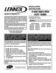
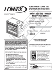
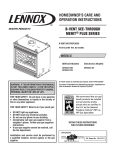
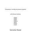
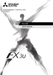
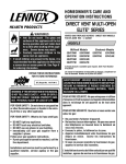
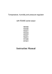
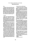
LENNOX HEARTH PRODUCTS
KITS AND ACCESSORIES
750,200M
REV. B 06/2006
DECORATIVE STYLE VIEW™ ARCH PANE SCREEN DOOR KITS
CHARCOAL & SATIN PEWTER
INSTALLATION INSTRUCTIONS FOR DECORATIVE TALL ARCH SCREEN PANEL KITS
FOR USE WITH MPB-35/40/45, MPD-35/40/45, MPB35ST, MPD35ST, EDV-35/40/45, SDDV-35/40, EDVST* & EBVST* GAS FIREPLACES
STYLE VIEW TALL ARCH PANE SCREEN DOOR KITS
CAT#
MODEL
DESCRIPTION
Kit Contents
H3525
TAPD35C
35” Arch Pane, Charcoal
(see Table 2)
H3527
TAPD35SP
4
3
45
35” Arch Pane, Satin Pewter
LENNOX HEARTH PRODUCTS
KITS AND ACCESSORIES
750,200M
REV. NC 12/2005
DECORATIVE STYLE VIEW™ ARCH PANE SCREEN DOOR KITS
CHARCOAL, TEXTURED IRON, SATIN PEWTER & ANTIQUE BRASS
INSTALLATION INSTRUCTIONS FOR DECORATIVE ARCH SCREEN PANEL KIT
FOR USE WITH LMDV-35/40/45, MPD-35/40/45, MPD35ST,
EDV-35/40/45, EDVST & EBVST GAS FIREPLACES
STYLE VIEW ARCH PANE SCREEN DOOR KITS
CAT#
DESCRIPTION
Kit Contents
TAPD35C
35” Arch Pane, Charcoal
(see Table 2)
H3526
TAPD35TI
35” Arch Pane, Textured Iron
H3527
TAPD35SP
35” Arch Pane, Satin Pewter
H3525
MODEL
3
4
LENNOX HEARTH PRODUCTS
KITS AND ACCESSORIES
750,200M
REV. NC 12/2005
H3529
TAPD40C
H3528
40” Arch Pane, Charcoal *
TAPD35AB
35” Arch Pane, Antique Brass
INSTALLATION INSTRUCTIONS FOR DECORATIVE ARCH SCREEN PANEL KIT
FOR USE WITH LMDV-35/40/45, MPD-35/40/45, MPD35ST,
EDV-35/40/45, EDVST & EBVST GAS FIREPLACES
H3525
H3526
H3527
H3528
H3529
TAPD40C
40” Arch Pane, Charcoal
H3531
H3532
H3533
H3534
H3535
H3536
H3537
H3538
H3539
H3540
DESCRIPTION
TAPD35C
ITEM
40” Arch Pane, Textured Iron
1
2
3
(see Table 2)
4
35” Arch Pane, Textured Iron
35” Arch Pane, Satin Pewter
35” Arch Pane, Antique Brass
TAPD40C
40” Arch Pane, Charcoal
TAPD40TI
40” Arch Pane, Textured Iron
TAPD40SP
1
40” Arch Pane, Satin Pewter
45” Arch Pane, Charcoal
Figure 1
45” Arch Pane, Textured Iron
45” Arch Pane, Satin Pewter
45” Arch Pane Doors, Antique Brass
TAPD35EC
Read and understand all instructions and warnings in this document before beginning the installation.
35” Elite Arch Pane, Charcoal
35” Elite Arch Pane, Textured Iron
35” Elite Arch Pane, Satin Pewter
35” Elite Arch Pane, Antique Brass
1 ea.
1 ea.
WARNINGS
Hot! Do not touch! These decorative screen doors
are NOT heat guards. The ceramic glass behind the
screens will be hot during operation and will retain
heat for a while after shutting off the appliance.
Severe burns may result. Carefully supervise
children in the same room as appliance.
DESCRIPTION
Door, Left
Door, Right
1 ea.
Doorframe Assembly
1 ea.
Screen Panel, Lower
1 ea.
Instruction Sheet
These decorative screen doors are offered in four attractive finishes and
fit on the face of the appliance over the glass doorframe. If you encounter
any problems, need clarification of these instructions or are not qualified to
properly install this kit, contact you local distributor or dealer.
40” Arch Pane, Satin Pewter
TAPD40AB
45” Arch Pane, Charcoal
35” Elite Arch Pane, Charcoal
35” Elite Arch Pane, Textured Iron
35” Elite Arch Pane, Satin Pewter
TAPD35EAB
35” Elite Arch Pane, Antique Brass
WARNINGS
Hot! Do not touch! These decorative screen doors
are NOT heat guards. The ceramic glass behind the
screens will be hot during operation and will retain
heat for a while after shutting off the appliance.
Severe burns may result. Carefully supervise
children in the same room as appliance.
KIT CONTENTS
QUANTITY
2
Read and understand all instructions and warnings in this document before beginning the installation.
45” Arch Pane Doors, Antique Brass
TAPD35EC
ITEM
1
Figure 1
45” Arch Pane, Textured Iron
45” Arch Pane, Satin Pewter
TAPD45AB
TAPD35ETI
TAPD35ESP
H3540
• As with any similar heating appliance, surfaces of the
frame and doors including handles can become very
hot. Avoid touching the glass or screen door surfaces
when operating the doors.
• Use care when opening doors . Avoid exerting any
downward pressure on the doors when they are in an
open position. Excessive force can cause the doors to
come loose or be damaged.
• The lower screen panel covering the controls will
become hot during operation. Use care when removing the panel to access the controls and make sure to
place the screen on a surface that is non-combustible
or will not be damaged by high temperatures.
• INSTALL ONLY WHEN THE FIREPLACE IS OFF AND COLD!
NOTE: DIAGRAMS & ILLUSTRATIONS ARE NOT TO SCALE.
40” Arch Pane, Antique Brass
TAPD45C
TAPD45TI
TAPD45SP
H3538
H3539
Table 1
40” Arch Pane, Satin Pewter *
2
40” Arch Pane, Antique Brass
TAPD45C
TAPD45TI
TAPD45SP
TAPD45AB
TAPD35EAB
QUANTITY
4
5
Table 2 - Refer to Figure 1
TOOLS REQUIRED
GENERAL INFORMATION
TAPD40SP
3
Kit Contents
35” Arch Pane, Charcoal
TAPD35TI
TAPD35SP
TAPD35AB
TAPD40AB
TAPD35ETI
TAPD35ESP
KIT CONTENTS
TAPD40TI
None
H3532
H3533
H3534
H3535
H3536
TAPD40SP
MODEL
Table 1
H3530
H3531
H3537
H3531
CHARCOAL, TEXTURED IRON, SATIN PEWTER & ANTIQUE BRASS
STYLE VIEW ARCH PANE SCREEN DOOR KITS
CAT#
H3530
H3529
DECORATIVE STYLE VIEW™ ARCH PANE SCREEN DOOR KITS
DESCRIPTION
1
1 ea.
Door, Left
2
1 ea.
Door, Right
3
1 ea.
Doorframe Assembly
4
1 ea.
Screen Panel, Lower
5
1 ea.
Instruction Sheet
Table 2 - Refer to Figure 1
TOOLS REQUIRED
None
GENERAL INFORMATION
These decorative screen doors are offered in four attractive finishes and
fit on the face of the appliance over the glass doorframe. If you encounter
any problems, need clarification of these instructions or are not qualified to
properly install this kit, contact you local distributor or dealer.
• As with any similar heating appliance, surfaces of the
frame and doors including handles can become very
hot. Avoid touching the glass or screen door surfaces
when operating the doors.
• Use care when opening doors . Avoid exerting any
downward pressure on the doors when they are in an
open position. Excessive force can cause the doors to
come loose or be damaged.
• The lower screen panel covering the controls will
become hot during operation. Use care when removing the panel to access the controls and make sure to
place the screen on a surface that is non-combustible
or will not be damaged by high temperatures.
• INSTALL ONLY WHEN THE FIREPLACE IS OFF AND COLD!
NOTE: DIAGRAMS & ILLUSTRATIONS ARE NOT TO SCALE.
H3533
TAPD45C
45” Arch Pane, Charcoal
H3535
TAPD45SP
45” Arch Pane, Satin Pewter
H3537
TAPD35EC
35” Arch Pane, Charcoal (SDDV-35 & EDV35 only)
H3539
TAPD35ESP
35” Arch Pane, Satin Pewter (SDDV-35 & EDV35 only)
6
1
2
Figure 1
Table 1
WARNINGS
KIT CONTENTS
ITEM
QUANTITY
1
1 ea.
Door, Left
2
1 ea.
Door, Right
3
1 ea.
Doorframe Assembly
4
1 ea.
Lower Compartment Cover
5
1 ea.
Firebox Bottom Cover Panel
6
1 ea.
Instruction Sheet
Hot! Do not touch! The decorative screen doors
and the glass behind the screen doors will
become hot during operation and will retain
heat for a while after shutting off the appliance.
Severe burns may result. Carefully supervise
children in the same room as appliance.
DESCRIPTION
Table 2 - Refer to Figure 1
Read and understand all instructions and warnings in this document before beginning the installation.
TOOLS REQUIRED
5/16” Nutdriver or Socket
1/4” Nutdriver or Socket (for EDVST model only)
GENERAL INFORMATION
These decorative screen doors are offered in two attractive finishes and
fit on the face of the appliance over the glass doorframe. If you encounter
any problems, need clarification of these instructions or are not qualified to
properly install this kit, contact you local distributor or dealer.
* Note: Early revisions of model EDVST and EBVST may also require a magnet
mounting kit, Cat. No. H2110. If the appliance does not have slots described
in Step 5 (to accept the hinge tabs on style view doors), the tabs on the style
view doorframe must be sawed off, then the doorframe will be secured to the
glass door assembly using 4 magnets provided in the H2110 kit.
• These decorative screen doors are NOT heat guards
and are not intended to prevent burns.
• Operate the doors by only using the door handles.
Avoid touching the doorframe, screens, or the glass
enclosure, if the door is opened.
• The lower compartment cover will become hot during
operation of the fireplace. Use care when removing
the panel to access the controls. Handle the compartment cover by grasping the two knobs mounted on the
face of the cover panel.
• Be certain to place the control compartment cover
panel on a surface that is non-combustible or will not
be damaged by high temperatures.
• Use care when opening doors. Avoid exerting any
downward pressure on the doors when they are in an
open position. Excessive force can cause the doors to
come loose or be damaged.
• INSTALL ONLY WHEN THE FIREPLACE IS OFF AND COLD!
NOTE: DIAGRAMS & ILLUSTRATIONS ARE NOT TO SCALE.
a. Open the latch(es) at the bottom of the glass door assembly as shown
in Figure 4 (refer to Homeowners Manual).
INSTALLATION INSTRUCTIONS:
1. Remove Top and Bottom Panels a. Remove the top louvered or radiant panel/hood assembly by pulling
the assembly up and out (see Figure 2). In instances where the radiant
panel is used and it is framed in with tile or other approved material, the
hood must still be removed by firmly pulling it forward until it releases
from the receiving brackets.
b. Remove the bottom louvered or radiant panel/hood assembly (refer to
Homeowner’s Care and Operation Manual).
b. Adjust glass door so that it is evenly spaced and aligned to the fireplace
chassis on both sides. See Figure 4.
c. Fasten the latch(es). Ensure that the latch(es) are engaged with the
door’s vee-flange and fully closed. See Figure 4.
Top Flange on Glass Door
Glass Door
Remove Trim Panels
as shown. The trim
panels will be either
Louvered Panels or
Radiant Panels.
Some models will have a
modesty panel in the control
compartment (in front of
the valve). The appearance
will vary from the example
shown below.
Modesty Panel
Bottom Vee-flange Glass Door
Radiant
Panels
Firebox Floor
Glass Door Latch
Louvered
Panels
Figure 4 - GLASS DOOR ADJUSTMENT
Figure 2 - Remove Top Panel
c. Remove Bustles - Some models have bustles (as shown in Figure 3)
which must be removed. If applicable, remove the top and bottom bustle
by lifting them up and out.
3. Install Firebox Bottom Cover Panel - For Models EDV-35/40/45, see
Figure 5a. For Model EDVST see Figure 5b.
For EDV-35/40/45 Models
Only Some Models
Have Bustles
Bustles
Lift Bustles Up
And Off
Figure 3 - Remove Bustles
2. Align Glass Door (see Figure 4) - Ensure the glass door assembly on
the fireplace is properly aligned as follows:
Note: Units with Modesty Panels - Remove the modesty panel,
if necessary, as follows: Lift the modesty panel by the tab on the
panel’s right end, pull the right end of the panel away from cabinet
and then pull the panel diagonally out of the corner post slots on
the left side of the unit. Remove the modesty panel carefully, so
that none of the wires become loose or disconnected.
2
Step 1 - Remove 2 firebox bottom screws.
Screw
Step 2 - Install the Firebox Bottom Cover Panel (#5 in Figure 1) using the
existing screws that were removed. The top two holes on the panel align to
corresponding holes on fireplace.
Figure 5a - Install Firebox Cover
NOTE: DIAGRAMS & ILLUSTRATIONS ARE NOT TO SCALE.
For EDVST Model Only
Adjust Doorframe Bracket
Locate the doorframe
bracket on the lower front
of the doorframe and lock
it behind the cabinet
bottom flange as
shown here.
Bracket
Screw
Cover
Doorframe
Bracket
Step 1 - Remove the
two #8 screws from
the bracket screw
cover on both sides.
Step 2 - Remove the
two #10 screws from
the firebox bottom
on both sides (save
screws).
#8
Screw
Figure 7
7. Remove the screen doors from packaging. Install them by aligning
hinge pins on the doors with the hinge holes on the doorframe and
slide down (see instructions in Figure 8). Ensure the hinge pins are
fully seated onto the shoulders of the hinge holes.
#10 Screw
Step 3 - Install the Firebox Bottom Cover Panel (#5 in Figure 1) using the
existing #10 screws. The bottom two holes on the cover panel align to corresponding two holes on firebox bottom.
Align hinge pins on the
doors with the hinge holes
on the doorframe and slide
down as shown.
Figure 5b - Install Firebox Cover
4. For EDV, EDVST & EBVST models, reinstall modesty panel, ensuring all
wires are securely connected.
5. Install Doorframe (see Figure 6) - Remove the arched doorframe
from packaging. Position the top of the doorframe above the top of the
glass doorframe (centered and approximately 1” above the top of the
glass doorframe). Slide down so that the hooks catch on the back of
the doorframe slide between the sides of the glass door and the corner
posts engaging into existing slots on fireplace.
Firebox
Hinge Pin
Doorframe
Left
Corner
Post
Right
Corner
Post
Firebox
Figure 6 - INSTALL DOORFRAME
6. Place the doorframe bracket in the locked position as shown in Figure 7.
Figure 8
NOTE: DIAGRAMS & ILLUSTRATIONS ARE NOT TO SCALE.
3
8. Light the appliance following instrutions on lighting label in control
compartment or see lighting instructions in Homeowner’s Care and
Operation Manual provided with appliance.
Note: Ensure that the latch(es) below the door are engaged with the
door’s vee-flange and fully closed before operating the fireplace.
9. Install the lower compartment cover per instructions in Figure 9.
Figure 10 - CLOSE BOTH DOORS
Lower Compartment Cover
Knobs
Place the lower compartment cover hook
behind the glass doorframe bottom flange.
Figure 9 - INSTALL LOWER COMPARTMENT COVER
10. Re-install the top louvered or radiant panel/hood assemblies.
11. Close both doors as shown in Figures 9 & 10.
Figure 11 - COMPLETED INSTALLATION
NOTE: DIAGRAMS & ILLUSTRATIONS ARE NOT TO SCALE.
Lennox Hearth Products reserves the right to make changes at any time, without notice, in design,
materials, specifications, prices and the discontinuance of colors, styles and products. Consult your
local distributor for fireplace code information.
Printed in U.S.A. © LENNOX HEARTH PRODUCTS 2006
4
P/N 750,200M REV. B 06/2006
NOTE: DIAGRAMS & ILLUSTRATIONS ARE NOT TO SCALE.
1110 West Taft Avenue • Orange, CA 92865