Download manual

Transcript
NetBeacon Element Management Software Installation
and User’s Guide
Version 3.4.0
© 1999-2003 Metrobility Optical Systems, Inc.
All Rights Reserved.
Printed in USA.
This publication is protected by the copyright laws of the United States and other countries, with all rights
reserved. No part of this publication may be reproduced, stored in a retrieval system, translated, transcribed, or
transmitted, in any form, or by any means, manual, electric, electronic, electromagnetic, mechanical, chemical,
optical or otherwise, without prior explicit written permission of Metrobility Optical Systems, Inc.
Lancast, the Lancast logo, and “the twister” are registered trademarks; Metrobility Optical Systems, the Metrobility
Optical Systems logo, AutoTwister, MicroChassis, NetBeacon, WebBeacon, “twister” and “redundant twister” are
trademarks of Metrobility Optical Systems, Inc. Java, Sun, Sun Microsystems, and Solaris are trademarks or
registered trademarks of Sun Microsystems, Inc. in the U.S. and other countries. All other trademarks are the
property of their respective owners.
“redundant twister” technology is a patent of Metrobility Optical Systems, Inc.
The information contained in this publication is accurate as of its publication date; such information is subject to
change without notice. Metrobility Optical Systems, Inc. is not responsible for any inadvertent errors.
ii
NetBeacon Management Software ~ Installation and User's Guide
Contents
CONTENTS
III
ABOUT THIS GUIDE ................................................................................................................................................. VII
DOCUMENT CONVENTIONS ..................................................................................................................................... VII
RELATED DOCUMENTS ............................................................................................................................................ VII
USING THE MOUSE ................................................................................................................................................... IX
TECHNICAL SUPPORT ............................................................................................................................................... IX
CHAPTER 1. GETTING STARTED
1
WHAT IS NETBEACON? ..............................................................................................................................................1
FEATURES AND BENEFITS ...........................................................................................................................................2
SYSTEM REQUIREMENTS ............................................................................................................................................2
Client/Server Specifications with Database Plugin ...............................................................................................2
NETBEACON CD CONTENTS ......................................................................................................................................3
INSTALLING THE JAVA RUNTIME ENVIRONMENT .......................................................................................................4
Sun Solaris Installation ..........................................................................................................................................4
HP-UX Installation ................................................................................................................................................5
Red Hat Linux Installation.....................................................................................................................................5
Windows Installation.............................................................................................................................................6
INSTALLING THE NETBEACON SOFTWARE .................................................................................................................7
UNIX/Linux Installation........................................................................................................................................7
Windows Installation.............................................................................................................................................8
UPGRADING NETBEACON.........................................................................................................................................14
VIEWING THE INSTALLATION ERROR LOG ................................................................................................................15
UNINSTALLING THE NETBEACON SOFTWARE ..........................................................................................................15
UNIX Uninstall ...................................................................................................................................................15
Windows Uninstall ..............................................................................................................................................16
WHAT’S NEXT? ........................................................................................................................................................17
CHAPTER 2. NETBEACON BASICS
19
STARTING NETBEACON FROM WINDOWS .................................................................................................................19
Opening the NetBeacon Server Application........................................................................................................19
Opening the NetBeacon Client Application ........................................................................................................20
STARTING NETBEACON FROM LINUX .......................................................................................................................20
STARTING NETBEACON FROM SUN SOLARIS ANDHP-UX............................................................................................21
HP OpenView Network Node Manager ..............................................................................................................21
EXITING NETBEACON ..............................................................................................................................................23
Closing the NetBeacon Client Application..........................................................................................................23
Closing the NetBeacon Server.............................................................................................................................24
CHECKING THE NETBEACON VERSION NUMBER ......................................................................................................25
LEARNING ABOUT THE NETBEACON WINDOW .........................................................................................................26
Resizing the Windows and Dialog Boxes............................................................................................................26
Activity Indicator.................................................................................................................................................27
Trap Alerts...........................................................................................................................................................27
ToolTips ..............................................................................................................................................................27
Chassis View .......................................................................................................................................................27
Devices List .........................................................................................................................................................28
Expanding and Collapsing the Devices List ....................................................................................................29
Fields and Folders................................................................................................................................................29
Shortcut Keys ......................................................................................................................................................30
NetBeacon Management Software ~ Installation and User's Guide
iii
Menu Bar .............................................................................................................................................................31
File Menu.........................................................................................................................................................31
Edit Menu ........................................................................................................................................................31
View Menu ......................................................................................................................................................32
Device Menu ...................................................................................................................................................33
Help Menu .......................................................................................................................................................33
Toolbar ................................................................................................................................................................34
CHAPTER 3. NETBEACON SETUP
35
ADDING A DEVICE THROUGH NETBEACON ..............................................................................................................35
ADDING DEVICES FROM HP OPENVIEW NETWORK NODE MANAGER (NNM) .........................................................36
SELECTING A DEVICE ...............................................................................................................................................36
UNMANAGING A DEVICE ..........................................................................................................................................37
DELETING A DEVICE.................................................................................................................................................37
RESETTING A DEVICE ...............................................................................................................................................38
PINGING A DEVICE ...................................................................................................................................................39
OPENING A TELNET SESSION ....................................................................................................................................39
DOWNLOADING SOFTWARE TO A DEVICE.................................................................................................................40
CHANGING THE DATE AND TIME ..............................................................................................................................42
CUSTOMIZING YOUR DISPLAY ..................................................................................................................................43
Resizing the Chassis View...................................................................................................................................43
Showing Remote Access Line Cards...............................................................................................................43
Showing ToolTips ...............................................................................................................................................44
Changing the Appearance of your Tables............................................................................................................44
Changing the Look & Feel of your Display ........................................................................................................45
Selecting a Temperature Scale.............................................................................................................................45
Refreshing the NetBeacon Window ....................................................................................................................45
PRINTING NETBEACON REPORTS .............................................................................................................................46
Setting Up Pages..................................................................................................................................................46
SETTING USER PREFERENCES ...................................................................................................................................46
Saving a User Profile...........................................................................................................................................47
Renaming a User Profile......................................................................................................................................47
Creating a New User Profile................................................................................................................................48
Opening a User Profile ........................................................................................................................................48
Deleting a User Profile ........................................................................................................................................49
Setting Your Password ........................................................................................................................................49
VIEWING NETBEACON LICENSE INFORMATION ........................................................................................................50
Updating the NetBeacon License ........................................................................................................................50
CONFIGURING THE DATABASE .................................................................................................................................51
Adding a Device for Database Management .......................................................................................................52
Updating the Database Devices List....................................................................................................................52
Removing Database Devices ...............................................................................................................................53
Logging Data .......................................................................................................................................................53
Creating Database Archives ................................................................................................................................54
CHAPTER 4. MANAGING THE DEVICES
55
DISPLAYING DEVICE INFORMATION .........................................................................................................................55
CONFIGURING A DEVICE ..........................................................................................................................................56
MONITORING THE CHASSIS ......................................................................................................................................58
Displaying Chassis Information ..........................................................................................................................59
Displaying Temperature and Power Supply Information ....................................................................................60
RECEIVING TRAPS ....................................................................................................................................................62
Monitoring Traps.................................................................................................................................................62
Displaying the Trap Legend ................................................................................................................................63
Filtering Traps .....................................................................................................................................................64
iv
NetBeacon Management Software ~ Installation and User's Guide
MANAGING TRAPS ...................................................................................................................................................65
Displaying the Trap Management Table .............................................................................................................65
Adding a New Trap Manager ..............................................................................................................................65
Reconfiguring a Trap Manager............................................................................................................................66
Deleting a Trap Manager .....................................................................................................................................67
SENDING E-MAIL NOTIFICATIONS ...............................................................................................................................68
Configuring E-mail Notifications ........................................................................................................................68
Adding E-mail Notifications for Multiple Devices .........................................................................................70
Editing an E-mail Notice .....................................................................................................................................70
Sending a Test E-mail Notice ..............................................................................................................................71
Deleting an E-mail Notice Recipient ...................................................................................................................71
CHAPTER 5. CONFIGURING MODULES AND PORTS
73
DISPLAYING MODULE INFORMATION .......................................................................................................................73
Changing a Module Name and Asset ID .............................................................................................................76
Displaying Management Module Information.....................................................................................................78
Displaying a Remote Access Line Card or Access ONU Information ................................................................79
CONFIGURING A CONVERTER ...................................................................................................................................80
Displaying Converter Information.......................................................................................................................81
Assigning a Converter Name...............................................................................................................................81
Applying Link Loss Carry Forward.....................................................................................................................82
Applying Copper Loss Carry Forward ................................................................................................................83
Configuring the Redundant Interface Line Card .................................................................................................83
Dynamic Recovery Mode ................................................................................................................................84
Applying SONAR ...........................................................................................................................................84
Select A/B Mode .............................................................................................................................................85
Configuring the 10/100Mbps Line Card..............................................................................................................86
Link Loss Carry Forward and Full-Duplex Flow Control ...............................................................................86
Backpressure (Half-Duplex Flow Control)......................................................................................................87
Auto-Recovery ................................................................................................................................................87
Managing the Chassis Stacking Line Card ..........................................................................................................88
Port Duplex, and Full and Half Duplex Flow Control.....................................................................................89
Displaying Access Line Card Details ..................................................................................................................90
Applying Write-Protection ..................................................................................................................................91
CONFIGURING THE PORTS ........................................................................................................................................91
Displaying Port Details........................................................................................................................................91
Displaying Management Module Statistics .........................................................................................................92
Displaying RMON Statistics ...............................................................................................................................93
Viewing TDM Information..................................................................................................................................94
Changing the Port Name......................................................................................................................................94
Applying Link Loss Return .................................................................................................................................95
Configuring the 10/100Mbps Ports .....................................................................................................................96
Configuring the R133 Ports .................................................................................................................................97
Configuring the Access Line Card Ports .............................................................................................................98
Displaying Port Statistics...............................................................................................................................100
Viewing Data History Graphs .......................................................................................................................101
Provisioning Bandwidth ................................................................................................................................102
Configuring the T1/E1 Ports..............................................................................................................................103
Selecting the Line Code and Line Buildout...................................................................................................104
Setting BERT 511, Remote Loopback, and Far End Fault............................................................................104
Configuring the T3/E3 Ports..............................................................................................................................104
Setting the T3 Line Buildout .........................................................................................................................106
APPENDIX A. PERSISTENCE DATA
107
THE DATABASE PERSISTENCE FILE ........................................................................................................................107
NetBeacon Management Software ~ Installation and User's Guide
v
APPENDIX B. DATABASE ARCHIVES
109
ARCHIVE FILES.......................................................................................................................................................109
ARCHIVE FILE FORMATS ........................................................................................................................................110
LOCATING ARCHIVE FILES .....................................................................................................................................110
CHANGING ARCHIVE FILE DEFAULT SETTINGS ......................................................................................................110
DATABASE ARCHIVE DETAILS ...............................................................................................................................111
TableCreate.sql ..................................................................................................................................................111
COPPERPORTSTATS......................................................................................................................................112
FIBERPORTSTATS .........................................................................................................................................112
MODULESTATS..............................................................................................................................................113
CHASSISSTATS...............................................................................................................................................113
UTC TIME CONVERSION ........................................................................................................................................114
Conversion Examples and Hints........................................................................................................................114
Perl Example .................................................................................................................................................114
C Example .....................................................................................................................................................114
GRAPHING GRANULARITY ......................................................................................................................................115
APPENDIX C. DOWNLOAD ERROR MESSAGES
117
APPENDIX D. HP NNM CUSTOMIZATION
119
HP NNM INSTALLATION .......................................................................................................................................119
ENABLE METROBILITY CUSTOMIZATION ...............................................................................................................119
DETAILS OF TRAPD.CONF CHANGES .......................................................................................................................120
APPENDIX E. DISCONTINUED PRODUCT SUPPORT
125
MANAGED FIXED PORT CHASSIS ............................................................................................................................125
PERSISTENCE DATA FOR A FIXED PORT CHASSIS ...................................................................................................126
APPENDIX F. NETBEACON WARRANTY STATEMENT
127
APPENDIX G. PRODUCT SAFETY AND COMPLIANCE STATEMENTS
129
vi
NetBeacon Management Software ~ Installation and User's Guide
About this Guide
The NetBeacon Element Management Software Installation and User's Guide
provides network managers and system administrators with information about how to
configure and manage any Metrobility chassis-based system and related cards.
The reader of this document should be knowledgeable about network devices, device
configuration, network management, and Windows or UNIX environments. The user is
assumed to be a network administrator or manager with an understanding of network
operations.
Document Conventions
The following conventions are used in this guide.
Bold
Indicates a menu option that you choose, a command that you type, or a command
button that you click.
Italics
Indicates a variable for which you provide a value or the title of a document.
Courier
Indicates a message, directory, or filename.
Underline
Indicates a hyperlink. Hyperlinks provide cross-references to other information that
is helpful when performing a task.
SMALL CAPS
Indicates a key on the keyboard that you press. For example: Press the SHIFT key.
Tip
Information that is helpful when performing some activity.
Important
Information that is critical to your understanding of how the product works.
Related Documents
The following documents are additional resources that provide useful information regarding
any Radiance or Lancast chassis and cards, including installation and configuration
guidelines. All Metrobility manuals can be found on our website, www.metrobility.com.
Intelligent 7500 Chassis ~ Installation and User Guide
Radiance R5000 Central Service Platform ~ Installation and User Guide
Radiance R1000 Premise Service Platform ~ Installation and User Guide
Radiance R400 Premise Service Platform ~ Installation and User Guide
Intelligent MicroChassis 7500 ~ Installation and User Guide
Provides detailed chassis and power supply installation instructions and specifications, and
management card setup information.
Intelligent 7500 Modules ~ Quick Reference
Intelligent 7500 7133 Modules ~ Quick Start Guide
NetBeacon Management Software ~ Installation and User's Guide
vii
Contains installation instructions, specifications, switch settings, and connections, in a fast
reference format.
Radiance 10Mbps Single Interface Line Cards ~ Installation and User Guide
Radiance 100Mbps Single Interface Line Cards ~ Installation and User Guide
Contains installation instructions, specifications, switch settings, and connections for the 10
and 100Mbps cards, including the feature-rich R133 line cards.
Intelligent 7500 “redundant twister” ~ Installation & User Guide
Radiance 10Mbps Redundant Interface Line Cards ~ Installation & User Guide
Radiance 100Mbps Redundant Interface Line Cards ~ Installation & User Guide
Radiance 1000Mbps Redundant Interface Line Cards ~ Installation & User Guide
Provides details on how to install, configure, and operate the 10Mbps, 100Mbps and
1000Mbps redundant interface cards. Also includes technical specifications.
Intelligent 7500 10/100 AutoTwister ~ Installation & User Guide
Radiance 10/100Mbps Interface Line Cards ~ Installation & User Guide
Contains information on the installation, configuration, network specifications, and operation
of the 10/100Mbps cards.
Intelligent 7500 “twister” 7131 Optical Extender ~ Installation & User Guide
Contains details on how to install, configure switch settings, and operate the optical
extender module.
Intelligent 7500 Gigabit “twister” and SONET “twister” ~ Installation & User Guide
Radiance Gigabit Single Interface Line Cards ~ Installation & User Guide
Radiance SONET Single Interface Line Cards ~ Installation & User Guide
Provides installation and operational guidelines for the 1000Mbps, OC-3/STM-1 and OC12/STM-4 cards.
Radiance Access Line Cards ~ Installation & User Guide
Provides details on how to install, configure, and operate the 100Mbps access line cards.
Also includes technical specifications.
Radiance 10/100Mbps Access Optical Network Unit ~ Installation & User Guide
Provides details on how to install, configure, operate and monitor the 10/100Mbps access
optical network unit. Also includes troubleshooting information and technical specifications.
Radiance T1/E1 Single Interface Line Cards ~ Installation & User Guide
Contains information on the installation, configuration, technical specifications, and
operation the T1/E1 line cards.
viii NetBeacon Management Software ~ Installation and User's Guide
Radiance T3/E3 Single Interface Line Cards ~ Installation & User Guide
Contains information on the installation, configuration, specifications, and operation the
T3/E3 line cards.
Radiance Chassis Stacking Line Card ~ Installation & User Guide
Provides information on the installation, operation and management of the 10/100Mbps TX
four-port chassis stacking line card. Also includes an example of how to configure a stack of
four chassis using the card.
Command Line Interface ~ Reference Guide
Contains a complete list of the console commands to configure and manage any Metrobility
chassis, as well as instructions on how to set up the management card.
Using the Mouse
Always use the left mouse button when instructed to “click” a command button or choose a
menu option, unless you are instructed to “right-click”. If you have reversed the functions of
the left and right buttons, use the alternate button when following these procedures. See
your platform documentation for further instructions on using your mouse.
Technical Support
Before contacting Technical Support, please make sure you have the following information:
•
NetBeacon software version number
•
Java Runtime Environment (JRE) version number
•
Version of software on the management card
•
Management station hardware specifications (RAM, operating system, and CPU)
Refer to Checking the NetBeacon Version Number.
Notify Metrobility Technical Support via e-mail by contacting
[email protected] or by calling 1.877.526.2278, from 8 AM to 7 PM (EST).
You can also fax Metrobility Optical Systems, Inc. at 1.603.594.2887.
NetBeacon Management Software ~ Installation and User's Guide
ix
Chapter 1. Getting Started
What is NetBeacon?
The NetBeacon management software is a Java application that helps network administrators configure and manage any Radiance or Lancast device. NetBeacon runs under
various Microsoft Windows and UNIX platforms. It also can be integrated with and
launched from HP OpenView Network Node Manager. This version of NetBeacon has been
tested on the following platforms:
•
Windows 2000
• Windows NT 4.0
• Windows XP Professional
•
HP-UX 11.00
• Sun Solaris 8
• Red Hat Linux 7.3
A Radiance or Lancast device is a chassis with slots for one or more manageable line cards
(modules) and a management card. The following illustration shows an example of an
Intelligent 7500 chassis with 12 slots containing several cards.
Lancast Intelligent 7500 Chassis
Intelligent
“twister”
Management
Card
Power
Supplies
Metrobility media converters translate information that enables differing network segments
to be integrated (e.g., from copper to fiber, singlemode to multimode, or Ethernet to Fast
Ethernet). Modules are the replaceable cards installed into the chassis by the user.
The management card provides an interface between the system hardware (chassis and
cards) and NetBeacon.
Connected through the backplane to the modules in the chassis, the management card
reports on the status and configuration of individual boards. The network administrator can
view this status information and control the device configuration through NetBeacon. The
management card, together with NetBeacon, provides the network administrator with the
information necessary to achieve efficient operation.
NetBeacon Management Software ~ Installation and User's Guide
1
Features and Benefits
NetBeacon provides an efficient, user-friendly way to configure and manage all of the
devices installed on a single network or on a series of networks. You can use NetBeacon as
an alternative to the command line interface typically used to configure and operate
network devices. NetBeacon provides an intuitive graphical display of each chassis and its
cards, along with real-time status information on their operation. Management and
operational tasks include the following:
•
Displaying Device Information
•
Configuring a Device
•
Monitoring the Chassis
•
Pinging a Device
•
Opening a Telnet Session
•
Downloading Software to a Device
•
Configuring the Database
•
Sending E-mail Notifications
•
Displaying Module Information
•
Configuring a Converter
•
Displaying Access Line Card Details
System Requirements
Your management hardware must meet the following minimum requirements.
Platform
CPU
Memory
Disk Space
JRE
Windows
750 MHz
256 MB
20 MB for NetBeacon; 17 MB for JRE
Sun JRE 1.4.1
Red Hat Linux
750 MHz
256 MB
20 MB for NetBeacon; 40 MB for JRE
Sun JRE 1.4.1
Sun Solaris
200 MHz
64 MB
20 MB for NetBeacon; 41 MB for JRE
Sun JRE 1.4.1
HP-UX 11.00
200 MHz
64 MB
20 MB for NetBeacon; 56 MB for JRE
HP-UX JRE 1.4.1
Client/Server Specifications with Database Plugin
If you are installing the database version of NetBeacon, the server application must be
installed on a dedicated workstation with the following minimum system requirements:
2
NetBeacon Management Software ~ Installation and User's Guide
Platform
CPU
Memory
Disk Space
Windows or Red Hat Linux
750 MHz
512 MB (server)
256 MB (client)
18 GB (server)
15 GB (client)
Sun Solaris
450 MHz
512 MB
18 GB
HP-UX 11.00 PA-8600
552 MHz
512 MB
18 GB
The NetBeacon client application must be installed on a separate machine with the minimum
requirements listed above.
Important:
When using the database plugin, the client and server applications must be
installed on two separate machines.
Each NetBeacon server can register up to ten clients.
Additional software for Microsoft Windows, Sun Solaris, HP-UX, and Red Hat Linux
may include:
•
Adobe Acrobat Reader for online viewing of this guide
•
HP OpenView Network Node Manager
NetBeacon CD Contents
The NetBeacon CD contains the following five folders.
Folder
Contents
NetBeacon
The NetBeacon application files, the Java Runtime Environment, Release Notes. The
files are separated into Unix and Windows versions.
Firmware
Latest management card firmware (including boot code), and Release Notes.
Manuals
The documentation for installing and configuring various modules and this guide in
Adobe Acrobat format (PDF). Refer to the Utilities folder for the latest version of the
Adobe Acrobat Reader.
For a complete list of documents available for reference, see Related Documents.
MIBs
Management Information Base (MIB) for use with other network management
software, such as HP OpenView. MIB file load order.
Utilities
The latest version of Adobe Acrobat Reader, along with the HP OpenView Network
Node Manager configuration scripts.
NetBeacon Management Software ~ Installation and User's Guide
3
Installing the Java Runtime Environment
Install the Java Runtime Environment (JRE) before installing the NetBeacon software. If you
have the JRE 1.4.1 software installed already, you may skip this procedure and go to
Installing the NetBeacon Software.
Important: Before installing the software, make sure all the necessary JRE patches for
your system are installed.
Sun Solaris Installation
To install the JRE under Solaris, do the following:
1. Log on as root.
2. Create a directory called /usr/java, if it does not exist, by typing:
mkdir /usr/java
3. Refer to the J2re Solaris Installation Notes.htm file, located in the
NetBeacon/Unix directory on the NetBeacon CD, for system requirements.
4. Copy j2re-1_4_1_02-solaris-sparc.sh from the NetBeacon/Unix directory to
/usr/java.
5. Execute j2re-1_4_1_02-solaris-sparc.sh from /usr/java.
6. Follow the on-screen instructions to complete the java installation.
7. Create an environment that will support multiple JRE installations. This is done by
creating a single /usr/java/bin directory containing a symbolic link to a particular
version of the java executable file.
cd /usr/java
mkdir bin
cd bin
ln –s ../jre_1.4.1_02/bin/java java
8. Add /usr/java/bin to the PATH environment variable.
9. To verify that the JRE software was installed correctly, type:
java –version
You should see the following message:
java version “1.4.1_02”
Java(TM) 2 Runtime Environment, Standard Edition (build 1.4.1_02-b06)
Java HotSpot(TM) Client VM (build 1.4.1_03-b06, mixed mode)
4
NetBeacon Management Software ~ Installation and User's Guide
HP-UX Installation
To install the JRE under HP-UX, do the following:
1. Log on as root.
2. Copy rte14_14102_1100.depot from the NetBeacon/Unix folder on the NetBeacon CD
to a temporary directory.
3. Run swinstall on the rte14_14102_1100.depot file. Refer to RTE HPUX Installation
Notes.htm for the installation procedure for the Java(tm) 2 Platform Version 1_4_1_02.
4. Create an environment that will support multiple JRE installations. This is done by
creating a single /opt/java/bin directory containing a symbolic link to a particular
version of the java executable file.
cd /opt/java
mkdir bin
cd bin
ln –s ../../java1.4/jre/bin/java java
5. Add /opt/java/bin to your PATH environment variable.
6. Verify that the Java runtime was installed properly by typing the following command:
java –version
You should see the following message:
java version "1.4.1.02"
Java(TM) 2 Runtime Environment, Standard Edition (build 1.4.1.02-03050213:44)
Java HotSpot(TM) Server VM (build 1.4.1 1.4.1.02-030502-15:31-PA_RISC2.0
PA2.0, mixed mode)
Red Hat Linux Installation
To install the JRE under Linux, do the following:
1. Log on as root.
2. Copy j2re-1_4_1_02-linux-i586-rpm.bin from the NetBeacon/Unix folder on the
NetBeacon CD to a temporary directory.
3. Starting with step 2 in the “Installation of RPM File” section of the J2re Linux
Installation Notes.htm file, install the JRE.
4. Create an environment that will support multiple JRE installations. This is done by
creating a single /usr/java/bin directory containing a symbolic link to a particular
version of the java executable file.
NetBeacon Management Software ~ Installation and User's Guide
5
cd /usr/java
mkdir bin
cd bin
ln –s ../jre_1.4.1_02/bin/java java
5. Add /usr/java/bin to your PATH environment variable.
6. Verify that the Java runtime was installed properly by typing the following command:
java –version
You should see the following message:
java version "1.4.1.02"
Java(TM) 2 Runtime Environment, Standard Edition (build 1.4.1.02-b06)
Java HotSpot(TM) Client VM (build 1.4.1_02-b06, mixed mode)
Windows Installation
To install the JRE under Windows, do the following:
1. If you are installing under Windows, log on to a local Administrator account.
2. Exit any applications you have running.
3. Open the Control Panel window and double-click Add/Remove Programs.
The Add/Remove Programs dialog box displays the applications installed on your
computer.
4. To begin the installation process, click Add New Programs.
5. Click CD or Floppy.
6. Insert the NetBeacon compact disc into your CD-ROM, and then click Next.
7. From the Run Installation Program dialog box, click Browse.
8. From the Browse dialog box, choose your CD-ROM drive and open the NetBeacon
folder.
9. Open the Windows folder.
10. From the Files of Type drop-down list, choose Programs.
11. From the list of files, click j2re-1_4_1_02-windows-i586.exe, and then click Open.
6
NetBeacon Management Software ~ Installation and User's Guide
12. From the Run Installation Program dialog box, click Finish. The files will be extracted
automatically.
13. Click Yes to accept the License Agreement.
14. Select either a Typical or Custom installation. If you select Typical, the JRE files will be
installed in the following default location:
C:\Program Files\Java\j2re1.4.1_02
Click Next. The installation process will begin and end automatically.
Important: Restart the computer if requested.
15. Remove the NetBeacon from the CD-ROM drive.
Installing the NetBeacon Software
Before installing the NetBeacon software, make sure you have first installed the correct
version of the JRE software. To upgrade an older version of NetBeacon, refer to Upgrading
NetBeacon.
To display a log of errors encountered during an installation, refer to Viewing the
Installation Error Log.
UNIX/Linux Installation
Important: If you are installing NetBeacon on an HP platform, make sure that the
NetBeacon Management Software ~ Installation and User's Guide
7
maximum number of threads allowed in each process is at least 1024. If the
number is too low, you can use SAM (the HP-UX System Administration
Manager) to change kernel parameters, following the steps described below:
1. Open Kernel Configuration.
2. Open Configurable Parameters.
3. Double-click on max_thread_proc.
4. Specify the new Formula/Value to 1024 or more.
5. Process the new kernel. The change will not take effect until the kernel is
processed.
For more information regarding Java tuning, go to the HP support website
(http://www.hp.com/country/us/eng/support.html) and type max number of
threads in the Search field.
To install or upgrade NetBeacon under Sun Solaris or HP-UX, do the following:
1. Log on to the workstation as root. HPUX requires the mounting of the CD drive first.
2. Insert the NetBeacon compact disc into your CD-ROM drive and go to the
NetBeacon/Unix directory.
3. Copy the install.jar file to a temporary directory, and then go to that directory.
4. Type the following command:
java –jar install.jar
5. Go to Step 5 of the Windows Installation section below.
Windows Installation
To install or upgrade NetBeacon under Windows, do the following:
1. Log on to an Administrator account.
2. Exit any applications you have running.
3. Insert the compact disc into your CD-ROM drive. The installer will begin automatically.
4. If the installer is unable to find the required JRE version in the registry, the following
error message will appear.
8
NetBeacon Management Software ~ Installation and User's Guide
For further details about the error, read the information in the file errors.log. Refer to
Viewing the Installation Error Log.
5. The NetBeacon Installer window appears.
Click Next to continue. Click Cancel at any time to quit the installation. Click Back to
return to the previous dialog box.
6. The Java Virtual Machine (JVM) verification panel displays the JRE requirements needed
to install, not run, NetBeacon. Version 1.4.1 is the JRE recommended to install
NetBeacon. If you have multiple versions of the JRE installed on your system, be sure to
set the appropriate environment variables for path and classpath.
Important:
The installer program does not verify that you have the correct version of
the JRE needed to run the NetBeacon application. Refer to System
Requirements for the specific version required for your platform.
NetBeacon Management Software ~ Installation and User's Guide
9
Click Next to check your system’s JVM specifications.
7. If the JVM requirements are met, the results are displayed and you can click OK to
continue.
If the JVM requirements for the installer program are not met, an error message
appears. Click OK. You must install the required JRE software before continuing. Refer to
Installing the Java Runtime Environment for detailed instructions.
8. Next, the software license agreement terms are displayed. Read the agreement, then
click I Agree.
9. Select one of the two options for installing the NetBeacon software.
30-Day Trial Installation
Select the first option and click Next if you want to install a temporary version of the
software now and register later. Metrobility allows a 30-day trial period for use of
NetBeacon before the software MUST be registered. The license key can be entered later
through the NetBeacon client application without reinstalling the software.
Official Installation
To install an official version of NetBeacon, you must first register your software by going
to www.metrobility.com/support/licensing/licensekey.asp. Complete the required fields
on the website and you will receive a license key via e-mail within 10 minutes of
submitting. (Registering the software requires the NetBeacon serial number, which is
located on a sticker on the CD.)
To install an official version of the software, select the second option. Two new fields will
appear. Enter the license key code. Type the name of the individual or organization to
which the software is licensed. Then click Next.
10
NetBeacon Management Software ~ Installation and User's Guide
10. You now select one or more options for installation.
•
To install both the NetBeacon server and client as a single program on one
workstation, choose Client-Server, and then click Next.
Important:
Do not select this option if you want to install the database version of
NetBeacon.
•
To install NetBeacon as two separate programs, select both Server and Client, then
click Next. The NetBeacon server application will be installed first, followed by the
client application.
•
To install only the NetBeacon server application, choose Server, and then click
Next.
•
To install only the NetBeacon client application, choose Client, then click Next.
Important:
If you are installing only the NetBeacon client, make sure the
NetBeacon server application has already been installed, either locally
or elsewhere on the network.
11. The name of the application that will be installed appears on the screen. Click Next to
continue.
12. If you are not installing the database version of the NetBeacon server application, go to
the next step.
If you are installing the database version of the server software, the following dialog box
appears.
NetBeacon Management Software ~ Installation and User's Guide
11
Select Database Plugin to enable NetBeacon to collect and display network data. Then
click Next.
13. The Installation directory panel displays the default directory where the software will be
installed. You may change this destination or accept the location as shown.
Under Windows, the default installation directories are C:\NBeacon for the combined
client/server application, C:\NBServer for the server application, and C:\NBClient for
the client application.
Under UNIX, the default installation directory is /opt/NBeacon for the client/server
application. It is /opt/NBClient for the client application and /opt/NBServer for the
server application.
If you are upgrading from a previous version, select the directory where the existing
NetBeacon installation is located. All profiles and e-mail configurations will be transferred
to the new application. The new installation will be placed in the same directory where
the original software was installed.
To use the default location, click Next.
To change the destination, do one of the following:
•
Type the name of the directory and then click Next.
•
Click Browse, select the name of the folder using the Select a Directory dialog box,
click Open, and then click Next.
14. If you selected an existing directory, the following message appears. Click Yes to install
the software there, or click No to return to the previous dialog box. Click Yes if you are
upgrading NetBeacon.
15. If you are installing the NetBeacon server application, go to Step 17.
12
NetBeacon Management Software ~ Installation and User's Guide
For the client or client/server installation, the following dialog box appears.
Important: If you are installing under UNIX, you must be logged in as root to be able
to integrate properly with HP OpenView. The HP OpenView option is not
available for Linux systems.
Do one of the following:
•
Check Integrate with HP OpenView Network Node Manager, type the directory
where the HP OpenView Network Node Manager software is located, and then click
Next. The default directory is C:\Program Files\HP OpenView\NNM.
•
Check No HP OpenView Integration, and then click Next.
16. If you are installing the client/server application, go to Step 17.
For the client installation, the NetBeacon server must be identified.
Type the IP address or hostname where the NetBeacon server resides, and then click
Next. This field may be left empty.
If there was no entry in the textbox when Next was clicked, the following message
appears.
•
Click Use default of “localhost” if you want the client to use your workstation’s
NetBeacon server.
NetBeacon Management Software ~ Installation and User's Guide
13
•
Click Re-enter Server Address to return to the previous dialog box.
17. The Installing panel displays the status of the installation process.
When the installation is complete, click Finished. Under Windows, a set of shortcuts is
added to the Start menu.
Important: You do not need to restart your computer after installing the NetBeacon
software.
Upgrading NetBeacon
If your system is running a prior version of NetBeacon, you may save your current user
profiles and e-mail configurations for use in the current NetBeacon release by following the
upgrade procedure outlined below.
Important: Do NOT uninstall NetBeacon 1.x or 2.x prior to installing the new version of
the software. All configuration information will be lost if you uninstall it first.
1. Exit any applications that may be referencing the existing NetBeacon directory, and shut
down any open NetBeacon client and server applications.
Important:
The NetBeacon 1.x server does not include a graphical user interface. It is
important to terminate the server process prior to upgrading to and starting
this version of NetBeacon. The server process can be terminated through the
Task Manager on Windows, or by using a “kill” command on UNIX. The
process name will include “javaw.exe” on Windows and “java” on UNIX. The
NetBeacon 1.x server process can also be terminated by rebooting the
machine.
2. Install the new NetBeacon software according to the procedure listed for your specific
platform. Refer to Installing the NetBeacon Software.
3. When asked to specify the location where the software should be installed, select the
existing NetBeacon directory.
During the installation, your current user profiles and trap e-mail configurations are
transferred and all the previous NetBeacon files, menu items, and registry entries are
14
NetBeacon Management Software ~ Installation and User's Guide
deleted. The resulting NetBeacon software is installed in the same directory where the
existing NetBeacon files were located.
Viewing the Installation Error Log
Specific information about errors that are encountered during installation is recorded in the
file errors.log. This file is only created when launching the NetBeacon installer from a
read/write directory. UNIX installers are normally launched from a local read/write directory,
however, Windows installers are normally launched directly from the CD. To enable creation
of this file under Windows, you must first copy the install.exe file from the CD to a
read/write directory. If you then launch the installer from that directory and encounter
errors, the file errors.log will be written to the directory where the installer was launched.
Uninstalling the NetBeacon Software
This procedure describes how to uninstall the NetBeacon application.
Important: Before uninstalling NetBeacon, you must first shut down all NetBeacon client
and server applications.
UNIX Uninstall
Important: If you uninstall the JRE first, you will not be able to uninstall NetBeacon
properly.
To uninstall NetBeacon from Sun Solaris or HP-UX, do the following:
1. Log on to the workstation as root.
2. Open a terminal window.
3. Go to the directory where you installed the NetBeacon files. The default directory is:
/opt/NBeacon for the client/server application,
/opt/NBServer for the server application,
/opt/NBClient for the client application.
4. Delete the NetBeacon directory and all its files.
Important:
Deleting the NetBeacon directory deletes all existing profile configuration
data. This data will then be unavailable for use in a new installation. Refer to
the method below if you want to save this data.
Or:
1. Go to the directory where you installed the NetBeacon files. The default directory is:
/opt/NBeacon for the server and client/server applications;
NetBeacon Management Software ~ Installation and User's Guide
15
/opt/NBClient for the client application.
2. Type one of the following commands:
•
uninstallNetBeacon to remove the client/server software,
•
uninstallNetBeaconClient to remove the client software,
•
uninstallNetBeaconServer to remove the server software.
3. In the message box that appears, click Yes to remove the NetBeacon files.
4. After the uninstall process is done, click Finished.
This procedure does not remove all files. The remaining files, which include user profiles
and e-mail configurations, can be deleted manually or maintained if you plan to reinstall
NetBeacon.
Windows Uninstall
Important: If you uninstall the JRE first, you will not be able to uninstall NetBeacon
properly.
To uninstall NetBeacon from Windows, do the following:
1. Click Start and then choose Programs.
2. From the Programs list, select the NetBeacon program.
3. From the directory list, choose Uninstall NetBeacon.
4. Click Yes to begin the removal process.
5. After NetBeacon is uninstalled, click Finished.
16
NetBeacon Management Software ~ Installation and User's Guide
The uninstall procedure does not remove all application files. For example, user profiles
and message logs are not deleted. If you reinstall NetBeacon, these files can be used
again.
6. To remove the remaining files, delete them manually using an Explorer window. If you
installed NetBeacon in a different directory, any remaining files will reside in that
directory.
Or:
1. Open a Control Panel window and double-click Add/Remove Programs.
2. Select the NetBeacon application that you want to remove, and then click Remove.
Continue with Step_4 above.
What’s Next?
Now that you have installed NetBeacon successfully, you are ready to begin.
Chapter 2. NetBeacon Basics provides an overview of the NetBeacon window and menus.
Read chapter 2 to learn about the user interface, how to start and exit the application, and
how to use NetBeacon efficiently.
Chapter 3. NetBeacon Setup describes how to set up your devices through NetBeacon,
including how to establish user profiles and passwords, and customize your display.
Chapter 4. Managing the Devices provides information on specific management features,
including step-by-step procedures for configuration and monitoring operations.
Chapter 5. Configuring Modules and Ports contains detailed instructions to monitor
statistical information and configure the various types of cards and ports.
NetBeacon Management Software ~ Installation and User's Guide
17
Chapter 2. NetBeacon Basics
Chapter 2 provides useful information for network administrators who are just beginning to
use the NetBeacon management software. This chapter provides information on the
following topics:
•
Starting NetBeacon from Windows
•
Starting NetBeacon from Linux
•
Starting NetBeacon from Sun Solaris and HP-UX
•
Exiting NetBeacon
•
Checking the NetBeacon Version Number
•
Learning about the NetBeacon Window
Starting NetBeacon from Windows
Tip:
To optimize NetBeacon startup when you are running under Windows and do not
have a Domain Name Server (DNS), add the IP address of each Metrobility chassis to
the Hosts file before you add your devices. Refer to your Windows documentation for
information regarding its Hosts file directory.
Opening the NetBeacon Server Application
To start the NetBeacon server or client/server application under Windows, do the following:
1. Click Start and then choose Programs.
2. From the Programs list, select NetBeacon Client-Server 3.4.0 or NetBeacon Server
3.4.0.
3. From the NetBeacon directory, choose the NetBeacon Client and Server or
NetBeacon Server application.
If you opened the server application, the NetBeacon Server button will be added to the
Windows taskbar at the bottom of the screen.
If you opened the client/server application, the NetBeacon main window will also appear
now.
NetBeacon Management Software ~ Installation and User's Guide
19
Opening the NetBeacon Client Application
Before starting the client application, make sure the NetBeacon server you want to connect
to is running.
To start the NetBeacon client application under Windows, do the following:
1. Click Start and then choose Programs.
2. From the Programs list, select NetBeacon Client 3.4.0.
3. From the NetBeacon Client 3.4.0 directory, choose the NetBeacon Client application.
If the NetBeacon server is shut down when you try to start the client application, the
following message appears.
Do one of the following:
•
Click Yes to connect to a different server. Type the new server’s IP address in the
text box that appears, and then click OK.
•
Click No to quit.
•
Click Retry to attempt another connection with the same server.
Starting NetBeacon from Linux
To start the NetBeacon application under Linux, do the following:
1. Open a terminal window.
2. If you installed NetBeacon using the default directories, type one of the following
commands at the prompt:
sh /usr/NBeacon/NBeacon.sh to start the NetBeacon client/server or server
application.
sh /usr/NBClient/NBClient.sh to start the NetBeacon client application.
If you did not use the default directories, replace /usr/NBeacon and /usr/NBClient
with the location where you installed the NetBeacon software in the commands above.
20
NetBeacon Management Software ~ Installation and User's Guide
Starting NetBeacon from Sun Solaris and HP-UX
To start NetBeacon under UNIX, do the following:
1. Open a terminal window.
2. If you installed NetBeacon using the default directories, type one of the following
commands at the prompt:
/opt/NBeacon/NBeacon.sh to start the NetBeacon client/server or server application.
/opt/NBClient/NBClient.sh to start the NetBeacon client application.
If you did not use the default directories, replace /opt/NBeacon and /opt/NBClient
with the location where you installed the NetBeacon software in the commands above.
HP OpenView Network Node Manager
Operating Systems
•
Windows NT
•
Sun Solaris 8
•
HP-UX 11.00
1. Start HP OpenView Network Node Manager. The Radiance/Lancast device icons appear
as connectors (buttons or icons) on the HP OpenView map.
Tip:
Not all connector icons that appear on the map represent Radiance or Lancast
devices.
2. Do one of the following:
•
Click the icon, and then choose NetBeacon from the Tools menu.
Or:
•
Double-click any Radiance or Lancast device button on your HP OpenView map.
Important: You must associate the NetBeacon application to the selected device,
before you start NetBeacon this way.
To create an association, do the following:
1. Right-click the Radiance or Lancast device icon.
NetBeacon Management Software ~ Installation and User's Guide
21
2. From the menu, choose Symbol Properties.
The Symbol Properties dialog box appears.
3. From the Behavior panel, click Execute.
4. Click Target Objects.
The Target Objects dialog box appears.
5. Click Add, and then click OK.
The IP address of the selected device is added to the list of target devices.
6. From the Application Actions panel, select
NetBeacon:runNetBeacon
22
NetBeacon Management Software ~ Installation and User's Guide
7. Click OK.
The Radiance or Lancast device icon now appears as a button.
To enable a customized view of Metrobility products through NNM, refer to instructions in
Appendix D. HP NNM Customization.
Exiting NetBeacon
NetBeacon is a client/server application. Under most circumstances, shutting down the
server is not recommended. You should only close the client application and keep the server
operating to continue monitoring devices and performing tasks for other clients.
Important: Exiting the server application will shut down all NetBeacon operations to all
clients. Closing the NetBeacon server is NOT recommended.
Closing the NetBeacon Client Application
When you exit NetBeacon, your device configuration and display settings are saved as part
of your User Profile. For additional information on user profiles, see Setting User
Preferences.
To exit the NetBeacon client application, do one of the following:
in the upper right-hand corner of the NetBeacon window.
•
Click
•
Right-click the NetBeacon client button
choose Close.
•
From the File menu, choose Exit.
•
Press the shortcut keys ALT+F4.
on the task bar, and then
When the following message appears, click Yes.
NetBeacon Management Software ~ Installation and User's Guide
23
Closing the NetBeacon Server
To shut down the NetBeacon server, do the following:
1. Close all open NetBeacon client applications. All applications must be closed before you
exit the server.
2. For Windows: click the NetBeacon Server button on your taskbar.
For UNIX: click the NetBeacon Server icon on your desktop.
The following window appears.
3. Do one of the following:
•
Click Shut Down Server.
•
Click
.
4. When the confirmation message appears, click Yes to exit the server. All NetBeacon
operations will end.
24
NetBeacon Management Software ~ Installation and User's Guide
Checking the NetBeacon Version Number
If you have a problem using NetBeacon, you will need to know the version number of your
NetBeacon software and JRE before contacting technical support. To check the firmware
version on the management card, see Displaying Management Module Information.
To check the software version numbers, do the following:
1. From the Help Menu, choose About NetBeacon.
The NetBeacon window shows the software version of your NetBeacon client, server and
Java applications.
2. Click Server Info to display the software version of your NetBeacon server plugins, and
then click OK.
NetBeacon Management Software ~ Installation and User's Guide
25
Learning about the NetBeacon Window
The NetBeacon main window is comprised of three frames. The top frame shows the
selected device. The lower left frame lists each device on the network that is being managed
through NetBeacon. The lower right frame shows the six NetBeacon folders.
Menu Bar
Devices
List
Toolbar
Folders
Chassis View
Command
Buttons
Activity Indicator
Status Bar
Double-clicking the Metrobility or Lancast logo in the upper left-hand corner of the chassis
image connects you to the Metrobility website.
The chassis ports are green, red, blue or gray: green indicates an active link, red indicates
no link, blue indicates the port is administratively disabled, and gray indicates an unknown
state (this may occur at startup).
Resizing the Windows and Dialog Boxes
You can minimize, maximize, resize, and position most of NetBeacon’s windows and dialog
boxes. If you are running NetBeacon under Microsoft Windows, each dialog box also appears
as an item in the taskbar. In the NetBeacon main window, you can resize any of the frames
to enlarge or reduce the corresponding viewing area by clicking on the dividers between the
frames and dragging them to the desired position. Use the scroll bars to move either
vertically or horizontally across a frame. Some folders contain a series of columns that you
may resize, hide and move, depending on what information you want to see (see
Customizing your Display).
26
NetBeacon Management Software ~ Installation and User's Guide
Activity Indicator
The NetBeacon activity indicator is a lighthouse located at the far right of the menu bar.
When you download or update information through NetBeacon, the lighthouse’s background
changes from day to night and a revolving light shines from the lighthouse, indicating that
activity is occurring. When there is no activity, the lighthouse stands motionless in a
daylight background.
Trap Alerts
Whenever certain events occur, NetBeacon alerts you on the screen by flashing the word
“TRAP!” in the menu bar, next to the lighthouse. To view a listing of the events, click the
Traps tab. Refer to Receiving Traps for further information about traps. The trap alert does
not appear if the Traps folder is open.
ToolTips
When you pass the cursor over certain window components a ToolTip displays a brief
description of that component. ToolTips are available for chassis, modules and ports in the
chassis view and Devices list.
For example, if you pass the cursor over slot 17 in the chassis, which contains a
management card, the following ToolTip appears:
Chassis 1, Slot 17
.
Management
Chassis View
NetBeacon provides a graphical display of the selected device, showing the complete
chassis, including its power supplies. The power supplies are located in either the front of
the chassis or the rear. The following illustration shows an example of a 17-slot chassis with
two power supplies in the back.
Tip:
To toggle between front and rear views, double-click the chassis view. Alternatively,
right-click the chassis view and select View Back of Chassis or View Front of
Chassis from the pop-up menu.
NetBeacon Management Software ~ Installation and User's Guide
27
Devices List
When you configure the NetBeacon software, you add each device you want to manage.
When you add a device, its IP address is displayed in the Devices list in the lower left frame.
You must select a device from this list to display its status information. The selected device
is highlighted.
NetBeacon uses colored bullets to represent the status of the devices, modules, and ports.
When you expand the Devices list, a chassis icon appears. To monitor the port status on
any chassis in the Devices lists, expand the view to the port level.
A green bullet indicates the following:
• Device is being managed by NetBeacon.
• The module has passed diagnostics and is functioning.
• Port link is up.
A red bullet indicates the following:
• NetBeacon has lost communications with the device.
• The module has failed diagnostics.
• Port ink is down.
A blue bullet indicates the NetBeacon client is currently not monitoring the device.
A 12-slot chassis with power supplies in the front.
A 17-slot chassis with power supplies in the back.
A fixed port chassis with power supplies in the back.
A two-slot chassis with power supplies in the back.
A diskette next to a bullet indicates that the device is enabled for logging data to
the database.
After you add your devices, you must select one before you can continue. For additional
information on setting up devices, see Adding a Device through NetBeacon and Selecting a
Device.
28
NetBeacon Management Software ~ Installation and User's Guide
Expanding and Collapsing the Devices List
After you have selected a device, NetBeacon allows you to expand the Devices list so that it
shows all of the modules and ports associated with the chassis. If a stack is included in the
list, you will be able to see each chassis in that stack.
To expand the list for all of the active devices, right-click anywhere in the Devices frame
and select Expand All from the pop-up menu.
To minimize the list so that only the devices are shown, right-click anywhere in the lower
left frame and select Collapse All.
Click
or
to collapse or expand a particular branch of the Devices list.
Fields and Folders
NetBeacon organizes information about the devices through the use of folders. Each folder
contains different information relevant to your device selection.
You cannot change any shaded (grayed) field information; this information is for display
only. You can edit field information with a white background (e.g., names of devices and
modules).
Folder
Description
Information
System information about the selected device, including the name of the device, its
physical location, a contact name, its description, its IP address, system uptime and
services, and the software version on the management card (see Displaying Device
Information).
Configuration
Information about the configuration of the device, including its IP address, subnet
mask, default gateway, and SNMP configuration (see Configuring a Device).
NetBeacon Management Software ~ Installation and User's Guide
29
Folder
Description
Stack
Hardware-related information about each device in the selected stack, including a
description; part number; number of slots; stack position; and minimum, maximum
and current temperatures (see Configuring a Device). A single chassis is treated as
a stack of one.
Traps
Alarm messages (SNMP traps) that relate to the configuration or status change of a
device, module, or port. NetBeacon lets you forward these notifications through an
E-mail connection (see Configuring E-mail Notifications). You can also acknowledge,
clear and filter traps.
Modules
Information about the replaceable cards, including the management card, installed
in the chassis. Includes each card’s location, name, asset ID, description, type,
uptime, operating status, hardware version, date of manufacture, and part number
(see Chapter 5. Configuring Modules and Ports).
Ports
Port information including location, name, type, speed, operational status, duplex,
link status, and settings for various switches (see Chapter 5. Configuring Modules
and Ports).
Shortcut Keys
You can choose some menu options by using either the mouse or the shortcut keys. The
following table lists the menu options and their associated shortcut keys.
Option
Shortcut Keys
Import Devices from HP Openview
F2
Refresh
F5
Save Profile
CTRL+S
Exit NetBeacon Client Application
ALT+F4
Print
CTRL+P
Cut
CTRL+X
Copy
CTRL+C
Paste
CTRL+V
Tip:
30
You can use the keyboard to select any menu command or option. To open a
menu, press ALT and the first letter of the menu (the letter is underlined). From
the menu that appears, press the underlined letter in the option that you want.
For example, to change the device date and time, press ALT+D and then press C.
NetBeacon Management Software ~ Installation and User's Guide
Menu Bar
There are five drop-down menus, which you access from the menu bar. This section
describes each menu option.
File Menu
Option
Use this option to:
New Profile
Create a new user profile.
Open Profile
Select a user profile from a list of profiles that are saved (see Opening a User
Profile).
Save Profile
Save the settings to the user profile currently in use (see Saving a User Profile).
Save Profile As
Save the user profile using a new name and switch to it (see Renaming a User
Profile).
Delete Profile
Delete a user profile (see Deleting a User Profile).
Page Setup
Define basic parameters for printed reports (see Setting Up Pages).
Print
Print the table in the selected folder (see Printing NetBeacon Reports).
License
Display information about the current NetBeacon license (see Viewing
NetBeacon License Information).
Exit
Exit the NetBeacon client application (see Exiting NetBeacon).
Edit Menu
NetBeacon Management Software ~ Installation and User's Guide
31
Option
Use this option to:
Cut
Delete the selected text and move it to the Clipboard.
Copy
Move the selected text to the Clipboard.
Paste
Move text from the Clipboard to the insertion point, or replace the selected text with
the text from the Clipboard.
View Menu
Option
Use this option to:
Zoom In
Display the chassis and modules in a larger format for easier reading (see Resizing
the Chassis View).
Zoom Out
Display the chassis and modules in a smaller format (see Resizing the Chassis View).
Show
Remotes
Show or hide any remote access line cards connected to the selected chassis.
Show
ToolTips
Show or hide application ToolTips (see Showing ToolTips).
Table
Gridlines
Show or hide vertical and horizontal table gridlines that appear within folders (see
Changing the Appearance of your Tables).
Look & Feel
Change your NetBeacon window style to Native, Metal, or Motif, based on your
viewing preference (see Changing the Look & Feel of your Display).
Degrees
Display temperature readings in either Celsius or Fahrenheit (see Selecting a
Temperature Scale).
Refresh
Update folder information for the selected device (see Refreshing the NetBeacon
Window).
32
NetBeacon Management Software ~ Installation and User's Guide
Device Menu
Option
Use this option to:
Add Devices
Add a device on the network to the NetBeacon configuration (see Adding a
Device through NetBeacon).
Delete Devices
Remove a device on the network from the NetBeacon configuration (see
Deleting a Device).
Import Devices
from HP OpenView
Add devices discovered through HP OpenView or HP Network Node Manager
(see Adding Devices from HP OpenView or Network Node Manager (NNM)).
Reset Device
Restart the selected device. You may want to reset a device after you download
new software (see Resetting a Device).
Ping Device
Display a command window, issuing a ping command to a device (see Pinging a
Device).
Telnet to Device
Display a command window so you can issue commands via telnet directly to a
device (see Opening a Telnet Session and the Command Line Interface ~
Reference Guide).
Download Software
to Device
Download embedded software to the selected device, for example, when
performing a software upgrade (see Downloading Software to a Device).
Change Device Date
and Time
Change the device’s date and time (see Changing the Date and Time).
Help Menu
NetBeacon Management Software ~ Installation and User's Guide
33
Option
Use this option to:
NetBeacon
User Manual
Display this user’s guide in PDF format. You must have the Adobe Acrobat Reader
installed to view this guide.
About
NetBeacon
Display the software version numbers of the NetBeacon client and server
applications, JRE and plugins installed on your machine (see Checking the NetBeacon
Version Number).
Toolbar
The icons in the toolbar represent commands commonly used in NetBeacon. Click the icon
to select the command.
Icon
Command
Create a new user profile.
Open an existing user profile.
Save the current user profile.
Cut.
Copy.
Paste.
Zoom in.
Zoom out.
Show or hide remote access line cards.
34
NetBeacon Management Software ~ Installation and User's Guide
Chapter 3. NetBeacon Setup
Before you begin to monitor network devices, you must configure NetBeacon by adding
each device you want to manage. This chapter describes how to configure the NetBeacon
software. If you are running HP OpenView, see Adding Devices from HP OpenView or
Network Node Manager (NNM).
Adding a Device through NetBeacon
To add a new device through NetBeacon, do the following:
1. Start NetBeacon.
2. From the Device menu, choose Add Devices. The Add Devices dialog box appears.
The Device List shows the IP address of each device on the network that NetBeacon is
currently managing. If this is the first time you are using NetBeacon, no devices appear.
Tip:
Another way to open this dialog box is to right-click anywhere in the lower left
frame, then choose Add Devices from the menu.
3. In the User-Specified Device text box, type the IP address or DNS name of the device
you want to add.
4. Click Add or hit ENTER to add the device to the list.
Important: If you entered a DNS name, NetBeacon tries to resolve the entry at this
time. It is strongly recommended that you add the entry to your Hosts file
first.
5. Repeat Steps 3 and 4 until you have added all of your devices. When you are done
adding devices, click OK.
The IP addresses are shown in ascending order.
NetBeacon Management Software ~ Installation and User's Guide
35
Adding Devices from HP OpenView Network Node Manager (NNM)
Before you start NetBeacon, run HP NNM and discover any devices on the network (see
Starting NetBeacon from Sun Solaris and HP-UX).
To import one or more devices from HP OpenView NNM, do the following:
1. Start NetBeacon from HP Openview HP NNM (see HP OpenView Network Node Manager).
2. From the Device menu, choose Import Devices from HP OpenView.
The Import Devices dialog box lists any device on the network that HP OpenView has
discovered in the Devices Discovered by HP OpenView column. The IP addresses of the
devices you add appear in the Devices to ADD to NetBeacon column.
Important: You must have run OpenView for the devices to appear in the Import
Devices dialog box.
3. Do one of the following:
•
Select the device you want to add, and then click Add. To add all devices, click Add
All.
•
Select the device you want to remove, and then click Remove. To remove all
devices, click Remove All.
Selecting a Device
You must select a device before you can retrieve any information. To select a device, do the
following:
•
From the Devices list, click the IP address or DNS name of the device you want to
monitor.
36
NetBeacon Management Software ~ Installation and User's Guide
•
If you are monitoring a stack and want to select one of the chassis within it, click the IP
and then click
address or DNS name of the stack. Next, expand the list by clicking
the chassis to select it.
Unmanaging a Device
To end communications with a device while still keeping it on the Devices list, do the
following:
1. From the Devices list, select the device you want to stop managing.
2. Right-click and then choose Unmanage Device from the pop-up menu. The bullet color
will change to blue, indicating that NetBeacon is no longer managing the device.
Deleting a Device
There are two ways to delete a device. To remove a device from your NetBeacon
configuration, do one of the following:
1. From the Device menu, choose Delete Devices.
The Delete Devices dialog box appears. The Device List shows the IP address or DNS
name of each chassis on the network that NetBeacon is configured to manage.
2. From the Device List, select one or more of the devices.
Tip:
Select multiple devices by pressing the CTRL key and clicking the IP address or
DNS name of each device you want to remove.
NetBeacon Management Software ~ Installation and User's Guide
37
3. Click Delete, then click OK.
Or:
1. From the Devices list, select a device.
2. Right-click and then choose Delete Devices.
The Delete Devices dialog box appears with the device selected.
Tip:
Select additional devices by pressing the CTRL key and clicking the IP addresses
or DNS names of any other devices you want to remove.
3. Click Delete to remove the device(s) from the list.
4. Click OK.
Resetting a Device
To reset a device, which resets the management card, do the following:
1. From the Device menu, choose Reset Device.
The following message appears.
2. Click Yes.
Tip:
38
You can also reset the device by clicking Reset Chassis in the Stack folder,
clicking Reset System in the Configuration folder, or right-clicking on the
management card in the chassis view and selecting Reset Module.
NetBeacon Management Software ~ Installation and User's Guide
Pinging a Device
Packet InterNet Groper (PING) is a program used to test connections on the network by
sending a request and waiting for a reply. The term “ping” refers to this process. Use this
command to verify the connection status of a device.
To ping a device, do the following:
1. From the Device menu, choose Ping Device.
The command window displays the results of the command. A successful connection
displays a reply from the device that includes the IP address, the number of packets
sent and received, and the roundtrip delay (shown in milliseconds).
2. To close the window, click OK.
Opening a Telnet Session
You can open a telnet session from NetBeacon whenever you want to issue commands
directly to a device.
Important:
To use telnet, you must have a login ID and password on the device.
To start a telnet session, do the following:
1. From the Devices list, select the device to which to connect.
2. From the Device menu, choose Telnet to Device.
NetBeacon Management Software ~ Installation and User's Guide
39
3. In the login field, type your login ID. The default login names are guest, admin and root.
4. In the password field, type your password. The corresponding default passwords are
guest, admin and root.
To end a telnet session and close the command window, do one of the following:
.
•
In the title bar, click
•
In the title bar, right-click and choose X Close from the pop-up menu.
•
At the command prompt, type quit and hit ENTER.
•
At the command prompt, type exit and hit ENTER.
Downloading Software to a Device
The management module runs the SNMP software that controls the device. You can
download the software with the assistance of the Metrobility Technical Support staff or you
can install it directly from the NetBeacon CD.
The CD contains a directory called Firmware. This directory contains the management
module software, including Release Notes.
To download software to a device, do the following:
1. From the Device menu, choose Download Software to Devices.
The Embedded Software Download dialog box appears.
40
NetBeacon Management Software ~ Installation and User's Guide
2. Choose Update image to download only the image software (corepm.biz). Choose
Complete update to download software for both the new image (corepm.biz) and the
boot code (boot.bin).
3. Choose the device(s) you want to update. If the selected device is a stack, all the
chassis within that stack will be updated.
Tip:
Select multiple devices by pressing the CTRL key and clicking the IP addresses
you want.
To update all devices in the Active Devices list, click Select All.
4. If you want NetBeacon to reboot all of the selected device(s) after downloading the
software, check Reset devices after update.
5. Click Update. The following confirmation message appears.
6. Click OK to begin downloading.
Important: Do not reset or power-down the system while downloading software! The
file system can go into an unknown state causing boot failures.
NetBeacon reports the download progress for each selected device in the dialog box. The
overall download progress is shown below the list of active devices.
NetBeacon Management Software ~ Installation and User's Guide
41
7. After the download process is completed, a message in green text appears for each
device successfully updated.
8. Click Close.
Refer to Appendix C. Download Error Messages if you receive an error message.
Changing the Date and Time
To change the date and time of the device, do the following:
1. From the Device menu, choose Change Device Date and Time.
The dialog box shows the current date and time set for the device.
2. In the New device date and time (GMT) text box, type the date and time using the
format yyyy-mm-dd hh:mm:ss. (This is 24-hour Greenwich mean time, using an hour
from 00 to 23.)
3. Click OK.
42
NetBeacon Management Software ~ Installation and User's Guide
Customizing your Display
NetBeacon provides several ways to change the way data is displayed on the screen. This
section describes how to change the chassis view, show ToolTips and table gridlines, and
display NetBeacon with a Native, Metal, or Motif appearance.
Resizing the Chassis View
Depending on the size and current settings of your monitor, you may want to enlarge or
reduce the size of your chassis image.
Zooming in displays the modules in the chassis in a larger format so they are easier to read.
Zooming out displays the modules in the chassis using a smaller view, allowing you to see
more of the folder contents.
NetBeacon provides two ways to zoom in and out. Do one of the following:
•
From the View menu, choose Zoom In or Zoom Out.
•
From the toolbar, click the magnifying glass with the “+” to zoom in or the “-” to zoom
out.
Zoom In
Zoom Out
Showing Remote Access Line Cards
Remote access line cards are shown below the chassis. To display remote cards connected
to a chassis, do one of the following:
•
From the View menu, choose Show Remotes. A checkmark appears next to the menu
option when it is activated.
•
From the toolbar, click the remotes icon
access line cards.
to alternate between hiding and showing remote
Remote Access Line Card
NetBeacon Management Software ~ Installation and User's Guide
43
Showing ToolTips
ToolTips provide a brief description of the currently selected window component.
To display ToolTips, do the following:
1. From the View menu, choose Show ToolTips.
A checkmark appears to the left of the menu option when ToolTips are active.
2. To display ToolTip information, pass the cursor over a component in the chassis view or
Devices list.
Tip:
To hide ToolTips, choose Show ToolTips from the View menu and remove the
checkmark.
Changing the Appearance of your Tables
The Stack, Modules, and Ports folders display information in the form of tables. Depending
on your personal preference or on the Look & Feel you are using, you may want to turn the
table gridlines on or off, hide some of the columns, or resize the table.
To display gridlines, do the following:
•
From the View menu, choose Table Gridlines.
You may hide or show both vertical and horizontal lines. A checkmark appears to the left of
the menu option when gridlines are active.
Tip:
To hide gridlines, choose Table Gridlines and remove the checkmark from the
menu option.
To hide a column in a table, do the following:
1. Right-click in the column you want to hide.
2. Click Hide Column “column name.” Hiding a column in a table affects all chassis in all
profiles.
Tip:
To add the column back into the table, right-click anywhere in the table, select
Show Column “column name,” and click on it. The column reappears as the
rightmost column in the table.
To resize a column, do the following:
44
NetBeacon Management Software ~ Installation and User's Guide
•
Click on the right border of the column heading and drag the cursor until the column is
the desired size.
Changing the Look & Feel of your Display
You can change the way the NetBeacon window appears, based on your personal
preference. You can choose a Native (default), a Metal, or a Motif Look & Feel.
The Native appearance of the Look & Feel selection differs for each platform, providing a
graphical interface that is typical for each platform. You can also force the NetBeacon
window to a Metal or Motif appearance.
To change the NetBeacon display, do the following:
1. From the View menu, choose Look & Feel.
2. Choose the display type you want to use: Native, Metal, or Motif. A bullet appears to the
left of the menu option when it is active.
Tip:
When either Metal or Motif is active, use the SPACE bar instead of the ENTER key
for button activation in dialog boxes.
Selecting a Temperature Scale
NetBeacon displays all temperatures using either the centigrade or Fahrenheit scale. The
Fahrenheit scale is used by default. To switch scales, do the following:
1. From the View menu, choose Degrees.
2. Click on either Celsius or Fahrenheit. A bullet appears to the left of the active scale.
After converting from one scale to another, graphical temperature gauges must be closed
and reopened before the change takes effect.
Refreshing the NetBeacon Window
As you work, you may want to refresh the NetBeacon window after making changes to a
device. Refreshing the NetBeacon window updates the folders and the chassis view with the
most current information from the device. To refresh the NetBeacon window, do one of the
following:
•
From the View menu, choose Refresh.
NetBeacon Management Software ~ Installation and User's Guide
45
•
Press F5.
Printing NetBeacon Reports
NetBeacon provides an option to print reports in a table format for each of the six folders
(Information, Configuration, Stack, Traps, Modules, or Ports).
1. Select a device from the Devices list.
2. Click the folder tab containing the information you want to print.
3. Click the Print command button, or select Print from the File menu.
4. Set your print options, and then click OK.
Setting Up Pages
Before printing a NetBeacon report, you may want to define some basic parameters for the
page. To set up pages, do the following:
1. Choose Page Setup from the File menu.
2. Specify the options such as paper size, orientation, and margins. The choices available
will depend on the platform you are using. Then click OK.
Setting User Preferences
A user profile defines the configuration settings, such as the device list and display settings,
for a specific user. A default profile is used the first time you start NetBeacon. As you
configure NetBeacon, you can create new profiles or change an existing profile. This allows
multiple users to each maintain a unique setting or a single user to save different settings.
Important:
On a shared NetBeacon server, the same default profile is accessible by all its
clients. Changes to the default profile made by one client will affect every
user’s default the next time they log in. To protect your settings, create a new
profile.
The active user profile name is displayed in the title bar.
The user profile contains the following information:
•
IP addresses of the devices NetBeacon manages
•
Settings for ToolTips, Table Gridlines, Look & Feel and Degrees
46
NetBeacon Management Software ~ Installation and User's Guide
Saving a User Profile
As you configure NetBeacon, you should save your changes for future sessions. To save
your user profile using the same name, do one of the following:
•
From the File menu, choose Save Profile.
•
Press the shortcut keys CTRL+S.
•
Click the Save Profile icon
click OK.
in the toolbar. When the confirmation message appears,
Renaming a User Profile
To change the name of the active user profile, do one of the following:
1. From the File menu, choose Save Profile As.
The Save Profile As dialog box appears.
2. In the Profile Name text box, select a name from the drop-down list or type a new name
for the profile you want to rename. If you enter a new name, a new user profile is
created.
3. Click OK.
4. If you are applying changes to an existing profile, the following message appears.
Click Yes to overwrite the current profile.
5. Click OK after the confirmation message appears.
Tip:
If you want to assign a password for the profile, see Setting Your Password.
NetBeacon Management Software ~ Installation and User's Guide
47
Creating a New User Profile
A new profile is not configured to monitor any devices and uses only default settings. After
you create a new profile, you must add the device(s) you want NetBeacon to manage. To
create a new user profile, do the following:
1. From the File menu, choose New Profile.
The New Profile dialog box appears.
Tip:
Click the New Profile icon
in the toolbar to display the New Profile dialog box.
2. In the Profile Name text box, type the name of the new user profile you want to create,
then click OK.
Tip:
If you want to assign a password for the profile, see Setting Your Password.
Opening a User Profile
To switch to another user profile that has already been created, do the following:
1. From the File menu, choose Open Profile.
The Open Profile dialog box appears.
Tip:
Click the Open Profile icon
box.
in the toolbar to display the Open Profile dialog
2. From the list, select the user profile to open, and then click OK.
3. If the profile has password protection, NetBeacon asks you for the password. Type the
password and then click OK.
48
NetBeacon Management Software ~ Installation and User's Guide
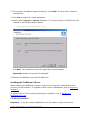
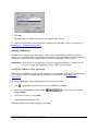
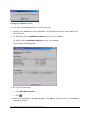
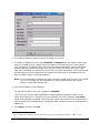
Deleting a User Profile
To delete a user profile, do the following:
1. From the File menu, choose Delete Profile.
The Delete Profile dialog box appears.
2. From the list, select the user profile to delete.
3. Click Delete.
4. When the confirmation message appears, click Yes.
5. If the profile has password protection, NetBeacon asks you for the password.
Type the password and then click OK.
6. Click OK to close the Delete Profile dialog box.
Setting Your Password
Passwords are used to secure your profile so that only authorized users have access to the
devices loaded in the profile through NetBeacon.
To set your password, do the following:
1. From the File menu, choose Save Profile As or New Profile.
2. Check the Requires Password Protection box.
NetBeacon Management Software ~ Installation and User's Guide
49
3. In the Profile Name text box, type the name of the new profile or choose one from the
drop-down list.
4. In the Profile Password field, type your password.
5. In the Profile Re-Enter Password field, type your password again.
6. Click OK.
Viewing NetBeacon License Information
To view information about the NetBeacon software license, choose License from the File
menu. The NetBeacon License dialog box displays the current license key code, the
expiration date (if you have a trial or demo version), and the name of the person to whom
the software is licensed.
Updating the NetBeacon License
The license key and the name of the licensee may be modified.
1. Click Update from the NetBeacon License dialog box shown above.
2. In the License key field, type your license key code.
3. Enter a name in the Licensed to textbox.
4. Click OK.
50
NetBeacon Management Software ~ Installation and User's Guide
Configuring the Database
Important:
This section is only applicable to the database version of NetBeacon.
With the database plugin installed, NetBeacon provides several options that determine how
and when data is logged on each device. To set up database management, do the following:
1. Under Windows: click the NetBeacon Server button on your taskbar.
Under UNIX: click the NetBeacon Server icon on your desktop.
The NetBeacon Server dialog box appears.
2. Click Database Options. In the Database Administration dialog box, the Devices list
displays the IP address or DNS name of each device configured for database
management. If this is the first time you are using NetBeacon, no devices are shown.
The status of the devices can be determined by the color of the text. Initially, all devices
are shown in blue. Green and red text only appears after a device is enabled to record
data.
Blue
The device has not been scheduled for discovery yet, is in the discovery process,
or has been disabled from logging data.
Green NetBeacon has discovered the device successfully and is recording data for this
device.
NetBeacon Management Software ~ Installation and User's Guide
51
Red
The device is enabled to log data, but NetBeacon failed to reach the device.
Additionally, if the device is enabled to log data, you will see *Recording* next to it.
Adding a Device for Database Management
You can add new devices to the database management list either individually or collectively.
To add a new device, one at a time, do the following:
1. From the Database Administration dialog box, click Add. The Add Devices dialog box
appears.
2. In the User-Specified Device text box, type the IP address or DNS name of the device
you want to add.
3. Click Add or hit ENTER to add the device to the list.
4. Repeat steps 2 and 3 until you have added all your devices.
5. Click OK.
Updating the Database Devices List
To add multiple devices from one or more NetBeacon client(s) for database management,
do the following:
1. From the Database Administration dialog box, click Add.
2. Click Update device list. The following message appears.
3. Click Yes. The NetBeacon server adds every active device being monitored by each of its
clients to the list.
52
NetBeacon Management Software ~ Installation and User's Guide
Important:
Only active devices are added to the list. Devices with an inactive or unknown
status are NOT included.
4. Click OK to add the list of devices to the database.
Removing Database Devices
To remove devices from the database management list, do the following:
1. Open the Database Administration dialog box.
2. Do one of the following:
•
Click the device to remove from the list.
•
To select more than one device, press the CTRL key and click each device you want to
remove.
•
To select a group of adjoining devices in the list, press the SHIFT key and click the
first and last devices in the group. Everything between the two devices will be
highlighted.
•
Click Select All if you want to delete all devices in the list.
3. Click Remove.
4. Click Yes when the confirmation message appears.
Logging Data
After you have specified the devices for database management, you can enable them to log
data.
1. To enable a device, select it from the list in the Database Administration dialog box.
Tip:
Click Select All if you want to enable all the devices in the list at once.
2. Click Enable.
3. Click Yes. Enabling a device starts its discovery process. You will see *Recording* next
to each device enabled for logging.
Tip:
In the NetBeacon Devices list, the disk icon
device is enabled for logging data.
NetBeacon Management Software ~ Installation and User's Guide
next to a device indicates that the
53
Creating Database Archives
NetBeacon maintains a database for each device enabled to log data. The database contains
information from the present to a maximum of 28 days. As new information is added to the
database, older data is dropped due to storage considerations. To preserve data that is
older than 28 days, NetBeacon provides a mechanism that produces database archives.
Database archives are data files that can easily be moved to a different location, read into
another database, or imported by other applications. These files also require significantly
less storage space than the database they represent.
To create database archives, do the following:
1. Select one or more devices from the list in the Database Administration dialog box.
2. Click Archive. The Archive Devices dialog box appears with the selected device(s)
highlighted. If multiple devices are selected, their archives will all contain data for the
same specified period of time.
3. Specify the time span for the database archives. The dates must be 28 days apart or
less. The start and stop dates use the format yyyy/mm/dd, where yyyy is the year, mm
is the month, and dd is the day.
To change the date, click on a number and do one of the following:
•
Type a new number.
•
Use the arrows at the right of the text box to increase or decrease the number.
4. Click Archive. The progress indicator displays the percentage of the process that has
been completed. When done, it reports Archive Progress:Completed.
5. For additional information about database archives, refer to Appendix B. Database
Archives.
54
NetBeacon Management Software ~ Installation and User's Guide
Chapter 4. Managing the Devices
This chapter describes the NetBeacon management features and how to use them to
monitor the devices on your network.
Important: You cannot change any folder information that is shaded (grayed); this
information is for display purposes only.
Displaying Device Information
The Device Information folder displays system information about the selected device,
including the device’s name, location, contact, description, and IP address.
The only information you can change is the device name, location and contact.
Tip:
Changes are displayed in blue until they are applied.
To view information about a device, do the following:
1. From the Devices list, select the device.
2. Click the Information tab to display the Device Information folder.
Do one of the following:
•
Click Apply to confirm any changes, then click OK.
•
Click Cancel to discard your changes.
•
Click Refresh to display the current information configured on the device.
•
Click Print to print the information contained in this folder.
NetBeacon Management Software ~ Installation and User's Guide
55
The following table lists the information shown in this folder, along with a brief description
of each field.
Name
Description
Device Name
Name of the device.
Device Location
Physical location of the device.
Device Contact
Person or group to contact regarding the device.
Description
A description of the device.
IP Address
The IP address of the device.
System Up Time
The length of time that the system has been running since it was last reset.
System Services
The system-level services available on the device.
System OS Version
The software version on the management card.
Configuring a Device
When you first configure a device, you identify its IP address, subnet mask, and default
gateway through a local console. Subsequent to this initial configuration, you can use
NetBeacon to change the configuration.
To configure a device, do the following:
1. From the Devices list, select the device to configure.
Important: The device must have an IP address and be accessible on the network
before it can be configured.
2. Click the Configuration tab.
The Configuration folder displays the Management Configuration parameters (top) and
the SNMP Configuration parameters (bottom).
56
NetBeacon Management Software ~ Installation and User's Guide
3. For devices with a dual Ethernet interface management card or that are in a stack, a
drop-down menu appears in the upper right corner of the Configuration folder. The
menu contains the IP addresses of every Ethernet port on all the management cards in
the chassis or stack. Select an IP address from the menu to display its management and
SNMP configuration.
4. To change the management configuration of a device, do the following:
•
In the IP Address text box, type the new IP address of the device.
NetBeacon removes the old IP address and adds the new one, while maintaining all
communications with the device.
•
In the Subnet Mask text box, type the subnet mask of the device.
•
In the Default Gateway text box, type the gateway of the device.
Setting the default gateway allows the device to send packets beyond its subnet.
Warning:
Setting an invalid IP address, mask, or gateway may cause you to lose
contact with the device.
Important: Initially, the IP address, subnet mask, and default gateway (optional) are
configured through the command line interface as described in the
Command Line Interface ~ Reference Guide.
The following table lists the Management Configuration information shown in this folder,
along with a brief description of each field.
Name
Description
IP Address
The Internet Protocol (IP) address uniquely identifying the device as a node on
the network.
Subnet Mask
A bit mask identifying which bits in the IP address correspond to the network and
subnet portions of the device IP address.
Default Gateway
The IP address of the router connecting to other networks on the device’s
network. The default gateway is necessary for the device to send packets to
nodes on subnets other than its own.
5. To tune the SNMP Configuration of NetBeacon, do the following:
•
In the SNMP Retry Count text box, type the number of times NetBeacon can retry
SNMP requests before deciding that the device is not reachable.
•
In the SNMP Timeout text box, type the number of seconds NetBeacon waits for a
response before reissuing a request.
•
In the READ Community text box, type a unique string to authorize read access to
the device.
NetBeacon Management Software ~ Installation and User's Guide
57
•
In the WRITE Community text box, type a unique string to authorize write access
to the device.
•
In the WRITE Community Confirm text box, retype the string to authorize write
access.
Important: Changing the READ or WRITE Community string can affect
communications between the management card and the device. If you
attempt to connect, NetBeacon prompts you for the correct community
string.
6. Do one of the following:
•
Click Apply to confirm any changes to the device configuration.
•
Click Cancel to discard your changes.
•
Click Refresh to display the current information configured on the device.
•
Click Reset System to reboot the device.
•
Click Print to print the information contained in this folder.
The following table lists the SNMP Configuration information shown in this folder, along with
a brief description of each field.
Name
Description
SNMP Retry Count
The number of times NetBeacon retries an SNMP request before
deciding the device is not available.
SNMP Timeout
The number of seconds NetBeacon waits for a response before
reissuing a request.
READ Community
A unique string authorizing SNMP read access to the device.
WRITE Community
A unique string authorizing SNMP write access to the device.
WRITE Community Confirm
A confirmation of the string entered in the WRITE Community field.
Monitoring the Chassis
The Stack folder displays information about all the chassis in the stack. For a device that is
not a stack, only a single chassis is listed in the folder.
58
NetBeacon Management Software ~ Installation and User's Guide
The following table lists the chassis information shown in this folder, along with a brief
description of each field.
Name
Description
Location
The location of the chassis.
Name
The name of the chassis.
Asset ID
User-defined asset tracking identifier.
Description
Details on the type of chassis.
Part Number
The part number assigned to the chassis for identification purposes.
Number of Slots
The number of slots the chassis contains.
Position
Position of the chassis in the stack. Position is “0” if the device is not part of a
stack.
Min Temp
The lowest temperature at which at the device can operate properly.
Max Temp
The highest temperature at which at the device can operate safely.
Temp
Current temperature of the device.
Displaying Chassis Information
To display chassis information, do the following:
1. From the Devices list, select the device.
2. Click the Stack tab.
3. From the Stack folder, select a chassis by double-clicking on it.
The Chassis Information dialog box appears. The top half of the dialog box displays
information relating to the chassis hardware.
To change the name and asset ID of the chassis, type them in the textboxes and click
Apply. Click OK when the confirmation message appears.
NetBeacon Management Software ~ Installation and User's Guide
59
Tip:
An alternate method to display the Chassis Information dialog box is to right-click
the chassis icon in the Devices list and select Show Dialog from the drop-down
menu.
4. Do one of the following:
•
Click Refresh to update the information shown for the chassis.
•
Click Reset Chassis.
•
Click Reset To Default to reset the chassis to its default settings.
The following table lists the Chassis Information shown in the top half of this dialog box,
along with a brief description of each field.
Name
Description
Name
The name of the chassis.
Asset ID
User-defined asset tracking identifier.
Description
Details on the type of chassis in which the modules are installed (for example,
number of slots and type).
Part Number
The part number assigned to the chassis for identification purposes.
Number of Slots
The number of slots the chassis contains: 2, 12 or 17.
Serial Number
The serial number assigned to the chassis for identification purposes.
Manufacture Date
The date the chassis was manufactured.
Revision Number
The version of the chassis backplane.
Displaying Temperature and Power Supply Information
The bottom half of the Chassis Information dialog box displays environmental information,
including the temperature of the chassis, the voltage supplied by each power supply, and
the operating status of each power supply. Voltage and temperature information are
displayed using both a graphical and textual format.
Tip:
60
Passing the cursor over the temperature gauge displays a tooltip that converts
the current temperature from degrees Celsius to Fahrenheit or vice versa.
NetBeacon Management Software ~ Installation and User's Guide
The following table describes the power supply information.
Name
Description
Supply #
A device may have one or two power supplies, denoted Unit A (on the left) and
Unit B (on the right).
Status
Operational status of the power supply, either ON or OFF.
Type
Type of power supply: AC or DC.
Minimum Volts
A predefined value representing the minimum voltage that the power supply should
provide.
Current Volts
The current voltage output by the power supply.
Maximum Volts
A predefined value representing the maximum voltage that the power supply
should provide.
Click the Temperature History or Voltage History button to view a graphical display of
the chassis’ temperature or power supply voltage over an extended period of time. (This
feature requires the device to be enabled for recording data, using the database version of
NetBeacon.)
Tip:
Double-clicking on a gauge also displays its associated history graph.
NetBeacon Management Software ~ Installation and User's Guide
61
To change the maximum time interval shown in the graph, choose one of the options from
the Time Span drop-down list.
Important: You may notice that the graph line does not begin at 0. Some time lag is
natural in NetBeacon graphs. When data is collected only once every 15
minutes, the latest data point may be as much as 15 minutes old. Make sure
the clocks on the client and server are synchronized and set to the correct
local time zone.
Receiving Traps
The Traps folder displays a message (SNMP Trap) whenever certain events occur in any of
the devices being monitored. NetBeacon provides numerous traps, including notification of
configuration and status changes or problems with a power supply, chassis, module, or port.
For example, a message can be sent if the power supply goes above or below the
acceptable voltage range or if the temperature of the chassis rises above the recommended
operating temperature.
Important: When recording events, NetBeacon uses the local PC time and not the time
from the device.
Monitoring Traps
To display trap alerts, click the Traps tab. The Trap Information folder displays each
message in a scrollable window.
The following table lists and describes the Trap Information fields shown in this folder.
Name
Flag
Description
indicates a new message which has not been acknowledged.
Alert
A brief description of the trap.
Device
The IP address of the device where the trap was generated.
Date/Time
The date and time when the event occurred.
62
NetBeacon Management Software ~ Installation and User's Guide
One or more messages may be acknowledged by selecting the message(s) and clicking
Acknowledge Traps. Acknowledging a message removes the blue NEW icon at the far left
of the table, but the message remains on the list. To acknowledge all new messages, click
Acknowledge All Traps.
Select one or more messages and click Clear Traps to delete them permanently from the
list. To remove all messages, click Clear All Traps.
Displaying the Trap Legend
NetBeacon has two categories of traps: Generic Traps and Enterprise Traps. Initially, all
available trap messages (except Generic EGP Neighbor Loss) are enabled. However, you can
disable individual messages to suit your network monitoring preferences.
To display the categories of traps along with a description of each one, do the following:
1. Click the Traps tab.
2. At the bottom of the Trap Information folder, click Trap Filter.
The following table lists all the traps and describes the conditions that trigger them when
enabled. Traps that are enabled are recorded in the Trap Log.
Name
Trap Event
Generic Cold Start
The management card is reset.
Generic Warm Start
The occurrence of a software error that caused a spontaneous reset.
Generic Link Down
A port loses link. (The port is not specified.)
Generic Link Up
A port detects link. (The port is not specified.)
Generic Authentication Failure
Invalid SNMP community string is used.
Generic EGP Neighbor Loss
Not Applicable.
NetBeacon Management Software ~ Installation and User's Guide
63
Name
Trap Event
Entity Configuration Change
A power supply or card is removed from or added to a chassis, or a
chassis is removed from or added to a stack.
Entity Insert
A power supply or card is installed in a chassis, or a chassis is added to
a stack.
Entity Remove
A power supply or card is removed from a chassis, or a chassis is
removed from a stack.
Entity Reset
A chassis or card is reset.
Power Supply Status Change
Power supply status changes from ON to OFF or vice versa.
Ethernet Port Link Status
Change
The presence of link on an Ethernet port is lost or detected.
SONET Port Link Status Change
The presence of link on a SONET port is lost or detected.
Sensor Threshold
The temperature or voltage exceeds the limits on a management card or
access line card; or the fiber optic power level is exceeded on an access
line card.
Redundant Switch Over
The active port changes from the primary to the secondary port on a
redundant interface line card.
Remote Fault Alarm
A remote access line card’s fiber port loses its receive link.
Ethernet Port Speed Change
The speed on an Ethernet port is changed.
TDM Port Link Status Change
The presence of link on a TDM port is lost or detected.
TDM Remote Fault Alarm
A remote TDM card’s fiber port loses its receive link.
Enet Port Far End Fault Alarm
A remote x133-xx card’s fiber port receiver fails to detect link.
Filtering Traps
1. From the Generic Traps or Enterprise Traps list, check or uncheck the boxes to include
or exclude specific messages.
2. Click Apply.
3. When the confirmation message appears, click OK.
3. Click OK to return to the Trap Information folder.
Tip:
64
When a dialog box offers both the OK and Apply buttons, click OK if you want
the dialog box closed after applying any changes. Click Apply if you want to
apply changes and keep the dialog box open.
NetBeacon Management Software ~ Installation and User's Guide
Managing Traps
Through NetBeacon, you can configure multiple management stations to monitor traps. If
you are using another SNMP software application, such as WebBeacon, all of its trap
managers are automatically added to NetBeacon’s list of trap managers, along with the
NetBeacon server. No trap managers are removed until you delete them.
Displaying the Trap Management Table
To view which hosts are configured to receive trap notices, do the following:
1. Click the Traps tab.
2. Click Trap Manager.
The Trap Manager table appears.
The following table lists the Trap Manager information shown above, along with a brief
description of each field.
Name
Description
IP Address
IP address of the workstation where trap notices are sent.
UDP Port
The User Datagram Protocol (UDP) port number.
Trap Manager Name
Name assigned to the trap manager.
Status
Indicates whether the manager is active or not in service. When active, traps
are sent to the manager. When not in service, traps are logged but not sent.
SNMP Version
The SNMP version, either V1 or V2C.
Adding a New Trap Manager
To add a new trap manager, do the following:
NetBeacon Management Software ~ Installation and User's Guide
65
1. Click the Traps tab.
2. Click Trap Manager.
3. Click Add.
The Add Trap Manager Destination dialog box appears.
4. In the IP Address text box, type the IP address of the destination server or device to
which traps will be sent.
5. In the UDP Port text box, type the trap manager’s UDP port number. The default number
is 9162. Port 162 is the standard SNMP trap port.
6. In the Name text box, type the name of the new trap manager.
7. Select V1 or V2C from the drop-down list to set the SNMP version that will be used to
send trap messages.
8. Select Active or Not In Service from the Status drop-down list. Traps are sent to the
manager if you select Active. Traps are recorded but not sent if you choose Not In
Service.
Important:
Make sure your trap management workstations are configured to receive
trap notices.
9. Click OK.
10. Click Apply or OK to update the trap destination table. Then click OK when the
confirmation message appears.
Reconfiguring a Trap Manager
After you have configured your trap managers, you can change the name, SNMP version
and status of a trap manager.
To edit trap management information, do the following:
1. Click the Traps tab.
66
NetBeacon Management Software ~ Installation and User's Guide
2. Click Trap Manager.
3. In the table, click the trap manager you want to modify.
4. Click Edit.
The following Edit Trap Manager Destination dialog box appears.
5. In the Name text box, type the new name of the trap manager.
6. Select V1 or V2C from the SNMP Version drop-down list.
7. Select Active or Not In Service from the Status drop-down list.
8. Click OK.
9. Click OK or Apply to update the trap destination table. Then click OK when the
confirmation message appears.
Deleting a Trap Manager
To remove one or more trap managers, do the following:
1. Click the Traps tab.
2. Click Trap Manager.
3. In the table, click the row of the trap manager you want to remove.
Tip:
To select more than one, press the CTRL key and select the other trap managers
you want to remove.
4. Click Delete.
5. Click OK or Apply.
6. When the confirmation message appears, click OK.
NetBeacon Management Software ~ Installation and User's Guide
67
Sending E-mail Notifications
In addition to viewing messages, you can customize NetBeacon to send automatic e-mail
notifications to one or more recipients when certain events occur.
Configuring E-mail Notifications
To enable e-mail notifications for the currently selected device/stack, do the following:
1. Click the Traps tab.
2. Click Trap E-mail Setup.
3. In the SMTP e-mail server text box, type the name of the host e-mail server.
4. To send e-mail notifications, all devices including the currently selected device must be
set to Enabled.
Tip:
To prevent the selected device from sending e-mail notifications, select Disabled
from the E-mail sending for current device drop-down list. All devices can be
stopped from sending messages by selecting Disabled from the E-mail sending
for all devices drop-down list.
5. From the Suppress repeated messages drop-down list, select No to allow all e-mails
messages to be sent to the recipient(s). To restrict a message to be sent no more than
once within a specified period, select the time interval from the list. For example, if you
choose 15 minutes, and the device records an Entity Reset trap twice within a 15minute period, only one e-mail message will be sent to the e-mail recipient(s).
6. Click Apply or OK.
7. When the confirmation message appears, click OK.
Next, you create a list of recipients that you want to notify. You can enable/disable specific
traps to individualize the list for each recipient.
8. To add a recipient to the notification list, click Add in the Trap E-mail Setup dialog box.
68
NetBeacon Management Software ~ Installation and User's Guide
The Trap E-Mail - Add Notice dialog box appears.
9. In the To text box, type the e-mail address of the recipient. To specify multiple
recipients, separate each recipient’s e-mail address with a semicolon (;).
10. In the From text box, type the e-mail address of the person sending the message.
11. In the Subject text box, type a description of the notice. This information is optional.
12. Click OK to add the recipient to the notification list.
13. Repeat Steps 8-12 to add additional recipients.
Each e-mail notification is saved temporarily in the E-mail trap notices for the current
device table. Its fields are described below.
Name
Description
To
E-mail address of the recipient of trap notices.
From
E-mail address of the sender of trap notices.
Subject
Description of the trap notice. (This field is optional and may be blank.)
Traps
Object identification numbers of the traps configured for the recipient.
NetBeacon Management Software ~ Installation and User's Guide
69
14. Click OK or Apply to keep any changes made to the Trap E-Mail Setup.
15. Click OK when the confirmation message appears.
Adding E-mail Notifications for Multiple Devices
NetBeacon only allows you to set up e-mail notices for one device or stack at a time. For
each additional device or stack you want to configure, do the following:
1. Close the Trap E-mail Setup dialog box for the currently selected device.
2. Choose a new device from the Devices list in the lower left section of the NetBeacon
window.
3. Repeat the steps in Configuring E-mail Notifications.
Editing an E-mail Notice
If you want to change any information for an existing e-mail notice recipient, do the
following:
1. In the table under the Trap E-mail Setup dialog box, click on the notice you want to
modify.
2. Click View/Edit.
3. Make the desired changes in the Trap E-mail - Edit Notice dialog box.
4. Click OK, then click Apply or OK.
5. Click OK when the confirmation message appears.
70
NetBeacon Management Software ~ Installation and User's Guide
Sending a Test E-mail Notice
To send a generic test message to verify e-mail notification by the NetBeacon, do the
following:
1. From the E-mail trap notices table, select the recipient of the test e-mail notice. You
may select more than one recipient.
2. Click Test.
3. Click OK when the verification message appears.
The recipient will receive the following test e-mail message.
Deleting an E-mail Notice Recipient
To delete a recipient from the e-mail trap notices list, do the following:
1. From the E-mail trap notices table, select the recipient to delete.
2. Click Remove.
3. Click Apply or OK, then click OK.
NetBeacon Management Software ~ Installation and User's Guide
71
Chapter 5. Configuring Modules and Ports
Through NetBeacon, you can monitor and configure all the modules1 and ports on your
device. In addition to overriding hardware switch settings, you can enable advanced
functions such as Switch On No Activity Received (SONAR) on the redundant interface line
card and Far End Fault on the T1/E1 card. You can also obtain complete Ethernet and RMON
port statistics on the access line cards.
Displaying Module Information
The Module Information folder displays information about the modules (e.g., the
management card and the access line card) installed in the selected device. If the device is
part of a stack, all modules in the entire stack are included.
Information includes the location, name, asset ID, type, and a brief description of the
module, along with its operating status, uptime, version, date of manufacture, and part
number.
1. Click the Modules tab to display the Module Information folder.
Tip:
Clicking a module in the chassis view also displays the Module Information folder.
The selected module is highlighted.
The following table lists the Module Information shown in this folder, along with a brief
description of each field.
1
Line cards are called modules in NetBeacon.
NetBeacon Management Software ~ Installation and User's Guide
73
Name
Description
Location
The chassis and slot where the module is installed.
Name
The user-assigned or default name for the module.
Description
Details on the module’s specifications.
Type
The type of module − a management card, an access line card, a single
interface line card, etc.
Up Time
The length of time the module has been in operation since startup. For version
1.3 or older modules, this field is not supported and will be displayed as
Unknown.
Oper Status
Operational status of the module, either Enabled (active) or Disabled
(inactive).
Asset ID
User-defined asset tracking identifier.
Version
The version number or letter of the module.
Manufacture Date
Date the module was manufactured.
Part Number
The part number assigned to the module for identification purposes.
2. To reset one or more modules, do the following:
•
Select one or more modules from the table by clicking on it. Hold down the CTRL key
while clicking to select multiple modules.
•
Click Reset Modules.
•
When the confirmation messages appear, click Yes, then click OK.
3. Click Refresh to display the current information configured for the modules.
4. To view information for a specific type of module, select it from the drop-down menu,
which displays all the types of modules installed in the chassis or stack.
In addition to the location, name, type, operating status, and number of ports, the
information shown for each module type includes functional settings that are unique to it.
The table below describes these settings.
74
NetBeacon Management Software ~ Installation and User's Guide
Name
Description
Auto Interface Line Card
Backpressure
Status of the backpressure function, which forces a collision on a port when it
cannot accommodate incoming data. See Configuring the 10/100Mbps Line
Card.
FD Flow Control
If FD Flow Control is enabled, the card will issue a PAUSE frame when there is
no buffer space available for incoming packets. See Configuring the
10/100Mbps Line Card.
Auto Recovery
Auto-Recovery allows the card to restart its fiber connection after a link loss
event. See Configuring the 10/100Mbps Line Card.
Single Interface Line Card, Access Line Card, Redundant Interface Line Card, Auto
Interface Line Card
LLCF (Link Loss
Carry Forward)
When LLCF is enabled, if one port loses link, the module will not transmit a
link pulse from the other port.
Single Interface Line Card
LLCF/CLCF (Copper
Loss Carry
Forward)
CLCF only applies to TX-FX gigabit cards. When CLCF is enabled, the fiber
port’s transmitter shuts down if the copper port stops receiving link pulses.2
Redundant Interface Line Card3
Mode Control
The mode control is either Dynamic Recovery or Select A/B.
Active Port
The active port is either Primary or Secondary.
Auto Restore
Primary Circuit
When enabled, the module reverts the active port back to the Primary port
when the primary link is reestablished.
Link Pulse Control
Link signals are sent out both the Primary and Secondary ports when Link
Pulse Control (LPC) is enabled. Link signals are sent out only on the active
port if LPC is disabled.
Redundant
Transmission
When enabled, transmits data on both the Primary and Secondary ports (LPC
must be enabled). When disabled, transmits data on the active port only.
2
See the Radiance Gigabit Single Interface Line Cards ~ Installation and User Guide, “Copper Loss Carry Forward
(CLCF),” for additional information.
3
See the Radiance 10Mbps or 100Mbps or 1000Mbps Redundant Interface Line Cards ~ Installation and User Guide
or the “redundant twister” Installation and User Guide, Step 2 “Set the DIP Switches,” for details regarding the
card’s switch settings.
NetBeacon Management Software ~ Installation and User's Guide
75
Name
Description
Secondary Switch
Occurred
Indicates whether or not the active port has changed.
Select A/B
Only applicable in Select A/B Mode. Select A enables the Primary port. Select
B enables the Secondary port.
SONAR
(Switch On No
Activity Received)
Not applicable to all redundant interface line cards. When enabled, the module
automatically changes its active port if the active port receives no data for at
least 2 seconds and data activity is detected on the backup port.
Changing a Module Name and Asset ID
1. Open the Module Configuration dialog box by doing one of the following:
•
From the table in the Modules folder, double-click the row containing the module to
rename.
•
Right-click the module in the chassis view and select Module Configuration from
the pop-up menu.
•
Double-click the image of the module’s thumbscrew in the chassis view.
The Module Configuration dialog box displays the current information relating to the
module you selected. The information displayed in the top half of the dialog box relates
to the module and the information displayed in the bottom half relates to the converters
on the module.
2. In the Name text box, type the name4 you want to assign to the module.
3. In the Asset ID text box, type the asset tracking identifier5 you want to assign to the
module.
4. Click Apply, then click OK.
4
There is a limit of 32 characters for the module name. Do not use the following characters: . ; & = : " < > .
5
There is a limit of 32 characters for the asset ID. Do not use the following characters: . ; & = : " < > .
76
NetBeacon Management Software ~ Installation and User's Guide
The following table describes the fields shown in the top half of the Selected Module
Information section of the Module Configuration dialog box.
Name
Description
Name
Default or user-defined name of the module.
Type
The type of module installed in the slot − a management card, an auto interface
line card, a gigabit interface line card, an OC-3 interface line card, an OC-12
interface line card, an access line card, a single interface line card, a TDM card,
or a redundant interface line card.
Description
Details on the module’s specifications.
Part Number
The part number assigned to the module for identification purposes.
Serial Number
The serial number assigned to the module for identification purposes.
Manufacture Date
The date the module was manufactured.
Hardware
Revision Number
The version number of the module.
Diagnostic Test
Status
The results of the diagnostics test of the module.
Oper Status
Operational status of the module, either Enabled or Disabled.
Asset ID
User-defined asset tracking identifier.
The bottom half of the dialog box provides information relating to the module’s media
converter(s). Refer to Displaying Converter Information for details about these fields.
NetBeacon Management Software ~ Installation and User's Guide
77
Displaying Management Module Information
The management card is located in slot 12 of a 12-slot chassis, slot 17 of a 17-slot chassis,
or either slot of a two-slot chassis.
To display management card details, do the following:
1. Double-click the management card row from the Module Information folder.
Tip:
Double-clicking the management module in the chassis view also displays this
dialog box.
The bottom half of the dialog box provides detailed information about the management
card’s Ethernet port(s).
2. Click the Advanced button.
The Management Module Details dialog box appears.
78
NetBeacon Management Software ~ Installation and User's Guide
Name
Description
Image Information
Image
Software image type.
Name
File name of the software image.
Version
Version number of the software image.
Memory Information
RAM Memory Size
The amount of volatile RAM memory on the card.
Flash Memory Size
The amount of non-volatile flash memory on the card.
NVRAM Memory Size
The amount of non-volatile memory on the card. This memory is backed
up by battery.
Embedded Servers
Telnet Server
Enable or disable the Telnet server.
FTP Server
Enable or disable the FTP server.
HTTP Server
Enable or disable the Web server.
HTTP Redirect
Set the Web server so it points to the local device (Local) or redirect it to
another IP address or URL (Redirected).
HTTP Redirection URL
The IP address or URL where the Web server will go to if the Web server is
redirected away from the local device.
BootP Server
Enable or disable the BootP server. This field is only applicable to the
R502-M management module.
Displaying a Remote Access Line Card or Access ONU Information
A remote access line card or access optical network unit (ONU) appears below the card it is
connected to in the chassis view, if Show Remotes is enabled in the View menu. To see a
larger image of the remote card or ONU, double-click on the image of the remote card/ONU.
The module information and a larger view of the line card or ONU appear in the dialog box.
NetBeacon Management Software ~ Installation and User's Guide
79
In addition to the standard information provided in the Selected Module Information section,
two additions fields are shown for an access product.
Name
Description
PIC Revision
Primary Interexchange Carrier revision number
FPGA Revision
Field-Programmable Gate Array revision number
Configuring a Converter
The bottom half of the Module Configuration dialog box contains information regarding the
media converters on the selected module.
The information includes the location of the converter, its name, operational status, number
of ports, type, and whether the Link Loss Carry Forward (LLCF) or Copper Loss Carry
Forward (CLCF) function is enabled, disabled or not applicable.
The following table lists the converter information, along with a brief description of each
field.
80
NetBeacon Management Software ~ Installation and User's Guide
Name
Description
Location
The chassis number in the stack, and the slot or converter number in the
chassis.
Name
The user-assigned or default name of the converter.
Oper Status
Operational status of the media converter, either Enabled (active) or Disabled
(inactive).
Ports
The number of ports on the converter.
Type
The type of media converter (e.g., an access line card, a single interface line
card, or a TDM T3 card).
LLCF/CLCF
When LLCF is enabled, if one port loses its link, the converter will not transmit
a link pulse from the other port.
CLCF is only applicable to the 1000Mbps TX-FX line cards. When CLCF is
enabled, the fiber port’s transmitter shuts down if the copper port stops
receiving link pulses.
Displaying Converter Information
Another way to view converter information is to open the Converter Configuration dialog
box using one of the following methods:
•
From the Module Configuration dialog box shown above, double-click the row
containing the converter.
•
Double-click the module in the chassis view.
•
Right-click the module in the chassis view and select Converter Configuration from
the pop-up menu.
The Converter Configuration dialog box displays the current information relating to the
converter you selected. The information displayed in the top half of the dialog box relates to
the converter.
The bottom half of the dialog box displays detailed information about each of the ports on
the converter. Refer to Displaying Port Details for descriptions of the Port fields shown.
Assigning a Converter Name
1. Open the Converter Configuration dialog box using one of methods described in
Displaying Converter Information.
2. In the Name text box, type the name you want to assign to the converter.
NetBeacon Management Software ~ Installation and User's Guide
81
3. Click Apply, then click OK.
Applying Link Loss Carry Forward
In addition to changing the name, you can enable or disable Link Loss Carry Forward (LLCF)
on the modules that have this function.
When LLCF is enabled, if one port loses its link, the converter will not transmit a link pulse
from the other port.
1. Open the Converter Configuration dialog box using one of methods described in
Displaying Converter Information.
2. From the Link Loss Carry Forward drop-down list, select Enabled or Disabled.
3. Click Apply, then click OK.
82
NetBeacon Management Software ~ Installation and User's Guide
Applying Copper Loss Carry Forward
Copper Loss Carry Forward (CLCF) is only applicable to the 1000Mbps TX-FX line cards.
CLCF is disabled by default.
When CLCF is enabled, the fiber port’s transmitter shuts down if the copper port stops
receiving link pulses. To apply CLCF, do the following:
1. Open the Converter Configuration dialog box for the line card to configure.
2. From the Copper Loss Carry Forward drop-down list, select Enabled.
3. Click Apply, then click OK.
Configuring the Redundant Interface Line Card
To configure a redundant interface line card, do the following:
1. In the chassis view, double-click the module to configure.
The Converter Configuration dialog box for a redundant line card appears.
2. Click Advanced.
The Redundant Interface Line Card Details dialog box displays the Mode and Mode
Control settings for the selected module and active port. You can override the DIP
switches on the board by changing these settings.
3. Select the Mode option: Dynamic Recovery Mode (DRM) or Select A/B.
NetBeacon Management Software ~ Installation and User's Guide
83
Dynamic Recovery Mode
When Dynamic Recovery Mode is active, both links are directed to the same network.
Only the primary link is active unless a failure occurs, in which case the secondary link
assumes primary control, or redundant transmission mode is enabled.
If you select the auto restore option, then the primary link is reactivated as soon as it is
restored. Otherwise, the secondary port remains active if its link does not fail.
Use DRM when you want to ensure continuous network connectivity and secure
uninterrupted user access in the event of a link failure.
Dynamic
Recovery
Mode:
Auto Restore Primary Circuit:
• Enable – reverts the active port back to the primary port when the
primary link is reestablished.
• Disable – keeps the secondary port as the active port even if the
primary link is reestablished.
Link Pulse Control (LPC):
• Enable – sends an idle signal on both the primary and secondary
ports.
• Disable - sends an idle signal on only the active port.
Redundant Transmission:
• Enable – sends data on both the primary and secondary ports
simultaneously.
• Disable – sends data on the active port only.
Tip:
You must enable LPC to enable redundant transmission mode.
Applying SONAR
For redundant interface line cards with Switch On No Activity Received (SONAR), an
additional parameter appears in the top half of the Redundant Interface Line Card Details
dialog box. SONAR affects the module’s response to a loss of activity (LOA) for two seconds
on the active port. SONAR is applicable only in Dynamic Recovery Mode with Link Pulse
Control enabled.
84
NetBeacon Management Software ~ Installation and User's Guide
The other switch settings do not affect SONAR operation. However, SONAR will override the
Auto Restore Primary Circuit switch. If both these switches are enabled, the active port will
not automatically revert back to the primary port (after switching to the secondary port) if
the primary port has link but no data activity. Data activity on the primary port must also be
detected during the two-second time-out period before the active port reverts back to the
primary port.
To enable SONAR, do the following:
1. In the Redundant Interface Line Card Details dialog box, choose Enabled from the
SONAR drop-down list.
2. Set the Mode to Dynamic Recovery Mode.
3. Make sure that Link Pulse Control is Enabled.
4. For a Gigabit redundant card, the loss of activity (LOA) period can be set anywhere from
1 to 31 seconds. Slide the pointer to select the desired number of seconds. If the active
port remains idle for the specified time, the redundant interface will verify activity on the
secondary port, and switch to that port once traffic is detected.
5. Click Apply.
6. A message appears stating that the operation was successful. Click OK.
Select A/B Mode
When Select A/B is active, each link on the redundant interface line card operates
independently and is directed to a different network. Only one link (primary or secondary) is
active at a time.
NetBeacon Management Software ~ Installation and User's Guide
85
Use this mode to redirect traffic from one network to another, in less critical points in the
network where full redundancy is not required.
Select A/B: Select A – Enables the primary port.
Select B – Enables the secondary port.
Do one of the following:
•
Click Apply to confirm your changes.
•
Click Cancel to discard your changes and return to the Converter Configuration
dialog box.
•
Click OK to return to the Converter Configuration dialog box.
Configuring the 10/100Mbps Line Card
The 10/100Mbps Auto Interface Line Card (AutoTwister) is a rate adapter that connects
10Mbps devices to 100Mbps devices, copper-based networks to fiber-based networks, and
full-duplex systems to half-duplex systems. Depending on your model, various features are
available for this card.
To configure a 10/100Mbps line card, do the following:
•
In the chassis view, right-click the module to configure and select Converter
Configuration from the pop-up menu.
The Converter Configuration dialog box for a 10/100Mbps line card appears.
Link Loss Carry Forward and Full-Duplex Flow Control
1. For a 10/100Mbps line card with LLCF functionality, you can select Enabled or Disabled
from the drop-down list, and then click Apply. The default is LLCF disabled.
86
NetBeacon Management Software ~ Installation and User's Guide
2. On some models, an additional feature called Full-Duplex (FD) Flow Control is provided.
If you enable FD Flow Control, the 10/100Mbps line card will issue a PAUSE frame when
there is no buffer space available for incoming packets. Select Enabled or Disabled
from the drop-down list, and then click Apply. This setting is enabled by default.
Backpressure (Half-Duplex Flow Control)
1. At the bottom of the Converter Configuration dialog box, click Advanced.
The Backpressure dialog box appears. Here you can change the card’s backpressure
setting. The default setting is disabled.
Backpressure can be enabled only on ports operating at half duplex. When backpressure
is activated, the 10/100Mbps card generates a jamming pattern to force a collision on a
port when the converter cannot allocate a buffer for the port’s incoming packets.
Activating backpressure enables it on both ports of the card. Backpressure is ignored in
full duplex because collisions are not generated in this mode.
2. Select Disabled or Enabled.
3. Do one of the following:
•
Click Apply and then OK to confirm your change.
•
Click Cancel to discard your change and return to the Converter Configuration dialog
box.
•
Click OK and then OK to confirm any changes and return to the Converter
Configuration dialog box.
Auto-Recovery
The x643-xx 10/100Mbps line cards include the Auto-Recovery feature to assist in
troubleshooting remote connections. Auto-Recovery allows the card to restart its fiber
connection after a link loss event.
Auto-Recovery is enabled only when all of the following conditions are met:
•
Auto-Recovery is enabled.
NetBeacon Management Software ~ Installation and User's Guide
87
•
Link Loss Carry Forward is enabled.
•
Link Loss Return is enabled.
•
Auto-Negotiation is disabled.
Through NetBeacon, you can easily configure the settings to automatically enable AutoRecovery by doing the following:
1. In the Converter Configuration dialog box, click Related Settings. (If all the conditions
necessary for Auto-Recovery are already set correctly, this button will be dimmed.)
The Engaging the Auto-Recovery Circuit dialog box appears. It lists the current status of
the four settings upon which Auto-Recovery depends.
2. Click Change all settings needed to engage Auto-Recovery to make all the required
changes in one simple step.
3. Click OK. When you return to the Converter Configuration dialog box, the Related
Settings is now unavailable.
Managing the Chassis Stacking Line Card
The Chassis Stacking Line Card is a 10/100Mbps four-port TX switch that can be used to
stack up to four Metrobility chassis. The Module Configuration dialog box for the card
provides the standard module information, with one addition—the Complex Programmable
Logic Device (CPLD) revision number.
To configure a chassis stacking line card, do the following:
•
In the chassis view, right-click the module to configure and select Converter
Configuration from the pop-up menu.
The Converter Configuration dialog box for a chassis stacking line card appears.
There are three settings you can modify through this window.
88
NetBeacon Management Software ~ Installation and User's Guide
Port Duplex, and Full and Half Duplex Flow Control
3. The Port Duplex setting determines the duplex mode on all ports that have autonegotiation disabled. The ports will operate at full duplex if Port Duplex is enabled. The
ports will operate at half duplex if the setting is disabled. Select Enabled or Disabled
form the drop-down list.
If auto-negotiation is enabled on a port, that port will ignore the Port Duplex switch
setting. The duplex mode will be determined through the auto-negotiation process.
4. Full-Duplex (FD) Flow Control is provided as a means of avoiding packet loss during
times of network congestion. This setting can only be changed through software control
and is enabled by default. With FD Flow Control enabled, the chassis stacking line card
will issue a PAUSE frame if there is no buffer space available for incoming packets.
Select Enabled or Disabled from the drop-down list.
4. A
Backpressure can be enabled only on ports operating at half duplex. When backpressure
is activated, the 10/100Mbps card generates a jamming pattern to force a collision on a
port when the converter cannot allocate a buffer for the port’s incoming packets.
Activating backpressure enables it on both ports of the card. Backpressure is ignored in
full duplex because collisions are not generated in this mode.
5. Select Disabled or Enabled.
6. Do one of the following:
•
Click Apply and then OK to confirm your change.
•
Click Cancel to discard your change and return to the Converter Configuration dialog
box.
•
Click OK and then OK to confirm any changes and return to the Converter
Configuration dialog box.
NetBeacon Management Software ~ Installation and User's Guide
89
Displaying Access Line Card Details
The access line card contains three internal voltage regulators and a temperature sensor.
To view information about the card’s regulators and sensor, do the following:
From the Module Information folder, double-click the row containing an access line card.
The Module Configuration dialog box appears.
1. Click Advanced.
The table below describes the color coding used on the gauges.
Color
Description
Green
Normal operating range.
Yellow
Warning: above or below the recommended operating range.
Blue
Danger: voltage/temperature is too low.
Red
Danger: voltage/temperature is too high.
2. Click Temperature History or Voltage History to view a graphical display of either
the card’s temperature or regulated voltages over an extended period of time. (This
feature requires the database plugin on your NetBeacon server.)
Tip:
90
Double-clicking on any of the gauges also displays the graphs.
NetBeacon Management Software ~ Installation and User's Guide
3. To change the maximum length of time shown in the graph, select one of the options
from the Time Span drop-down menu.
Applying Write-Protection
By default, the access line cards are not write-protected. To prevent a remote access line
card from making changes to the locally managed card, do the following:
1. Select Read Only from the Remote Write Protect drop-down list in the Access Line Card
Module Details dialog box.
2. Click Apply, then click OK.
Configuring the Ports
The Ports folder displays information about the ports on the selected device. If the device is
part of a stack, the ports on the other chassis in that stack are also displayed. In addition to
the port information, the Ports folder provides an option to display the Ethernet interface
statistics on the management card(s). If the chassis or stack includes an access line card,
an option to view RMON statistics appears. If a T1/E1 card is installed, an option to view
TDM information appears.
Displaying Port Details
Click the Ports tab to display the Port Information folder. Make sure Port Information is
selected from the drop-down menu. The information in this table is for display purposes
only and cannot be changed.
NetBeacon Management Software ~ Installation and User's Guide
91
Tip:
Clicking a port in the chassis view also opens the Ports folder. (The port you clicked
is highlighted.)
The following table lists the information shown in the Ports folder, along with a brief
description of each field.
Name
Description
Location
Chassis number in the stack, slot in the chassis, and port on the card. For a
remote access line card, the remote card and port numbers are also included.
Name
Name assigned to the port.
Type
The port’s media type.
Speed
Speed in megabits per second (Mbps).
Oper Status
Operational status of the port, either Enabled or Disabled.
Duplex
Duplex mode of the port, (Full, Half, or N/A).
Auto Negotiation
Auto-negotiation status on the port (Enabled, Disabled, or N/A).
Link Status
Indicates whether or not link is detected.
Link Loss Return
Link Loss Return status on the port (Enabled, Disabled, or N/A).
Cross Over
Indicates whether a copper port’s MDI-X/MDI-II switch is set to Parallel or
Crossed Over. Not applicable to fiber ports.
Displaying Management Module Statistics
To view the Ethernet port statistics for the management cards installed in each chassis of
the selected stack, do the following:
1. Select Interface Statistics from the drop-down menu in the Ports folder.
92
NetBeacon Management Software ~ Installation and User's Guide
The following table lists and describes the Interface Statistics fields.
Name
Description
Location
The chassis, slot and port numbers of the management card.
IfIndex
The interface index number.
In Octets
Number of bytes received.
Out Octets
Number of bytes transmitted.
In Errors
Number of inbound packets with errors.
Out Errors
Number of outbound packets with errors.
In Discards
Number of inbound packets discarded with no errors.
Out Discards
Number of outbound packets discarded with no errors.
2. Click Clear Counters to reset all the counters to 0.
3. Click Show Deltas to display the difference between the totals shown on the screen and
the totals when you click the button.
4. Click Refresh to update the statistics.
5. Click Print to obtain a printout of the Interface Statistics table.
Displaying RMON Statistics
To view the complete Remote Monitoring (RMON) Group I Ethernet Statistics for the access
line cards, select RMON+ Statistics from the drop-down menu in the Ports folder. Scroll to
the right to view all the information.
NetBeacon Management Software ~ Installation and User's Guide
93
Viewing TDM Information
If you have any TDM cards installed in your chassis/stack, select TDM Information from
the Ports folder drop-down menu. Scroll to the right to view all the information.
Changing the Port Name
You can view additional port information from the Ports Configuration dialog box. For cards
such as the redundant interface line card, the only information you can change is the port
name.
1. Open the Port Configuration dialog box by doing one of the following:
•
From the Ports tab, select a port by double-clicking it.
•
Double-click the port in the chassis view.
The Port Configuration dialog box appears.
94
NetBeacon Management Software ~ Installation and User's Guide
2. In the Name text box, type the name6 to assign to the port.
3. Click Apply.
4. When the confirmation message appears, click OK.
5. Click OK to return to the Ports folder.
Applying Link Loss Return
In addition to the name, you can enable or disable Link Loss Return7 (LLR) on any fiber port
with this feature. LLR works in conjunction with Link Loss Carry Forward (LLCF). When a lost
link signal is returned to an unmanaged card, that lost link must then be carried forward to
a managed device for trap generation.
When LLR is enabled, the port’s transmitter shuts down if its receiver fails to detect a valid
receive link. LLR should only be enabled on one end of a link and is typically enabled on the
unmanaged or remote device.
To apply LLR, do the following:
1. In either the chassis view or the Ports folder, double-click the port to configure.
6
There is a limit of 32 characters for the port name. Do not use the following characters: . ; & = : " < > .
7
For additional information, refer to “Link Loss Return” in the user guide for the card you are configuring.
NetBeacon Management Software ~ Installation and User's Guide
95
2. Choose Enabled from the Link Loss Return drop-down list.
3. Click Apply. When the message appears, click OK.
Configuring the 10/100Mbps Ports
Depending on the type of 10/100Mbps auto interface line card (AutoTwister) installed, there
are two or three port settings that can be configured through NetBeacon. These include
auto-negotiation, duplex, speed, and Link Loss Return. The duplex mode can be changed on
any 10/100Mbps port. For a copper port, speed and auto-negotiation can also be changed.
For a fiber port, Link Loss Return can be enabled or disabled.
To configure the 10/100Mbps ports, do the following:
1. Double-click the port to configure in either the chassis view or the Ports folder.
2. The Port Configuration dialog box appears. The dialog box for a copper port is shown on
the left. The dialog box for a fiber port is shown on the right.
Select the port settings from the drop-down lists.
For a copper port, do any of the following:
•
Set Speed to 10Mbps or 100Mbps.
•
Set Duplex Mode to Half or Full.
•
Set Auto-Negotiation to Disabled or Enabled.
For a fiber port, do any of the following:
•
Set Duplex Mode to Half or Full.
•
Set Link Loss Return to Disabled or Enabled.
Changing these settings will override the DIP switches8 on the 10/100Mbps line card.
8
Refer to the Intelligent 7500 10/100 AutoTwister Module Installation and User Guide or the Radiance 10/100Mbps
Interface Line Cards Installation and User Guide, Step 2 “Set the Switches,” for additional information.
96
NetBeacon Management Software ~ Installation and User's Guide
3. Click Apply, and then click OK.
Configuring the R133 Ports
The 100Mbps TX-FX R133 ports include additional functions that are not available on other
single interface line cards. These functions include Far End Fault notification, autonegotiation, duplex selection, and remote loopback testing.
To configure the R133 ports, do the following:
1. Double-click the port to configure in either the chassis view or the Ports folder.
2. The Port Configuration dialog box appears. The dialog box for a copper port is shown on
the left. The dialog box for a fiber port is on the right.
Select the port settings from the drop-down lists.
For a copper port, do any of the following:
•
Set Duplex Mode to Half or Full.
•
Set Auto-Negotiation to Disabled or Enabled.
If auto-negotiation is disabled, the duplex setting will determine the mode at
which the port operates. When auto-negotiation is enabled, the copper port will
advertise full duplex capability if the duplex mode is set to full. The copper port
will advertise half duplex capability if the duplex mode is set to half.
For a fiber port, do any of the following:
•
Set Remote Loopback to Disabled or Enabled. During remote loopback, the
R133 card generates a test pattern that is sent to the remote unit, which then
returns the test pattern back to the R133 card. The card reads the returned data
and verifies proper transmission. To run the remote fiber loopback test, set
Remote Loopback to Enabled and make sure the Loopback Response setting on
the remote unit is also enabled. (If the remote unit is a 100Mbps Delta Class
“twister”, be sure that its DSLB DIP switch is OFF.)
NetBeacon Management Software ~ Installation and User's Guide
97
•
Set Loopback Response to Disabled or Enabled. This setting determines the
response of the fiber port to requests to enter remote loopback. If the setting is
disabled, the port will ignore all remote loopback requests. If the setting is
enabled, the port will permit remote loopback to occur. That is, it will return the
test data back to the sending device.
•
Set Far End Fault (FEF) to Disabled or Enabled. When FEF is enabled, the loss
of inbound link pulses on the port generates an alarm which is sent out the port’s
transmitter. FEF also enables the port the read the FEF alarm. To function
properly, the FEF setting must be the same on both the local and remote x133
line cards.
Changing these settings will override the DIP switches9 on the x133 line card.
3. Click Apply, and then click OK.
Configuring the Access Line Card Ports
Through NetBeacon, you can override the hardware switches on the access line card and
modify its internal default settings. You also can view its RMON port statistics and data
history as graphs.
To change the settings on an access line card, do the following:
1. Double-click the port to configure in either the chassis view or the Ports folder.
The Port Configuration dialog box for a fiber port (left) or a copper port (right) appears.
9
Refer to the Radiance 100Mbps Single Interface Line Cards Installation and User Guide, Step 2 “Set the
Switches,” for additional information.
98
NetBeacon Management Software ~ Installation and User's Guide
2. For a fiber port, you can configure the following settings: Administrative Status, Link
Loss Return, Loopback, and Far End Fault. For a copper port, you can configure AutoNegotiation, Administrative Status, and Loopback (locally managed card only).10
To change any these port settings, select Enabled or Disabled from the drop-down list,
and then click Apply. Click OK when the confirmation message appears.
Name
Description
Admin Status
When enabled, the port sends and receives data, including management
packets. When disabled, data is neither sent to nor received from the port.
However, the port continues to accept, process, and transmit management
packets.
Auto-Negotiation
When enabled, the copper port advertises full/half duplex capability. Speed
is not auto-negotiated and set to 100Mbps. When disabled, the copper port
is set to full duplex.
Far End Fault
(FEF)
When FEF is enabled on a remote line card and it loses its receive fiber link,
the card sends an unsolicited alarm to the locally managed card. When
disabled, the remote card does not send an alarm if it loses its receive fiber
link.
Link Loss Return
(LLR)
When LLR is enabled, loss of the port’s receive link disables its transmit link.
When disabled, the port continually transmits an idle signal.
Loopback
When disabled, the port sends data to the receiver. When enabled, the port
returns its incoming data back to the sender, while continuing to receive and
send management packets. Management packets are not looped back to the
sender. Loopback can only be applied to one port at a time because
enabling loopback on one port disables the opposite port. Not applicable to
the remote copper port.
3. For a singlemode fiber optic port, the input and output laser power levels11 are displayed
in the port configuration dialog box. Click the Receive Level History or Transmit
Level History button or double-click on either of the gauges to view a history of the
data over a period of time. (This feature requires the database plugin on your NetBeacon
server.)
10
Refer to the Radiance Access Line Cards ~ Installation and User Guide, “Software Settings,” for additional
information.
11
Refer to the Radiance Access Line Cards ~ Installation and User Guide, “Singlemode Fiber Optic Power Monitors,”
for additional information.
NetBeacon Management Software ~ Installation and User's Guide
99
4. To change the maximum time interval shown in the graph, select one of the options
from the Time Span drop-down list.
5. Click Close to return to the Port Configuration dialog box.
Displaying Port Statistics
To view the port’s RMON statistics, click the Statistics tab on the Port Configuration dialog
box. The current totals and the deltas are displayed. Deltas are the difference between the
current totals and the totals from the previous sampling. The time between samplings
typically ranges between 15 and 60 seconds.
100 NetBeacon Management Software ~ Installation and User's Guide
Viewing Data History Graphs
1. To view pie charts showing the various packet types received, the sizes of those
packets, and the types of error packets received, click the Graphs tab.
2. Click one of the three History buttons or double-click on any of the pie charts to view a
graph displaying those statistics over a period of time.
3. Use the drop-down menu at the bottom of the dialog box to change the time span
shown in the graph. For the Packet Size History graph, only the two-hour option is
available.
Important: Without the database plugin, the maximum time interval shown in the graphs
is two hours.
NetBeacon Management Software ~ Installation and User's Guide
101
Provisioning Bandwidth
1. To configure the bandwidth settings for the access line card, select the copper port and
click the Bandwidth tab. (This tab cannot be selected for a fiber port.)
The top half displays information relating to the incoming bandwidth, and the bottom
half displays information relating to the outgoing bandwidth.
The yellow arrowheads point to the highest levels attained in each gauge. Click Reset
Peak Level to reset the pointer.
Note that the gauges do NOT use the same units. The bandwidth gauges on the left
display data in megabits per second (Mbps), while the blocked packet gauges on the
right display the percentage of the total packets which were blocked and then dropped.
Click the Statistics tab to see further details about the information shown in the
gauges.
2. To configure the bandwidth settings, do the following:
•
Set the maximum burst size by selecting one of the following options from the
Receive or Transmit Burst Length drop-down list:
16, 32,64,128, or 256 KB.
This determines the maximum data burst size permitted in that direction. The
access line card provides full access to the channel bandwidth until the burst
threshold is reached.
•
Set the receive or transmit bandwidth by typing a number between 1 and 100.
This sets the maximum amount of data that can be carried over the network in
megabits per second (Mbps).
•
Click Apply, and then click OK.
102 NetBeacon Management Software ~ Installation and User's Guide
3. Click History or double-click on any of the gauges to view a graph displaying the
receive or transmit bandwidth usage over a specified period of time.
4. To change the maximum time interval shown, select one of the options from the Time
Span drop-down menu. Intervals greater than two hours require the database plugin.
Configuring the T1/E1 Ports
To configure a port on the T1/E1 card, do the following:
1. Double-click the port to configure in either the chassis view or the Ports folder.
2. The Port Configuration dialog box appears. The dialog boxes for a T1 copper port (left)
and a T1 fiber port (right) are shown below.
3. In the Name textbox, type the name12 to assign to the port.
4. To enable or disable the port, select Enabled or Disabled from the Admin Status dropdown list. Disabling a port has no effect on the incoming data, however, outgoing data
from the port will be dropped and AIS will be sent.
5. Set Local Loopback according to the following:
For normal operation, set Local Loopback to Disabled.
12
There is a limit of 32 characters for the port name. Do not use the following characters: . ; & = : " < > .
NetBeacon Management Software ~ Installation and User's Guide
103
If you want the inbound data on the copper or fiber line to be regenerated and sent back
to the sending device, set Local Loopback to Enabled. Local loopback can also be
enabled on both ports at the same time.
6. Click Apply, and then click OK.
Selecting the Line Code and Line Buildout
1. To set the line code or line buildout on a T1/E1 line card, double-click on its copper port.
2. From the TX Line Code drop-down list, select B8ZS or AMI for a T1 card, or select
HDB3 or AMI for an E1 card.
3. To set the line buildout for a T1 card, select one of the options from the Line Buildout
drop-down menu. The line buildout determines the shape of the transmitter’s output
pulse. Line buildout is not applicable to E1 cards.
4. Click Apply, and then click OK.
Setting BERT 511, Remote Loopback, and Far End Fault
1. To configure BERT 511, remote loopback, or Far End Fault (FEF) for the T1/E1 line card,
double-click on its fiber port.
2. Set BERT to Enabled if you want the fiber transmitter to send a test sequence on the
data channel to the remote unit. The remote unit can be either another line card or a
standalone. Set BERT to Disabled for normal operation.
Important:
To test the fiber connection between two T1/E1 line cards, both BERT and
Remote Loopback must be enabled individually. The two functions are set
automatically through the DIP switch, BR.
3. Set Remote Loopback to Enabled to force the data on the fiber line to loop back at the
remote end. Only the data bits will be looped, not the management bits. Set Remote
Loopback to Disabled for normal operation.
4. Set Far End Fault to Enabled to send an unsolicited alarm via the fiber management
channel if it loses its carrier or receives AIS. Set Far End Fault to Disabled if you don’t
want the remote card to receive an alarm. Far End Fault is enabled by default.
5. Click Apply, and then click OK.
Configuring the T3/E3 Ports
To configure a port on the T3/E3 card, do the following:
1. Double-click the port to configure in either the chassis view or the Ports folder.
The Port Configuration dialog box appears. The dialog box for a T3 copper port is shown
below.
104 NetBeacon Management Software ~ Installation and User's Guide
2. In the Name textbox, type the name13 to assign to the port.
3. To enable or disable the port, select Enabled or Disabled from the Admin Status dropdown list. Disabling a port stops the flow of data to and from that port. If the copper
port is disabled, no signals will be sent from the coaxial transmitter, and an unframed
all-ones pattern will be transmitted over the fiber line to the remote line card. If the
fiber port is disabled, no signals will be sent from the fiber transmitter, and an unframed
all-ones pattern will be passed from the copper port. Once a port is disabled, the only
way to enable it again is through software.
Note: An all-ones pattern indicates an alarm indication signal (AIS) for the E3 line cards
only. For T3 cards, the all-ones pattern is simply transmitted to the remote
device; it does NOT indicate AIS.
4. Set Local Loopback to the following:
For normal operation, set Local Loopback to Disabled.
The T3/E3 line card provides independent copper and fiber loopback modes. To set
either the copper port or the fiber port into loopback, set Local Loopback to Enabled.
When local loopback is enabled, incoming data is both transmitted to the remote device
and returned to the sending device. Copper and fiber loopback cannot be enabled at the
same time.
5. Click Apply, and then click OK.
13
There is a limit of 32 characters for the port name. Do not use the following characters: . ; & = : " < > .
NetBeacon Management Software ~ Installation and User's Guide
105
Setting the T3 Line Buildout
1. For a T3 line card, an additional option is provided to set the line buildout on the copper
port. Line Buildout is not applicable to E3 cards. Double-click on the copper port.
2. Set the Line Buildout to Short if your coaxial cable length is less than 255 feet. If the
cable is between 255 and 1200 feet, set the Line Buildout to Long.
3. Click Apply, then click OK.
106 NetBeacon Management Software ~ Installation and User's Guide
Appendix A. Persistence Data
When a new chassis is initially started, the management module polls all installed modules
and saves their part numbers and hardware switch settings.
When a user changes a switch setting via NetBeacon, the software updates the part
number, hardware switch settings and new software switch settings.
If the user removes a new module and inserts a new module into its slot, one of the
following occurs:
1. If the part number and hardware switch settings match, the software switch settings
stay the same.
2. If the part number matches but the hardware switch settings do not, the new
hardware switch settings take precedence. All other software settings remain
unchanged.
3. If the part number does not match, all hardware switch settings take precedence and
the persistence file is updated with the new data.
The Database Persistence File
The first time a user adds a device for database management, NetBeacon creates a
database persistence file. This text file keeps a record of all database management devices
and indicates whether or not they are enabled to log data. The file can be modified using
any standard text editor.
By default, the database persistence file, DatabaseControl.txt, is located in the following
directory:
NBServer\server\Profiles
Below is an example of the contents of a database persistence file.
NetBeacon Management Software ~ Installation and User's Guide
107
If you want to edit the file, make sure the following format structure is maintained.
•
The first line, which identifies the database version, must not be changed.
•
Each device in the database management list must be on a separate line, beginning
on the second line. Use only IP addresses to specify devices; DNS names are not
permitted.
•
If you want the device enabled for logging data, press the TAB key after its IP
address and type:
recording
The string is case insensitive. If the TAB key is not used between the IP address and
“recording,” the device will not be enabled for logging data.
108 NetBeacon Management Software ~ Installation and User's Guide
Appendix B. Database Archives
NetBeacon maintains a database for each device enabled to log data. The database contains
information from the present to a maximum of 28 days back. As new information is added
to the database, older data is dropped. To preserve data that is more than 28 days old,
NetBeacon provides a mechanism that produces a set of database archives.
Archive Files
When a device is configured to create database archives, NetBeacon produces four ASCII
data files. Each file contains the values for one of four database tables:
•
Chassis statistics
Contains a timestamp, management card name, and sensor readings for the
temperature and power supply voltages.14
•
Access line card statistics
Includes a timestamp, card name, and sensor readings for temperature, 1.8-volt power
supply, 3.3-volt power supply and 5-volt power supply.
•
Access line card copper port statistics
Includes a timestamp, port name and RMON statistics for octets, packets, broadcast,
multicast, collisions, non-collision errors, total non-errored packets, unicast, burst
receive (rx) speed, blocked rx packets, blocked rx octets, burst transmit (tx) speed,
blocked tx packets, and blocked tx octets. NetBeacon does not report a summation of all
RMON error fields that overlap.
Total errors = CRC align errors + undersize + oversize
CRC align errors include fragments and jabbers.
•
Access line card fiber port statistics
Contains a timestamp, port name and RMON statistics for octets, packets, broadcast,
multicast, collisions, non-collisions, total non-errored packets, and unicast. Also includes
the laser receive and transmit power levels.
The archive directory also contains the file TableCreate.sql. This file contains the
Structured Query Language (SQL) statements used to create the tables in the NetBeacon
databases. You can use the information in the file to recreate the database on any SQLcompliant database management system.
14
If one of the power supply slots is empty, NetBeacon displays a reading of –2.1E09 volts, which indicates that
the power supply is missing.
NetBeacon Management Software ~ Installation and User's Guide
109
Archive File Formats
The archive filenames use the following format:
<device>_<start>_<stop>_<table>
where <device> is the IP address of the device, <start> and <stop> are the start and end
dates of the file’s logging period, and <table> is the name of the table where data is
contained in the file. The <start> and <stop> components of the filename use the format:
YYYYMMDDhhmm
where YYYY is the year, MM is the month, DD is the day, hh is the hour and mm is the
minute. The following is an example of a database archive filename:
100.132.64.104_200305010000_200305292359_MODULESTATS
The time span in an archive file begins at 00:00 of the start date and ends at 23:59 of the
stop date. For example, if the start date is 2003/05/01 and the stop date is 2003/05/29, the
archive files will contain data from May 1, 2003, 00:00 to May 29, 2003, 23:59.
The table format of the database archive files is one line of tab-separated values for each
row of data in the table.
Locating Archive Files
By default, the database archives are located in the following directory:
NBeacon/database/archive
Changing Archive File Default Settings
To change the default settings for the database archives, do the following:
1. Open the file NBdatabase.ini. Its default directory is:
NBServer/server
2. To change to directory where the database archive files are located, modify the
archiveLocation variable.
3. Tabs are used separate values in the database tables. To change the separator, modify
the separatorChar variable.
Changes take effect upon restarting the NetBeacon server.
110 NetBeacon Management Software ~ Installation and User's Guide
Database Archive Details
This section contains detailed information about the files created by NetBeacon for archiving
database information.
TableCreate.sql
The TableCreate.sql file generally contains the following four lines of SQL data:
Create table "COPPERPORTSTATS" (zzz_rmon_timestamp LONGINT,
ENTITY_COLUMN VARCHAR(32), rmon_ether_octets LONGINT, rmon_ether_pkts
LONGINT, rmon_ether_broadcast_pkts LONGINT, rmon_ether_multicast_pkts
LONGINT, rmon_ether_collisions LONGINT, rmon_non_collision_error LONGINT,
rmon_total_no_error LONGINT, rmon_ether_unicast LONGINT,
esu_burst_rx_speed_oper LONGINT, esu_blocked_rx_packets LONGINT,
esu_blocked_rx_octets LONGINT, esu_burst_tx_speed_oper LONGINT,
esu_blocked_tx_packets LONGINT, esu_blocked_tx_octets LONGINT, PRIMARY KEY
(ZZZ_RMON_TIMESTAMP, ENTITY_COLUMN))
Create table "FIBERPORTSTATS" (zzz_rmon_timestamp LONGINT, ENTITY_COLUMN
VARCHAR(32), rmon_ether_octets LONGINT, rmon_ether_pkts LONGINT,
rmon_ether_broadcast_pkts LONGINT, rmon_ether_multicast_pkts LONGINT,
rmon_ether_collisions LONGINT, rmon_non_collision_error LONGINT,
rmon_total_no_error LONGINT, rmon_ether_unicast LONGINT, sensor_current_6
INTEGER, sensor_current_5 INTEGER, PRIMARY KEY (ZZZ_RMON_TIMESTAMP,
ENTITY_COLUMN))
Create table "MODULESTATS" (THE_TIMESTAMP LONGINT, ENTITY_COLUMN
VARCHAR(32), sensor_type_3 INTEGER, sensor_type_8 INTEGER, sensor_type_9
INTEGER, sensor_type_10, sensor_type_16 INTEGER, PRIMARY KEY
(THE_TIMESTAMP, ENTITY_COLUMN))
Create table "CHASSISSTATS" (THE_TIMESTAMP LONGINT, ENTITY_COLUMN
VARCHAR(32), sensor_type_3 INTEGER, A_sensor_type_10 INTEGER,
B_sensor_type_10 INTEGER, PRIMARY KEY (THE_TIMESTAMP, ENTITY_COLUMN))
Each of the SQL command lines above, when executed in an SQL-compliant database,
creates a table with appropriately named columns. Using SQL INSERT, the delimited data
files that were created through the NetBeacon Database Archive mechanism can now be
imported. The files are located in NBServer/server/archive. Note that there are 1, 7, and
28 day tables for each primary category (Copper Ports, Fiber Ports, Modules, and Chassis).
Associations between the database archive and the tables are listed below.
NetBeacon Management Software ~ Installation and User's Guide
111
COPPERPORTSTATS
Archive Database Name
Definition
zzz_rmon_timestamp
UTC time in milliseconds
ENTITY_COLUMN
Port number/name relative to the chassis/ module
rmon_ether_octets
RMON Ethernet statistics for octets
rmon_ether_pkts
RMON Ethernet statistics for packets
rmon_ether_broadcast_pkts
RMON Ethernet statistics for broadcast packets
rmon_ether_multicast_pkts
RMON Ethernet statistics for multicast packets
rmon_ether_collisions
RMON Ethernet statistics for collisions
rmon_non_collision_error
RMON Ethernet statistics for non-collision errors
rmon_total_no_error
RMON Ethernet statistics for total non-erred packets
rmon_ether_unicast
RMON Ethernet statistics for unicast packets
esu_burst_rx_speed_oper
Settings for burst receive (RX) speed
esu_blocked_rx_packets
Statistics for blocked RX packets
esu_blocked_rx_octets
Statistics for blocked RX octets
esu_burst_tx_speed_oper
Settings for burst transmit (TX) speed
esu_blocked_tx_packets
Statistics for blocked TX packets
esu_blocked_tx_octets
Statistics for blocked TX octets
FIBERPORTSTATS
Archive Database Name
Definition
zzz_rmon_timestamp
UTC time in milliseconds
ENTITY_COLUMN
Port number/name relative to the chassis/ module
rmon_ether_octets
RMON Ethernet statistics for octets
rmon_ether_pkts
RMON Ethernet statistics for packets
rmon_ether_broadcast_pkts
RMON Ethernet statistics for broadcast packets
112 NetBeacon Management Software ~ Installation and User's Guide
Archive Database Name
Definition
rmon_ether_multicast_pkts
RMON Ethernet statistics for multicast packets
rmon_ether_collisions
RMON Ethernet statistics for collisions
rmon_non_collision_error
RMON Ethernet statistics for non-collision errors
rmon_total_no_error
RMON Ethernet statistics for total non-erred packets
rmon_ether_unicast
RMON Ethernet statistics for unicast packets
sensor_current_6
Optical laser receive power level in dbm
sensor_current_5
Optical laser transmit power level in dbm
MODULESTATS
Archive Database Name
Definition
THE_TIMESTAMP
UTC time in milliseconds
ENTITY_COLUMN
Module number/name relative to the chassis
sensor_type_3
Sensor readings for temperature
sensor_type_8
1.8-volt power supply voltage readings
sensor_type_9
3.3-volt power supply voltage readings
sensor_type_10
5-volt power supply voltage readings
sensor_type_16
1.5-volt power supply voltage readings
CHASSISSTATS
Archive Database Name
Definition
THE_TIMESTAMP
UTC time in milliseconds
ENTITY_COLUMN
Management card number/name in the chassis
sensor_type_3
Chassis temperature in Celsius
A_sensor_type_10
Chassis power supply voltage readings
B_sensor_type_10
Chassis power supply voltage readings
NetBeacon Management Software ~ Installation and User's Guide
113
UTC Time Conversion
Note that the first column item, “timestamp,” represents UTC time as represented in
milliseconds from midnight January 1, 1970.
Some algorithms that can be used as a guide for converting the representation of the UTC
time in the database archive into a more readable format is provided in examples at
http://www.arm.gov/docs/data/time.html. Other examples can be found at
http://archive.devx.com/premier/mgznarch/vbpj/1999/08aug99/mt0899.pdf.
Conversion Examples and Hints
Perl Example
gmtime() command:
% perl -e 'print scalar gmtime(992794875), "\n"'
returns:
Sun Jun 17 16:21:15 2001
The C (and Fortran) function that does much the same thing is called ctime().
C Example
For more complicated manipulations, you can write a program in C, Fortran, or Perl using
the gmtime() functions; consult that function’s documentation in those languages for more
details. The following C program returns the year and day of the year (i.e., days since Dec.
31 of the previous year, or the “julian day'”), given an epoch time:
#include "time.h"
/* program time_jday */
main(){
struct tm *t;
long epoch=992794875;
t = gmtime ((time_t *)&epoch);
printf("The year is: %d\n", t->tm_year + 1900);
printf("The julian day is: %d\n", t->tm_yday + 1);
}
returns:
114 NetBeacon Management Software ~ Installation and User's Guide
% time_jday
The year is: 2001
The julian day is: 168
Graphing Granularity
Note that the algorithms for the 1-day, 7-day, and 28-day graphs utilize the stored
database values differently. The database values are stored every 15 minutes.
•
•
•
Database: Max 1 Day - Graphs data in a window that tracks at 15-minute
intervals. Utilizes and displays all 15-minute data points.
Database: Max 7 Days - Graphs data in a window that tracks at 30-minute
intervals. Averages data points to produce 30-minute data points.
Database: Max 28 Days - Graphs data in a window that tracks at 60-minute
intervals. Averages data points to produce 60-minute data points.
NetBeacon Management Software ~ Installation and User's Guide
115
Appendix C. Download Error Messages
While attempting to download new software, you may receive an error message. The
following table lists some common errors with solutions to help you correct them. Contact
Metrobility’s technical support if you are unable to resolve a problem.
Error
Solution
Alert: FTP failure during transfer
Do not ignore this message. Try downloading the software
again, or manually reload the files through your local console.
Alert: telnet copyboot failed
Manually issue a copyboot command via telnet or console, or
contact Metrobility technical support.
Copyboot failure
Contact Metrobility technical support.
Device not available
Check your network connections.
Failed to initiate copyboot
Manually issue a copyboot command via telnet or console.
Failed to reset
Select Reset Chassis in the Stack folder.
FTP failed – couldn’t establish
connection
Check your network connections.
FTP failed – unknown host
Check your network connections.
FTP failed to initiate copyboot
Start copyboot manually according to directions in the
Command Line Interface Reference Guide.
FTP login failure – user known; login
failed or login incorrect.
Enter the user name and password you have set for the
device.
Skipped – complete update required
Choose Complete update from the Embedded Software
Download dialog box.
NetBeacon Management Software ~ Installation and User's Guide
117
Appendix D. HP NNM Customization
HP NNM Installation
1. Install HP Network Node Manager Release 6.2.
2. Go to the HP support site:
http://support.openview.hp.com/cpe/patches/nnm/nnm.jsp
Here you can get NNM Release 6.2 software patches for HP-UX, Solaris, and Windows
2000/NT.
3. Choose your OS and scroll to the selection, “Symptoms: Cumulative Consolidated
Patch.” It is PHSS_25743 for HP-UX, PSOV_03061 for Solaris, and NNM_00831 for
NT/2000.
4. Download the appropriate patch and install it. Once this is done, proceed to Enable
Metrobility Customization.
Enable Metrobility Customization
To enable a customized view of Metrobility’s product line through HP Network Node
Manager, you must create new Alarm Categories and customize the results of the MIB loads
for Metrobility’s products. To do this, use the scripts provided in the installation directory,
Utilities\NNM\
Configuration. The directory contains the following files:
•
category.txt
(Adds the new “Metrobility Alarm” category)
•
enable_events.cmd
(For Windows environments)
•
enable_events.sh
(For UNIX environments)
•
events_on.txt
(Enables events to be captured in the new “Metrobility Alarm”
category)
The contents of the category.txt file is as follows:
CATEGORY 2 "Metrobility Alarms" "Metrobility Alarms"
The contents of the events_on.txt file is a duplicate of the information that is contained in
the trapd.conf file for Metrobility-specific devices with the exception that each event is
reclassified and each format for display is modified as follows:
NetBeacon Management Software ~ Installation and User's Guide
119
EVENT <Metrobility_Trap> <address> "Metrobility Alarms" Normal
FORMAT Metrobility <Metrobility_Action> - <name>:<variable> …
Where <Metrobility_Trap> specifies the trap itself such as
“lancastPhysicalEntityRemoveTrap” and <Metrobility_Action> specifies the Event Action
such as “Entity Remove”. <Name> indicates a class of description for the user, and
<variable> gives more information about the entity alarm and there may be a sequence of
these as necessary.
You should customize these settings as needed and then run the appropriate enable script
for the environment in which NNM is running, either Windows or UNIX, after the Metrobility
MIBs have been loaded. To make the file executable on UNIX, you may have to run the
following command:
chmod +x enable_events.sh
Details of trapd.conf Changes
The following examples identify the default original value of trapd.conf after loading our
MIBs and the changes that will occur to the trapd.conf after the script automation occurs.
After MIB Load:
EVENT lancastPhysicalEntityInsertTrap .1.3.6.1.4.1.2745.11.3.2.0.1
"LOGONLY" Normal
FORMAT NO FORMAT DEFINED
After Script Change:
EVENT lancastPhysicalEntityInsertTrap .1.3.6.1.4.1.2745.11.3.2.0.1
"Metrobility Alarms" Normal
FORMAT Metrobility Entity Insert - PhysicalClass:$3
PhysicalModelName:$5
PhysicalName:$4
—
After MIB Load:
EVENT lancastPhysicalEntityRemoveTrap .1.3.6.1.4.1.2745.11.3.2.0.2
"LOGONLY" Normal
FORMAT NO FORMAT DEFINED
After Script Change:
EVENT lancastPhysicalEntityRemoveTrap .1.3.6.1.4.1.2745.11.3.2.0.2
"Metrobility Alarms" Normal
FORMAT Metrobility Entity Remove - PhysicalClass:$3 PhysicalName:$4
PhysicalModelName:$5
120 NetBeacon Management Software ~ Installation and User's Guide
—
After MIB Load:
EVENT lancastPhysicalEntityResetTrap .1.3.6.1.4.1.2745.11.3.2.0.3 "LOGONLY"
Normal
FORMAT NO FORMAT DEFINED
After Script Change:
EVENT lancastPhysicalEntityResetTrap .1.3.6.1.4.1.2745.11.3.2.0.3
"Metrobility Alarms" Normal
FORMAT Metrobility Entity Reset - PhysicalLastResetReason:$3
SpecificType:$4 PhysicalClass:$5
—
After MIB Load:
EVENT lancastPowerSupplyStatusChangeTrap .1.3.6.1.4.1.2745.11.3.2.0.4
"LOGONLY" Normal
FORMAT NO FORMAT DEFINED
After Script Change:
EVENT lancastPowerSupplyStatusChangeTrap .1.3.6.1.4.1.2745.11.3.2.0.4
"Metrobility Alarms" Normal
FORMAT Metrobility Power Supply Status Change - PowerSupplyStatus:$3
PhysicalClass:$4 PhysicalName:$5
—
After MIB Load:
EVENT lancastEnetPortLinkStatusChangeTrap .1.3.6.1.4.1.2745.11.3.2.0.5
"LOGONLY" Normal
FORMAT NO FORMAT DEFINED
After Script Change:
EVENT lancastEnetPortLinkStatusChangeTrap .1.3.6.1.4.1.2745.11.3.2.0.5
"Metrobility Alarms" Normal
FORMAT Metrobility Enet Port Link Status Change – PortLinkStatus:$2
PhysicalName:$3 Alias:$4
—
After MIB Load:
NetBeacon Management Software ~ Installation and User's Guide
121
EVENT lancastSonetPortLinkStatusChangeTrap .1.3.6.1.4.1.2745.11.3.2.0.6
"LOGONLY" Normal
FORMAT NO FORMAT DEFINED
After Script Change:
EVENT lancastSonetPortLinkStatusChangeTrap .1.3.6.1.4.1.2745.11.3.2.0.6
"Metrobility Alarms" Normal
FORMAT Metrobility Sonet Port Link Status Change - PortLinkStatus:$2
PhysicalName:$3 Alias:$4
—
After MIB Load:
EVENT lancastSensorThresholdTrap .1.3.6.1.4.1.2745.11.3.2.0.7 "LOGONLY"
Normal
FORMAT NO FORMAT DEFINED
After Script Change:
EVENT lancastSensorThresholdTrap .1.3.6.1.4.1.2745.11.3.2.0.7 "Metrobility
Alarms" Normal
FORMAT Metrobility Sensor Threshold - SensorCurrent:$3 PhysicalName:$4
ModelName:$5
—
After MIB Load:
EVENT lancastRtwSwitchOverTrap .1.3.6.1.4.1.2745.11.3.2.0.8 "LOGONLY"
Normal
FORMAT NO FORMAT DEFINED
After Script Change:
EVENT lancastRtwSwitchOverTrap .1.3.6.1.4.1.2745.11.3.2.0.8 "Metrobility
Alarms" Normal
FORMAT Metrobility Rtw SwitchOver - PhysicalName:$3 ModelName:$4
—
After MIB Load:
EVENT lancastEnetPortEsuFarEndFaultAlarmTrap .1.3.6.1.4.1.2745.11.3.2.0.9
"LOGONLY" Normal
FORMAT NO FORMAT DEFINED
122 NetBeacon Management Software ~ Installation and User's Guide
After Script Change:
EVENT lancastEnetPortEsuFarEndFaultAlarmTrap .1.3.6.1.4.1.2745.11.3.2.0.9
"Metrobility Alarms" Normal
FORMAT Metrobility Enet Port Esu FarEnd Fault Alarm - PhysicalName:$3
Alias:$4
—
After MIB Load:
EVENT lancastEnetPortSpeedChangeTrap .1.3.6.1.4.1.2745.11.3.2.0.10
"LOGONLY" Normal
FORMAT NO FORMAT DEFINED
After Script Change:
EVENT lancastEnetPortSpeedChangeTrap .1.3.6.1.4.1.2745.11.3.2.0.10
"Metrobility Alarms" Normal
FORMAT Metrobility Enet Port Speed Change - PhysicalName:$3 Alias:$4
—
After MIB Load:
EVENT lancastTdmPortLinkStatusChangeTrap .1.3.6.1.4.1.2745.11.3.2.0.11
"LOGONLY" Normal
FORMAT NO FORMAT DEFINED
After Script Change:
EVENT lancastTdmPortLinkStatusChangeTrap .1.3.6.1.4.1.2745.11.3.2.0.11
"Metrobility Alarms" Normal
FORMAT Metrobility Tdm Port Link Status Change - PortLinkStatus:$2
PhysicalName:$3 Alias:$4
—
After MIB Load:
EVENT lancastTdmPortFarEndFaultAlarmTrap .1.3.6.1.4.1.2745.11.3.2.0.12
"LOGONLY" Normal
FORMAT NO FORMAT DEFINED
After Script Change:
EVENT lancastTdmPortFarEndFaultAlarmTrap .1.3.6.1.4.1.2745.11.3.2.0.12
"Metrobility Alarms" Normal
NetBeacon Management Software ~ Installation and User's Guide
123
FORMAT Metrobility Tdm Port Far End Fault Alarm - PhysicalName:$3 Alias:$4
124 NetBeacon Management Software ~ Installation and User's Guide
Appendix E. Discontinued Product Support
Metrobility aims to offer high quality software support to our customers. In order to do this,
it may be necessary to discontinue products with a diminished market demand, so that
available resources can be used to develop newer technology desired by our customers.
This version of NetBeacon provides only basic support for discontinued products, such as
the Lancast 10Mbps Fixed Port Chassis. Metrobility does not conduct extensive testing on
discontinued products and full compatibility with the latest software is not assured.
Managed Fixed Port Chassis
If you are managing a Lancast fixed port chassis, above, the view in the NetBeacon Devices
List in the lower left frame will be as follows:
Converters are the replaceable line cards (modules) installed into a chassis. On a fixed port
chassis, they are the factory-installed boards.
The Module Information folder displays information about the replaceable cards installed in
the chassis. For a fixed port chassis, the folder displays information about the management
module and a module representing all of the media converters in that chassis. The
management module is located in slot 1 of a fixed port chassis. Module2-x represents each
individual media converter, where x is the converter number.
To configure Link Loss Carry Forward on a converter, right-click on the port and choose
Converter Configuration, as shown below.
NetBeacon Management Software ~ Installation and User's Guide
125
To configure Link Loss Return on a fiber port, double-click on the port to configure.
Alternatively, from the rear view of a fixed port chassis with Telco connectors, right-click on
a connector and select the port from the pop-up menu as shown in the following illustration.
Persistence Data for a Fixed Port Chassis
When a management module is installed in a fixed port chassis, pushing any LLCF/LLR
switch takes effect immediately. Persistence works as outlined below.
1. If the switch setting matches the setting in the persistence data file, the software setting
will be enforced, and the persistence data file will be unaffected.
2. If the switch settings do not match because a change was made, the new hardware
switch setting takes precedence. All other software settings will stay the same.
126 NetBeacon Management Software ~ Installation and User's Guide
Appendix F. NetBeacon Warranty Statement
Metrobility Optical Systems, Inc. warrants that a) the SOFTWARE PRODUCT will perform
substantially in accordance with the accompanying written materials for a period of ninety
(90) days from the date of receipt, and b) any Support Services provided by Metrobility
shall be substantially as described in applicable written materials provided to you by
Metrobility, and Metrobility support engineers will make commercially reasonable efforts to
solve any problem issues. Some states and jurisdictions do not allow limitations on duration
of an implied warranty, so the above limitation may not apply to you. To the extent allowed
by applicable law, implied warranties on the SOFTWARE PRODUCT, if any, are limited to
ninety (90) days.
SUPPORTED VERSIONS. Metrobility supports only the current released version and the most
recent previous minor version of the SOFTWARE PRODUCT.
CUSTOMER REMEDIES. Metrobility and its suppliers’ entire liability and your exclusive
remedy shall be repair or replacement of the SOFTWARE PRODUCT that does not meet
Metrobility’s limited warranty and which is returned to Metrobility with proof of purchase.
This limited warranty is void if failure of the SOFTWARE PRODUCT has resulted from
accident, abuse, or misapplication. Any replacement SOFTWARE PRODUCT will be
warranted for the remainder of the original warranty period or thirty (30) days, whichever is
longer. Outside the United States, neither these remedies nor any product support services
offered by Metrobility are available without proof of purchase from an authorized
international source.
NO OTHER WARRANTIES. To the maximum extent permitted by applicable law, Metrobility
and its suppliers disclaim all other warranties and conditions, either express or implied,
including, but not limited to, implied warranties of merchantability, fitness for a particular
purpose, title, and non-failure to provide support services. This limited warranty gives you
specific legal rights. You may have others, which vary from state/jurisdiction to
state/jurisdiction.
LIMITATION OF LIABLITY. To the maximum extent permitted by applicable law, in no event
shall Metrobility or its suppliers be liable for any special, incidental, indirect, or
consequential damages whatsoever (including, without limitations, damages for loss of
business profits, business interruption, loss of business information, or any other pecuniary
loss) arising out of the use of or inability to use the SOFTWARE PRODUCT or the provision of
failure to provide support services, even if Metrobility has been advised of the possibility of
such damage. In any case, Metrobility’s entire liability shall be limited to the amount
actually paid by you for the SOFTWARE PRODUCT. Metrobility’s entire liability regarding
support services shall be governed by the terms of that agreement. Because some states
and jurisdictions do not allow the exclusion or limitation of liability, the above limitation may
not apply to you.
NetBeacon Management Software ~ Installation and User's Guide
127
Software Maintenance and Support Agreement
Metrobility Optical Systems, Inc. offers an optional one-year software maintenance and
support plan. The plan includes free electronic mail and telephone technical support, along
with all minor and maintenance releases for this version of the software for a period of one
year.
To purchase the agreement, contact your reseller or the Metrobility Sales Department.
128 NetBeacon Management Software ~ Installation and User's Guide
Appendix G. Product Safety and Compliance Statements
The Lancast Intelligent 7500 Chassis and Radiance service platforms comply with the
following standards and protocols:
•
Internet Protocol (IP), RFC 791
•
Address Resolution Protocol (ARP), RFC 826
•
Simple Network Management Protocol (SNMP), RFC 1157 and 1442
•
Management Information Base for Network Management of TCP/IP-based Internets
(MIB-II), RFC 1213
•
Boot Protocol (BOOTP)
•
Simple Mail Transfer Protocol (SMTP), RFC 821
•
File Transfer Protocol (FTP)
•
Reverse Address Resolution Protocol (RARP)
•
Remote Network Monitoring Management Information Base, RFC 2819
•
Entity MIB (Version 2), RFC 2737
This product shall be handled, stored and disposed of in accordance with all governing and
applicable safety and environmental regulatory requirements.
NetBeacon Management Software ~ Installation and User's Guide
129
Product Manuals
The most recent version of this manual is available online at
http://www.metrobility.com/support/manuals.htm
To obtain additional copies of this manual, contact your reseller, or call
1.877.526.2278 or 1.603.880.1833
Product Registration
To register your product, go to
http://www.metrobility.com/support/registration.asp
25 Manchester Street, Merrimack, NH 03054 USA
1.603.880.1833 FAX: 1.603.594.2887
www.metrobility.com
5660-NETBEACON
6/03