1
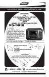
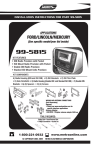
INSTALLATION INSTRUCTIONS FOR PART 95-3305
APPLICATIONS
CH EV ROLET
Avalanche 2007-10/Equinox 2007-09
Express Van 2008-10/Impala 2006-10
Monte Carlo 2006-07/Tahoe 2007-11
Silverado 2007-11 (Excluding Classic Models)
Suburban 2007-10/Traverse 2009-11
BUICK Enclave 2008-11, Lucerne 2006-10
GMC Acadia 2007-11
HUMMER H2 2008-09
Savanna 2008-10
PONTIAC Torrent 2007-09
Sierra Denaili 2007-11 (Excluding Classic Models) SATURN Outlook 2007-09/Vue 2008-09
Yukon Denali/XL 2007-10
95-3305
KIT FEATURES
• Double DIN Radio Provision
• Stacked ISO Units Provision
KIT COMPONENTS
A) Double DIN Trim Plate B) Double DIN Brackets
A
B
WIRING AND ANTENNA CONNECTIONS
(Sold Separately)
Wiring Harness:
• See www.metraonline.com for specific interface
Antenna Adapter:
• 40-CR10 - Chrysler antenna adapter 2002-up
TOOLS REQUIRED:
Small Flat Blade Screwdriver • Panel Removal Tool
• Phillips Screwdriver • Socket Set • Torx Driver • Allen Wrench
1-800-221-0932
www.metraonline.com
© COPYRIGHT 2004-2011 METRA ELECTRONICS CORPORATION
95-3305
TABLE OF CONTENTS
Dash Disassembly
- Chevrolet Impala 2006-2010. . . . . . . . . . . . . . . . . . . . . . . . . . . . . . . . . . . . . . . . . . . . . . . . . . 1
- Chevrolet Monte Carlo 2006-2007 . . . . . . . . . . . . . . . . . . . . . . . . . . . . . . . . . . . . . . . . . . . . .1
- Buick Lucerne 2006-2010 . . . . . . . . . . . . . . . . . . . . . . . . . . . . . . . . . . . . . . . . . . . . . . . . . . . 1
- Chevrolet Avalanche 2007-2010 . . . . . . . . . . . . . . . . . . . . . . . . . . . . . . . . . . . . . . . . . . . . . . .2
- Chevrolet Silverado (Excluding Classic Models) 2007-2011 . . . . . . . . . . . . . . . . . . . . . .2
- Chevrolet Suburban 2007-2010 . . . . . . . . . . . . . . . . . . . . . . . . . . . . . . . . . . . . . . . . . . . . . . .2
- Chevrolet Tahoe 2007-2011 . . . . . . . . . . . . . . . . . . . . .. . . . . . . . . . . . . . . . . . . . . . . . . . . . . 2
- GMC Sierra/Denali (Excluding Classic Models) 2007-2011 . . . . . . . . . . . . . . . . . . . . . . 2
- GMC Yukon/XL Denali 2007-2010 . . . . . . . . . . . . . . . . . . . . . . . . .. . . . . . . . . . . . . . . . . . . . .2
- Chevrolet Express Van 2008-10/GMC Savanna 2008-10 . . . . . . . . . . . . . . . . . . . . . . . . . . . 3
- Suzuki XL-7 2007-2009 . . . . . . . . . . . . . . . . . . . . . . . . . . . . . . . . . . . . . . . . . . . . . . . . . . . . . .4
- Chevrolet Equinox 2007-09/Pontiac Torrent 2007-09 . . . . . . . . . . . . . . . . . . . . . . . . . . . . . 5
- Buick Enclave 2008-11/ GMC Acadia 2007-11/Saturn Outlook 2007-09 . . . . . . . . . . . . . . 6
- Chevy Traverse 2009-11 . . . . . . . . . . . . . . . . . . . . . . . . . . . . . . . . . . . . . . . . . . . . . . . . . . . . . 6
- Hummer H2 2008-2009 . . . . . . . . . . . . . . . . . . . . . . . . . . . . . . . . . . . . . . . . . . . . . . . . . . . . . .7
- Saturn Vue 2008-2009 . . . . . . . . . . . . . . . . . . . . . . . . .. . . . . . . . . . . . . . . . . . . . . . . . . . . . . .8
Kit Assembly
- Double DIN Radio Provision . . . . . . . . . . . . . . . . . . . . . . . . . . . . . . . . . . . . . . . . . . . . . . . . . . 9
- Stacked ISO Units Provision . . . . . . . . . . . . . . . . . . . . . . . . . . . . . . . . . . . . . . . . . . . . . . . . . 9
Final Assembly . . . . . . . . . . . . . . . . . . . . . . . . . . . . . . . . . . . . . . . . . . . . . . . . . . .10
*Note:
Refer also to the instructions included with the aftermarket radio.
KNOWLEDGE IS POWER
Enhance your installation and fabrication skills by
enrolling in the most recognized and respected
mobile electronics school in our industry.
Log onto www.installerinstitute.com or call
800-354-6782 for more information and take
steps toward a better tomorrow.
95-3305 DASH DISASSEMBLY
BUICK LUCERNE
CHEVY IMPALA / MONTE CARLO 2006-2010
1 Disconnect the negative battery terminal to prevent an accidental short
circuit.
2 Unclip and remove the trim panel
around radio and a/c control.
(Figure A)
A
3 Remove (6) 9/32” screws to extract
radio and a/c control from sub dash.
(Figure B)
B
Continue to kit assembly.
1
95-3305 DASH DISASSEMBLY
SILVERADO (Excluding Classic Models)/SUBURBAN
CHEVY AVALANCHE/TAHOE
GMC YUKON/SIERRA (Excluding Classic Models) 2007-11
*Note: Refer also to the instructions included with the aftermarket radio.
A
1 Disconnect the negative battery terminal to prevent an accidental short circuit.
2 Unclip and remove radio trim panel.
(Figure A)
3 Remove (2) 8mm screws securing
switch panel below climate controls.
Unplug and remove switch panel.
(Figure B)
B
4 Remove (2) 8mm screws securing climate controls. Unplug and remove climate controls. (Figure B)
5 Remove (4) 9/32” screws securing
radio. Unplug and remove the radio.
(Figure C)
Continue to kit assembly.
C
2
95-3305 DASH DISASSEMBLY
CHEVY EXPRESS VAN / GMC SAVANNA 2008-10
*Note: Refer also to the instructions included with the aftermarket radio.
1 Disconnect the negative battery terminal to prevent an accidental short circuit.
2 Remove (2)10mm bolts from below knee bolster under steering column and remove
panel.
3 Remove (2)10mm bolts from panel below passenger dash airbag and remove panel.
4 Unsnap and remove radio and instrument cluster panel. (May not be necessary to
completely remove radio and instrument cluster panel to access radio.)
5 Remove (4) 9/32” bolts to remove radio.
Continue to kit assembly.
3
95-3305 DASH DISASSEMBLY
SUZUKI XL-7 2007-09
*Note: Refer also to the instructions included with the aftermarket radio.
A
1 Disconnect the negative battery terminal to prevent an accidental short circuit.
2 Press in on sides of the shifter boot to
release it from the shifter trim panel.
(Figure A)
3 Lift the boot up to access the Allen
screw securing the shifter knob to the
shifter lever. Loosen the Allen screw
and remove the shifter knob.
B
4 Remove (1) torx screw from the shifter
trim panel (Figure C), then using a
panel removal tool unsnap the shifter
trim panel. Unplug and remove the
panel. (Figure D)
C
5 Using a panel removal tool unsnap
the radio trim panel. Unplug and
remove the panel. (Figure E)
6 Remove (4) 9/32” screws securing
the radio. Unplug and remove the
radio.
Continue to kit assembly.
D
E
X
AU
D
REV
ND
BA
SEEK
FW
SEEK
X
AU
R
GER
EN
SS
PA
103:5
12:02
4
AI
G
BA
95-3305 DASH DISASSEMBLY
CHEVROLET EQUINOX 2007-09
PONTIAC TORRENT 2007-09
*Note: Refer also to the instructions included with the aftermarket radio.
A
1 Disconnect the negative battery terminal to prevent an accidental short
circuit.
2 Unsnap panel below power window
switch and remove. Note: This allows
you to unplug the window switch easier. (Figure A)
3 Unsnap and remove entire panel surrounding radio and shifter. (Figure B)
4 Remove (4) 9/32 screws securing
radio. Unplug and remove the radio.
(Figure C)
B
Continue to kit assembly.
C
5
95-3305 DASH DISASSEMBLY
BUICK ENCLAVE 2008-11 / GMC ACADIA 2007-11
SATURN OUTLOOK 2007-09
*Note: Refer also to the instructions included with the aftermarket radio.
BUICK ENCLAVE / CHEVY TRAVERSE
1 Disconnect the negative battery terminal to prevent an accidental short circuit.
2 Unclip the radio trim panel including
the climate controls. Unplug the climate controls and remove the panel.
(See drawings)
3 Remove (4) 9/32 screws securing the
radio. Unplug and remove the radio.
Continue to kit assembly.
GMC ACADIA
SATURN OUTLOOK
6
95-3305 DASH DISASSEMBLY
HUMMER H2 2008-09
*Note: Refer also to the instructions included with the aftermarket radio.
A
1 Disconnect the negative battery terminal to prevent an accidental short circuit.
2 Unclip the radio trim panel including
the a/c vents. Unplug any harnesses
connected to the panel and remove the
panel. (Figure A)
3 Remove (4) 9/32” screws securing the
climate controls. Unplug and remove
the climate controls.
4 Remove (4) 9/32 screws securing the
radio. Unplug and remove the radio.
Continue to kit assembly.
7
95-3305 DASH DISASSEMBLY
SATURN VUE 2008-09
*Note: Refer also to the instructions included with the aftermarket radio.
1 Disconnect the negative battery terminal to prevent an accidental short circuit.
A
2 Unclip and remove the trim panel on
top of the radio trim panel. (Figure A)
3 Remove (2) Phillips screws exposed
under panel removed in step 2.
(Figure B)
4 Unclip and remove the radio trim panel
including the a/c vents. (Figure B)
5 Unclip and remove the trim panel
surrounding the shifter including the
climate controls. (Figure C)
6 Remove (4) 9/32 screws securing the
radio. Unplug and remove the radio.
B
Continue to kit assembly.
C
8
95-3305 KIT ASSEMBLY
DOUBLE DIN RADIO PROVISION
*Note: Refer also to the instructions included with the aftermarket radio.
NOTE: XL-7 ONLY
Trim top corners of radio housing.
(Figure A)
B
A
1 Slide the appropriate bracket into the
trim plate aligning the holes in the
trim plate to the clips on the bracket.
(Figure B)
C
2 Slide the DDIN radio unit into the trim
plate bracket assembly and secure the
unit to the kit using the screws supplied with the head unit. (Figure C)
STACKED ISO UNITS PROVISION
NOTE: XL-7 ONLY
Trim top corners of radio housing.
(Figure A)
A
1 Slide the appropriate bracket into the
trim plate aligning the holes in the
trim plate to the clips on the bracket.
2 Slide the stacked ISO DIN units into the
trim plate bracket assembly and
secure the units to the kit using the
screws supplied with the head units.
(Figure C)
Continue to final assembly.
9
B
C
95-3305 FINAL ASSEMBLY
FINAL ASSEMBLY
A
(A) Strip wire ends back 1/2"
B
B) Twist ends together
C) Solder
C
D) Tape
D
1 Locate the factory wiring harness in the dash. Metra recommends using the
proper mating adapter and making connections as shown. (Isolate and individually tape off the ends of any unused wires to prevent electrical short circuit.)
2 Re-connect the negative battery terminal and test the unit for proper operation.
3 Reassemble radio and dash assemblies in reverse order of disassembly.
FINAL WIRING CONNECTIONS
Make wiring connections using the EIA color code chart shown below and the instructions included with the
head unit. Metra recommends making connections as shown below; Strip, Splice, Solder, Tape. Isolate and
individually tape off ends of any unused wires to prevent electrical short circuit.
METRA / EIA WIRING CODE
12V Ignition / Acc. . . . . . . . . . Red
Right Front (+) . . . . . . . . . . . . Gray
12V Batt / Memory. . . . . . . . . Yellow
Right Front (-). . . . . . . . . . . . . Gray/ Black
Ground. . . . . . . . . . . . . . . . . . Black*
Left Front (+) . . . . . . . . . . . . . White
Power Antenna. . . . . . . . . . . . Blue
Left Front (-). . . . . . . . . . . . . . White / Black
Amp Turn-On . . . . . . . . . . . . . Blue / White
Right Rear (+) . . . . . . . . . . . . Violet
Amp Ground. . . . . . . . . . . . . . Black / White
Right Rear (-) . . . . . . . . . . . . . Violet / Black
Illumination . . . . . . . . . . . . . . Orange
Left Rear (+) . . . . . . . . . . . . . Green
Dimmer . . . . . . . . . . . . . . . . . Orange / White
*NOTE: When a Black wire is not present, ground radio to vehicle chassis.
All colors may not be present on all leads due to manufacturer’s specifications.
REV. 11/22/10 © COPYRIGHT 2004-2010 METRA ELECTRONICS CORPORATION INST95-3305
10
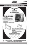
INSTRUCCIONES DE INSTALACIÓN PARA LA PIEZA 95-3305
APLICACIONES
CHEVROLET
Avalanche 2007-10/Equinox 2007-09
Express Van 2008-10/Impala 2006-10
Monte Carlo 2006-07/Tahoe 2007-11
Silverado 2007-11 (excl. Classic models)
Suburban 2007-10/Traverse 2009-11
BUICK Enclave 2008-11, Lucerne 2006-10
GMC Acadia 2007-11
Savanna 2008-10
Sierra/Denali 2007-11 (excluding classic models)
Yukon/Denali/XL 2007-10
HUMMER H2 2008-09
PONTIAC Torrent 2007-09
SATURN Outlook 2007-09/Vue 2008-09
SUZUKI XL7 2007-09
95-3305
CARACTERÍSTICAS DEL KIT
• Accesorio para radio DIN doble
• Accesorio para unidades ISO apiladas
COMPONENTES DEL KIT
A) Placa de terminación DIN doble B) Soportes DIN dobles
A
B
CONEXIONES DE CABLEADO Y ANTENA
(se venden por separado)
Arnés del cableado:
• Vea www.metraonline.com para la interfaz específica
Adaptador de antena:
• Adaptador de antena Chrysler 40-CR10 2002 y modelos
HERRAMIENTAS REQUERIDAS:
• Destornillador de hoja plana pequeño • Herramienta para retirar paneles
• Destornillador Phillips • Juego de soportes • Destornillador Torx • Llave Allen
1-800-221-0932
www.metraonline.com
© COPYRIGHT 2004-2010 METRA ELECTRONICS CORPORATION
95-3305
INDICE
Desmontaje del tablero
- Chevrolet Impala 2006-2010. . . . . . . . . . . . . . . . . . . . . . . . . . . . . . . . . . . . . . . . . . . . . . . . . . 1
- Chevrolet Monte Carlo 2006-2007 . . . . . . . . . . . . . . . . . . . . . . . . . . . . . . . . . . . . . . . . . . . . .1
- Buick Lucerne 2006-2010 . . . . . . . . . . . . . . . . . . . . . . . . . . . . . . . . . . . . . . . . . . . . . . . . . . . 1
- Chevrolet Avalanche 2007-2010 . . . . . . . . . . . . . . . . . . . . . . . . . . . . . . . . . . . . . . . . . . . . . . .2
- Chevrolet Silverado (noincluyelosmodelosclásicos) 2007-2011 . . . . . . . . . . . . . . . . . . . . . . .2
- Chevrolet Suburban 2007-2011 . . . . . . . . . . . . . . . . . . . . . . . . . . . . . . . . . . . . . . . . . . . . . . .2
- Chevrolet Tahoe 2007-2011 . . . . . . . . . . . . . . . . . . . . .. . . . . . . . . . . . . . . . . . . . . . . . . . . . . .2
- GMC Sierra (noincluyelosmodelosclásicos) 2007-2011 . . . . . . . . . . . . . . . . . . . . . . . . . . . .2
- GMC Yukon/XL Denali 2007-2010 . . . . . . . . . . . . . . . . . . . . . . . . .. . . . . . . . . . . . . . . . . . . . .2
- Chevrolet Express Van 2008-10/GMC Savanna 2008-10 . . . . . . . . . . . . . . . . . . . . . . . . . . . 3
- Suzuki XL-7 2007-2009 . . . . . . . . . . . . . . . . . . . . . . . . . . . . . . . . . . . . . . . . . . . . . . . . . . . . . .4
- Chevrolet Equinox 2007-09/Pontiac Torrent 2007-09 . . . . . . . . . . . . . . . . . . . . . . . . . . . . . 5
- Buick Enclave 2008-10/ GMC Acadia 2007-11/Saturn Outlook 2007-09 . . . . . . . . . . . . . . 6
- Chevy Traverse 2009-11 . . . . . . . . . . . . . . . . . . . . . . . . . . . . . . . . . . . . . . . . . . . . . . . . . . . . . 6
- Hummer H2 2008-2009 . . . . . . . . . . . . . . . . . . . . . . . . . . . . . . . . . . . . . . . . . . . . . . . . . . . . . .7
- Saturn Vue 2008-2009 . . . . . . . . . . . . . . . . . . . . . . . . .. . . . . . . . . . . . . . . . . . . . . . . . . . . . . .8
Montaje del kit
- Accesorio para radio DIN doble . . . . . . . . . . . . . . . . . . . . . . . . . . . . . . . . . . . . . . . . . . . . . . . 9
- Accesorio para unidades ISO apiladas . . . . . . . . . . . . . . . . . . . . . . . . . . . . . . . . . . . . . . . . 9
Montaje final . . . . . . . . . . . . . . . . . . . . . . . . . . . . . . . . . . . . . . . . . . . . . . . . . . . . .10
*Nota:
Asimismo, remítase a las instrucciones incluidas con el radio de posventa.
KNOWLEDGE IS POWER
Enhance your installation and fabrication skills by
enrolling in the most recognized and respected
mobile electronics school in our industry.
Log onto www.installerinstitute.com or call
800-354-6782 for more information and take
steps toward a better tomorrow.
95-3305 DESMONTAJE DEL TABLERO
BUICK LUCERNE
CHEVY IMPALA / MONTE CARLO 2006-2010
1 Desconecte el terminal negativo de la
batería, a fin de evitar un cortocircuito
accidental.
2 Desenganche y retire el panel de terminación que rodea el control del radio y
del aire acondicionado. (Figura A)
A
3 Retire (6) tornillos de 9/32 in para
extraer el control del radio y del aire
acondicionado del subtablero. (Figura B)
B
Continúe con el montaje del kit.
1
95-3305 DESMONTAJE DEL TABLERO
SILVERADO (noincluyemodelosclásicos)/SUBURBAN
CHEVY AVALANCHE/TAHOE
GMC YUKON/SIERRA (noincluyemodelosclásicos) 2007-10
Nota: Asimismo, remítase a las instrucciones incluidas con el radio de posventa.
A
1 Desconecte el terminal negativo de la
batería, a fin de evitar un cortocircuito
accidental.
2 Desenganche y retire el panel de terminación del radio. (Figura A)
3 Retire (2) tornillos de 8 mm que sujetan
el panel de interruptores debajo de los
controles de clima. Desenchufe y retire
el panel de interruptores. (Figura B)
B
4 Retire (2) tornillos de 8 mm que sujetan
los controles de clima. Desenchufe y
retire los controles de clima. (Figura B)
5 Retire (4) tornillos de 9/32 in que sujetan el radio. Desenchufe y retire el
radio. (Figura C)
Continúe con el montaje del kit.
C
2
95-3305 DESMONTAJE DEL TABLERO
CHEVY EXPRESS VAN / GMC SAVANNA 2008-10
*Nota: Asimismo, remítase a las instrucciones incluidas con el radio de posventa.
1 Desconecte el terminal negativo de la batería, a fin de evitar un cortocircuito
accidental.
2 Retire (2) pernos de 10 mm de la parte de abajo del amortiguador para las rodillas
que se encuentra debajo de la columna de la dirección y retire el panel.
3 Retire (2) pernos de 10 mm del panel que se encuentra debajo del airbag del
tablero del pasajero y retire el panel.
4 Quite a presión y retire el panel del radio y del grupo de instrumentos. (Es posible
que no sea necesario retirar completamente el panel del radio y del grupo de
instrumentos para tener acceso al radio).
5 Retire (4) pernos de 9/32 in para retirar el radio.
Continúe con el montaje del kit.
3
95-3305 DESMONTAJE DEL TABLERO
SUZUKI XL-7 2007-09
*Nota: Asimismo, remítase a las instrucciones incluidas con el radio de posventa.
1 Desconecte el terminal negativo de la
batería, a fin de evitar un cortocircuito
accidental.
2 Presione los lados de la cubierta de protección de la palanca de velocidades
para liberarla del panel de terminación de
la palanca de velocidades. (Figura A)
3 Levante la cubierta de protección para
poder acceder al tornillo Allen, que sujeta la perilla de la palanca de velocidades
a la palanca de velocidades. Afloje el
tornillo Allen y retire la perilla de la
palanca de velocidades. (Figura B)
4 Retire (1) tornillo Torx del panel de terminación de la palanca de velocidades
(Figura C), y luego use una herramienta
para retirar paneles para quitar a presión el panel de terminación de la
palanca de velocidades. Desenchufe y
retire el panel. (Figura D)
5 Con una herramienta para retirar paneles, quite a presión el panel de terminación del radio. Desenchufe y retire el
panel. (Figura E)
6 Retire (4) tornillos de 9/32 in que
sujetan el radio. Desenchufe y retire
el radio.
A
B
C
Continúe con el montaje del kit.
D
E
X
AU
D
REV
ND
BA
SEEK
FW
SEEK
X
AU
R
GER
EN
SS
PA
103:5
12:02
4
AI
G
BA
95-3305 DESMONTAJE DEL TABLERO
CHEVROLET EQUINOX 2007-09
PONTIAC TORRENT 2007-09
*Nota: Asimismo, remítase a las instrucciones incluidas con el radio de posventa.
A
1 Desconecte el terminal negativo de la
batería, a fin de evitar un cortocircuito
accidental.
2 Quite a presión el panel que se
encuentra debajo del interruptor del
alzacristales y retírelo. Nota: Esto le
permite desenchufar el interruptor de
las ventanas con mayor facilidad.
(Figura A)
3 Quite a presión y retire el panel completo que rodea el radio y la palanca
de velocidades. (Figura B)
B
4 Retire (4) tornillos de 9/32 in que sujetan el radio. Desenchufe y retire el
radio. (Figura C)
Continúe con el montaje del kit.
C
5
95-3305 DESMONTAJE DEL TABLERO
BUICK ENCLAVE 2008-11 / GMC ACADIA 2007-11
SATURN OUTLOOK 2007-09
*Nota: Asimismo, remítase a las instrucciones incluidas con el radio de posventa.
BUICK ENCLAVE / CHEVY TRAVERSE
1 Desconecte el terminal negativo de la
batería, a fin de evitar un cortocircuito
accidental.
2 Desenganche el panel de terminación
del radio, incluidos los controles de
clima. Desenchufe los controles de
clima y retire el panel. (Vea los dibujos)
3 Retire (4) tornillos de 9/32 in que sujetan el radio. Desenchufe y retire el
radio.
Continúe con el montaje del kit.
GMC ACADIA
SATURN OUTLOOK
6
95-3305 DESMONTAJE DEL TABLERO
HUMMER H2 2008-09
*Nota: Asimismo, remítase a las instrucciones incluidas con el radio de posventa.
A
1 Desconecte el terminal negativo de la
batería, a fin de evitar un cortocircuito
accidental.
2 Desenganche el panel de terminación
del radio, incluidas las rejillas de ventilación del aire acondicionado.
Desenchufe cualquier arnés que esté
conectado al panel y retire el panel.
(Figura A)
3 Retire (4) tornillos de 9/32 in que sujetan los controles de clima. Desenchufe
y retire los controles de clima.
4 Retire (4) tornillos de 9/32 in que sujetan el radio. Desenchufe y retire el
radio.
Continúe con el montaje del kit.
7
95-3305 DESMONTAJE DEL TABLERO
SATURN VUE 2008-09
*Nota: Asimismo, remítase a las instrucciones incluidas con el radio de posventa.
1 Desconecte el terminal negativo de la
batería, a fin de evitar un cortocircuito
accidental.
2 Desenganche y retire el panel de terminación que está en la parte superior
del panel de terminación del radio.
(Figura A)
3 Retire (2) tornillos Phillips expuestos
que se encuentran debajo del panel
que se retiró en el paso 2. (Figura B)
4 Desenganche y retire el panel de terminación del radio, incluidas las rejillas de ventilación del aire acondicionado. (Figura B)
A
5 Desenganche y retire el panel de terminación que rodea la palanca de velocidades, incluidos los controles de clima.
(Figura C)
6 Retire (4) tornillos de 9/32 in que sujetan
el radio. Desenchufe y retire el radio.
B
Continúe con el montaje del kit.
C
8
95-3305 MONTAJE DEL KIT
ACCESORIO PARA RADIO DIN DOBLE
*Nota: Asimismo, remítase a las instrucciones incluidas con el radio de posventa.
NOTA: SOLO PARA XL-7
Esquinas superiores de las terminaciones
del alojamiento del radio. (Figura A)
B
A
1 Deslice el soporte adecuado en la placa
de terminación alineando los orificios
de la placa de terminación con los ganchos del soporte. (Figura B)
2 Deslice la unidad del radio DDIN en el
conjunto del soporte de la placa de terminación y sujete la unidad en el kit
usando los tornillos suministrados con la
unidad central. (Figura C)
C
ACCESORIO PARA UNIDADES ISO APILADAS
NOTA: SOLO PARA XL-7
Esquinas superiores de las terminaciones
del alojamiento del radio. (Figura A)
A
1 Deslice el soporte adecuado en la placa
de terminación alineando los orificios de
la placa de terminación con los ganchos
del soporte. (Figura B)
2 Deslice las unidades DIN ISO apiladas
en el conjunto del soporte de la placa
de terminación y sujete las unidades al
kit usando los tornillos suministrados
con las unidades centrales. (Figura C)
Continúe con el montaje final.
9
B
C
95-3305 MONTAJE FINAL
MONTAJE FINAL
A
A) Pele 1/2 in de los extremos de los cables.
B
B) Tuerza los extremos juntos.
C) Suelde.
C
D) Encinte.
D
1 Ubique el arnés del cableado de fábrica en el tablero. Metra recomienda usar el
adaptador de acoplamiento adecuado y realizar las conexiones como se muestra.
(Aísle y encinte individualmente los extremos de cualquier cable que no esté en
uso, a fin de evitar un cortocircuito eléctrico).
2 Vuelva a conectar el terminal negativo de la batería y pruebe la unidad para verificar que funcione correctamente.
3 Vuelva a montar los conjuntos del radio y tablero en forma inversa al desmontaje.
CONEXIONES DE CABLEADO FINALES
Realice las conexiones de cableado utilizando el cuadro de códigos de colores de la Alianza de industrias
electrónicas (Electronic Industries Alliance, EIA) que se muestra a continuación y las instrucciones incluidas
con la unidad central. Metra recomienda realizar las conexiones como se muestra a continuación: Pelar,
empalmar, soldar, encintar. Aísle y encinte individualmente los extremos de cualquier cable que no esté en
uso, a fin de evitar un cortocircuito eléctrico.
CÓ DIGO DE CABLEADO DE METRA/EIA
Ignición de 12 V/Acc. . . . . . . . . . Rojo
Batería de 12 V/memoria.........Amarillo
Conexión a tierra..................Negro*
Antena eléctrica............Azul
Encendido Amp..............Azul/blanco
Conexión a tierra Amp................ Negro/blanco
Iluminación..............Naranja
Atenuador.................Naranja/blanco
Parte delantera derecha (+)............Gris
Parte delantera derecha (-).............Gris/negro
Parte delantera izquierda (+).............Blanco
Parte delantera izquierda (-)..............Blanco/negro
Parte trasera derecha (+)............ Violeta
Parte trasera derecha (-) ............. Violeta/negro
Parte trasera izquierda (+).............Verde
Parte trasera izquierda (-)..............Verde/negro
*NOTE: Cuando no haya un cable negro, conecte a tierra el radio con el chasis del vehículo.
Es posible que no se encuentren todos los colores en todos los conductores como consecuencia de las
especificaciones del fabricante.
REV. 11/22/10 © COPYRIGHT 2004-2010 METRA ELECTRONICS CORPORATION INST95-3305
10