1
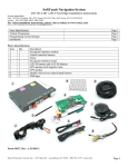
INSTALLATION INSTRUCTIONS FOR PART 99-5815
APPLICATIONS
FORD/LINCOLN/MERCURY
(See specific model/year list inside)
99-5815
KIT FEATURES
• DIN Radio Provision with Pocket
• ISO Mount Radio Provision with Pocket
• Double DIN Radio Provision
• Stacked ISO Mount Units Provision
KIT COMPONENTS
A) Radio Housing (DIN and ISO DIN) • B) ISO Brackets • C) ISO Trim Plate
• D) Side brackets • E) Radio Housing (Double DIN and Stacked ISO DIN) • F) Double DIN
Brackets • G) (8) Spacers • H) (4) Screws
D
F
E
C
B
A
G
H
WIRING AND ANTENNA CONNECTIONS
(Sold Separately)
Harness:
• Please see www.metraonline.com for
specific interface applications
Antenna Adapter:
• 40-CR10 - Chrysler antenna adapter 2002-up
TOOLS REQUIRED:
Cutting Tool • Panel Removal Tool
• Phillips Screwdriver • Socket Set
1-800-221-0932
© COPYRIGHT 2004-2009
www.metraonline.com
METRA ELECTRONICS CORPORATION
99-5815
TABLE OF CONTENTS
Dash Disassembly
Ford Edge 2007..............................................................................................................1
Ford F-150 2004-2006 / Expedition 2007 .....................................................................1
Lincoln Mark LT 2005-2007 ...........................................................................................1
Ford Mustang 2005-2007...............................................................................................2
Ford Five Hundred 2005-2007........................................................................................3
Mercury Sable 2008 ......................................................................................................3
Ford Taurus 2008 ...........................................................................................................3
Mercury Montego 2005-2007.........................................................................................3
Ford Fusion 2006-2007..................................................................................................4
Mercury Milan 2006-2007............................................................................................. 4
Ford Freestyle 2005-2007..............................................................................................5
Ford Taurus X 2008 .......................................................................................................5
Ford Freestar 2004-2007...............................................................................................6
Mercury Monterey 2004-2007 ...................................................................................... 6
Ford Focus 2005-2007...................................................................................................7
Ford Explorer 2006-07.................................................................................................. 8
Ford Explorer Sport Trac 2006-2007..............................................................................8
Mercury Mountaineer 2006-2007..................................................................................8
Ford F Series Super Duty 2005-2007.............................................................................9
Ford Super Duty 2008..................................................................................................10
Lincoln Navigator 2007................................................................................................11
Lincoln MKX 2007 .......................................................................................................12
Lincoln MKZ 2007. ..................................................................................................13,14
Lincoln Zephyr 2006 .............................................................................................. 13,14
Kit Assembly
DIN Radio Provision with Pocket.................................................................15
ISO Mount Radio Provision with Pocket......................................................16
Double DIN Radio Provision.........................................................................................17
Stacked ISO Mount Units Provision..............................................................................18
Final Assembly ............................................................................................................19
*Note: Refer also to the instructions
included with the aftermarket radio.
KNOWLEDGE IS POWER
Enhance your installation and fabrication skills
by enrolling in the most recognized and respected
mobile electronics school in our industry.
Log onto www.installerinstitute.com
or call 800-354-6782 for more information
and take steps toward a better tomorrow.
99-5815 DASH DISASSEMBLY
FORD F-150 2004-2007
LINC0LN MARK LT 2005-2006
FORD EXPEDITION 2007
FORD EDGE 2007-09
A
1 Disconnect the negative battery terminal to prevent an accidental short
circuit.
2 Unsnap and remove entire panel surrounding the radio and climate controls. (Figure A)
3 Remove (4) 9/32" screws to remove
the factory radio. (Figure B)
Continue to kit assembly.
B
1
99-5815 DASH DISASSEMBLY
FORD MUSTANG 2005-2009
*Note: Refer also to the instructions included with the aftermarket radio.
A
1 Disconnect the negative battery terminal to prevent an accidental short circuit.
2 Remove the small rectangular shifter
lever trim panel if equipped. (Figure A)
3 Remove (2) Phillips screws from under
the center armrest at the back of the
shifter trim panel (including cup
holders). (Figure B)
B
4 Unclip and remove panel. (Figure B)
5 Unclip and remove the (2) center
stack trim panels from the left and
right side of the radio and climate
controls. (Figure C)
6 Remove (6) 9/32” screws from center trim panel surrounding the radio
and climate controls then unclip and
remove panel. (Figure D)
C
7 Remove (4) 9/32” screws from the
radio to remove. (Figure E)
Continue to final assembly.
E
D
2
99-5815 DASH DISASSEMBLY
FORD FIVE-HUNDRED 2005-2007/FORD TAURUS 2008-09
MERCURY MONTEGO 2005-2007, MERCURY SABLE 2008-09
*Note: Refer also to the instructions included with the aftermarket radio.
1 Disconnect the negative battery terminal to prevent an accidental short circuit.
A
2 Unclip and remove the small rectangular trim around shift lever. (Figure A)
3 Unclip and remove the entire panel
(including cup holders) surrounding the
shift lever. (Figure B)
B
4 Remove (2) 9/32” screws at the bottom
of the center radio/climate control
panel. (Figure C)
5 Unclip and remove the center panel.
(Figure D)
6 Remove (4) 9/32” screws from the
radio to remove. (Figure E)
C
Continue to final assembly.
D
E
3
99-5815 DASH DISASSEMBLY
FORD FUSION 2006-2007
MERCURY MILAN 2006-2008
A
1 Disconnect the negative battery terminal to prevent an accidental short
circuit.
2 Unsnap and remove entire panel surrounding the radio and climate controls. (Figure A)
3 Remove (4) 9/32" screws to remove
the factory radio. (Figure B)
Continue to kit assembly.
B
4
99-5815 DASH DISASSEMBLY
FORD FREESTYLE 2005-2007
FORD TAURUS X 2008-09
A
1 Disconnect the negative battery terminal to prevent an accidental short
circuit.
2 Unclip and remove entire panel surrounding the radio and a/c controls.
(Figure A)
3 Remove (4) 9/32” screws from radio
to remove. (Figure B)
Continue to kit assembly.
B
5
99-5815 DASH DISASSEMBLY
FORD FREESTAR 2004-2007
MERCURY MONTEREY 2004-2007
A
1 Disconnect the negative battery terminal to prevent an accidental short
circuit.
2 Unsnap and remove entire panel surrounding the radio and climate controls. (Figure A)
3 Remove (4) 9/32" screws to remove
the factory radio. (Figure B)
Continue to kit assembly.
B
6
99-5815 DASH DISASSEMBLY
FORD FOCUS 2005-2007
A
1 Disconnect the negative battery terminal to prevent an accidental short
circuit.
2 Unsnap and remove entire panel surrounding the radio and climate controls. (Figure A)
3 Remove (4) 9/32" screws to remove
the factory radio. (Figure B)
Continue to kit assembly.
B
7
99-5815 DASH DISASSEMBLY
FORD EXPLORER/EXPLORER SPORT TRAC 2006-2009
MERCURY MOUNTAINEER 2006-2009
A
1 Disconnect the negative battery terminal to prevent an accidental short
circuit.
2 Open center console and remove (2)
Phillips screws then unclip and
remove entire panel surrounding
shifter. (Figure A)
B
C
3 Remove dash panel surrounding radio
to access the factory radio screws.
(Figure B)
4 Remove (4) 9/32" screws to remove
the factory radio. (Figure B)
Continue to kit assembly.
8
99-5815 DASH DISASSEMBLY
FORD F SERIES SUPER DUTY 2005-2007
1 Disconnect the negative battery terminal to prevent an accidental short
circuit.
2 Unsnap and remove entire panel
surrounding the radio and climate
controls. (Figure A)
A
B
3 Remove (4) 9/32" screws to remove
the factory radio. (Figure B)
Continue to kit assembly.
9
99-5815 DASH DISASSEMBLY
FORD SUPER DUTY 2008-09
1 Disconnect the negative battery terminal to prevent an accidental short
circuit.
2 Unclip and remove the power outlet
panel and the blank panel on the left
and right side of the radio trim panel.
(Figure A)
A
3 Remove the (2) 9/32” screws exposed
behind the two panels remove in
step 2.
4 Unclip and remove the entire radio
trim panel including the a/c control
and vents.
5 Remove (4) 9/32” screws securing
the radio.
Continue to kit assembly
10
99-5815 DASH DISASSEMBLY
LINCOLN NAVIGATOR 2007-09
A
1 Disconnect the negative battery terminal to prevent an accidental short
circuit.
2 Unclip and remove the panel surrounding the shifter. (Figure A)
3 Remove (2) 9/32” screws from the
bottom of the radio/climate control
trim panel. (Figure B)
4 Unclip and remove the entire panel
surrounding the radio and including
the climate controls. (Figure B)
5 Remove (4) 9/32” screws securing
the radio. Unplug and remove the
Radio.
B
Continue to kit assembly.
11
99-5815 DASH DISASSEMBLY
LINCOLN MKX 2007-09
A
1 Disconnect the negative battery terminal to prevent an accidental short
circuit.
2 Open center console lid and unclip and
remove the center console trim panel
surrounding the shifter. (Figure A)
3 Remove (2) Phillips screws from the
storage bin then unclip and remove
the bin. (Figure B)
4 Unclip and remove the upper and
lower center trim panel as one
assembly. (Figure C)
B
5 Remove (4) 9/32” screws securing
the radio. Unplug and remove the
Radio.
Continue to kit assembly.
C
12
99-5815 DASH DISASSEMBLY
LINCOLN MKZ 2007-09/LINCOLN ZEPHYR 2006
A
1 Disconnect the negative battery terminal to prevent an accidental short
circuit.
2 Unclip and remove the top of the
center console. (Figure A)
3 Open ashtray door and remove ashtray then remove (1) Phillips screw
from inside ashtray cavity. Close ashtray door.
B
4 Unclip and remove the climate control
and trim panel assembly starting at
the bottom edge. (Figure B)
5 Open the climate control vents and
pull straight outward to remove.
(Figure C)
Continue on page 14.
C
13
99-5815 DASH DISASSEMBLY
LINCOLN MKZ 2007-09/LINCOLN ZEPHYR 2006
D
6 Remove (2) 9/32” from the bottom of
the radio trim panel assembly and (2)
9/32” screws from inside the vents.
(Figure D)
7 Unclip the radio trim panel/radio
assemmbly. Unplug and remove
assembly. (Figure D)
8 Remove (4) 9/32” screws securing the
radio to the trim panel and remove the
radio. (Figure E)
E
Continue to kit assembly.
14
99-5815 KIT ASSEMBLY
DIN RADIO PROVISION WITH POCKET
NOTE: Refer also to the instructions included with the aftermarket radio.
1A
1 (a) For the Ford Edge/Expedition
2007, Explorer 2006-07, Fusion
2006-07, Mustang 2007 and the
Super Duty 2008 attach the included spacers to the back of the radio
housing mounting tabs. (Figure 1A)
NOTE: Use the screws supplied with this
kit to mount the radio housing in the
vehicles that require the spacers.
1B
(b) For the Ford Freestar 2004-07,
Monterey 2004-07, Focus 200507, and the F Series Super Duty
2005-07, slide the included brackets
onto the sides of the radio housings
pocket from the back of the housing
forward. (Figure 1B)
If your vehicle is not listed above
move to step 2.
A
2 Slide the DIN cage into the Radio
Housing and secure by bending the
metal locking tabs outward. (Figure A)
B
3 Slide the aftermarket radio into the
cage until it snaps in place. (Figure B)
Continue to final assembly
15
99-5815 KIT ASSEMBLY
ISO MOUNT RADIO PROVISION WITH POCKET
NOTE: Refer also to the instructions included with the aftermarket radio.
1 (a) For the Ford Edge/Expedition
2007, Explorer 2006-07, Fusion
2006-07, Mustang 2007 and the
Super Duty 2008 attach the included spacers to the back of the radio
housing mounting tabs. (Figure 1A)
NOTE: Use the screws supplied with this
kit to mount the radio housing in the
vehicles that require the spacers.
1A
(b) For the Ford Freestar 2004-07,
Monterey 2004-07, Focus 2005-07,
and the F Series Super Duty 200507, slide the included brackets onto
the sides of the radio housings pocket
from the back of the housing forward.
(Figure 1B)
If your vehicle is not listed above
move to step 2.
1B
A
2 Mount the ISO Brackets to the head
unit with the screws supplied with
the unit. (Figure A)
B
3 Slide the head unit into the radio
opening until the side clips engage
(Figure B)
4 Snap the Trim Plate into the Radio
Housing. (Figure B)
Continue to final assembly
16
99-5815 KIT ASSEMBLY
DOUBLE DIN RADIO PROVISION
*Note: Refer also to the instructions included with the aftermarket radio.
1 For the 2007 Ford Edge/Expedition, 2006-07 Explorer/Fusion/Mercury
Milan, 2004-07 F-150, 2005-07 Five Hundred/Freestyle/Mustang/
Mercury Montego, 2005-07 Lincoln Mark LT and the 2008 Super Duty,
cut and remove the rear mounting tabs from the Double DIN Brackets
a. If your vehicle is not listed above move to step 2.
For the 2007 Ford Edge/Expedition,
2006-07 Explorer, 2006-07 Fusion,
2007 Mustang and the 2008 Super
Duty attach the included spacers to
the back of the radio housing mounting tabs.
a. If your vehicle is not listed above
move to step 3. (Figure A)
A
NOTE: Use the screws supplied with this kit to mount the radio housing in the vehicles that
require the spacers.
3 Attach the double DIN brackets to the radio housing. Note: The notch in the housing
should be on top. (Figure 3A,3B)
3A
3B
C
4 Slide the Double DIN radio into the
radio housing/bracket assembly and
secure the radio to the assembly using
the screws supplied with the radio.
(Figure C)
Continue to kit assembly.
17
99-5815 KIT ASSEMBLY
STACKED ISO MOUNT UNITS PROVISION
*Note: Refer also to the instructions included with the aftermarket radio.
1 For the 2007 Ford Edge/Expedition,
2006-07 Explorer/Fusion/
Mercury Milan, 2004-07 F-150,
2005-07 Five Hundred/
Freestyle/Mustang/Mercury
Montego, 2005-07 Lincoln Mark LT
and the 2008 Ford Super Duty, cut
and remove the rear mounting tabs
from the Double DIN Brackets.
a. If your vehicle is not listed above
move to step 2.
A
2 For the 2007 Ford Edge/Expedition,
2006-07 Ford Explorer, 2006-07
Ford Fusion, 2007 Mustang and
the 2008 Super Duty attach the
included spacers to the back of the
radio housing mounting tabs.
(Figure A)
a. If your vehicle is not listed above
move to step 3.
NOTE: Use the screws supplied with this
kit to mount the radio housing in the
vehicles that require the spacers.
3A
3B
3 Attach the double DIN brackets to the
radio housing. Note: The notch in the
housing should be on top.
(Figure 3A,3B)
4 Slide the ISO mount units into the
radio housing/bracket assembly and
secure the units to the assembly using
the screws supplied with the units.
(Figure C)
Continue to kit assembly.
18
C
99-5815 FINAL ASSEMBLY
FINAL ASSEMBLY
A
(A) Strip wire ends back 1/2"
B
B) Twist ends together
C) Solder
C
D) Tape
D
1 Locate the factory wiring harness in the dash. Metra recommends using the
proper mating adapter and making connections as shown. (Isolate and individually tape off the ends of any unused wires to prevent electrical short circuit.)
2 Re-connect the negative battery terminal and test the unit for proper operation.
3 Reassemble radio and dash assemblies in reverse order of disassembly.
NOTE: Use the screws supplied with this kit to mount the radio housing in the vehicles
that require the spacers.
FINAL WIRING CONNECTIONS
Make wiring connections using the EIA color code chart shown below and the instructions included with the
head unit. Metra recommends making connections as shown below; Strip, Splice, Solder, Tape. Isolate and
individually tape off ends of any unused wires to prevent electrical short circuit.
METRA / EIA WIRING CODE
12V Ignition / Acc. . . . . . . . . . Red
Right Front (+) . . . . . . . . . . . . Gray
12V Batt / Memory. . . . . . . . . Yellow
Right Front (-). . . . . . . . . . . . . Gray/ Black
Ground. . . . . . . . . . . . . . . . . . Black*
Left Front (+) . . . . . . . . . . . . . White
Power Antenna. . . . . . . . . . . . Blue
Left Front (-). . . . . . . . . . . . . . White / Black
Amp Turn-On . . . . . . . . . . . . . Blue / White
Right Rear (+) . . . . . . . . . . . . Violet
Amp Ground. . . . . . . . . . . . . . Black / White
Right Rear (-) . . . . . . . . . . . . . Violet / Black
Illumination . . . . . . . . . . . . . . Orange
Left Rear (+) . . . . . . . . . . . . . Green
Dimmer . . . . . . . . . . . . . . . . . Orange / White
Left Rear (-) . . . . . . . . . . . . . . Green / Black
*NOTE: When a Black wire is not present, ground radio to vehicle chassis.
All colors may not be present on all leads due to manufacturer’s specifications.
19
99-5815
NOTES
20
INSTRUCCIONES DE INSTALACIÓ N PARA LA PIEZA 95-8202
APLICACIONES
FORD/LI NCOLN/MERCU RY
(see specific model/year list inside)
99-5815
CARACTERÍSTICAS DEL KIT
• Accesorio para radio DIN con bolsillo
• Accesorio para radio de montaje ISO con bolsillo
• Accesorio para radio DIN doble
• Accesorio para unidades de montaje ISO apiladas
COMPONENTES DEL KIT
A) Alojamiento del radio (DIN y DIN ISO) • B) Soportes ISO • C) Placa de terminación
ISO • D) Soportes laterales • E) Alojamiento del radio (DIN doble y DIN ISO apilado)
• F) Soportes DIN dobles • G) (8) Espaciadores • H) (4) Tornillos
D
G
F
E
C
B
A
H
CONEXIONES DE CABLEADO Y ANTENA
(se venden por separado)
Arnés:
• Vea www.metraonline.com para las aplicaciones
de la interfaz específica
Adaptador de antena:
• Adaptador de antena Chrysler 40-CR10 2002
y modelos posteriores
HERRAMIENTAS REQUERIDAS:
• Herramienta de corte • Herramienta para retirar paneles
• Destornillador Phillips • Juego de soportes
1-800-221-0932
© COPYRIGHT 2004-2009
www.metraonline.com
METRA ELECTRONICS CORPORATION
99-5815
INDICE
Desmontaje del tablero
Ford Edge 2007..............................................................................................................1
Ford F-150 2004-2006 / Expedition 2007 .....................................................................1
Lincoln Mark LT 2005-2007 ...........................................................................................1
Ford Mustang 2005-2007...............................................................................................2
Ford Five Hundred 2005-2007........................................................................................3
Mercury Sable 2008 ......................................................................................................3
Ford Taurus 2008 ...........................................................................................................3
Mercury Montego 2005-2007.........................................................................................3
Ford Fusion 2006-2007..................................................................................................4
Mercury Milan 2006-2007............................................................................................. 4
Ford Freestyle 2005-2007..............................................................................................5
Ford Taurus X 2008 .......................................................................................................5
Ford Freestar 2004-2007...............................................................................................6
Mercury Monterey 2004-2007 ...................................................................................... 6
Ford Focus 2005-2007...................................................................................................7
Ford Explorer 2006-07.................................................................................................. 8
Ford Explorer Sport Trac 2006-2007..............................................................................8
Mercury Mountaineer 2006-2007..................................................................................8
Ford F Series Super Duty 2005-2007.............................................................................9
Ford Super Duty 2008..................................................................................................10
Lincoln Navigator 2007................................................................................................11
Lincoln MKX 2007 .......................................................................................................12
Lincoln MKZ 2007. ..................................................................................................13,14
Lincoln Zephyr 2006 .............................................................................................. 13,14
Montaje del kit
Accesorio para radio DIN con bolsillo.........................................................15
Accesorio para radio de montaje ISO con bolsillo..............................16
Accesorio para radio DIN doble...................................................................................17
Accesorio para unidades de montaje ISO apiladas.....................................................18
Montaje final ..............................................................................................................19
*Nota: Asimismo, remítase a las
instrucciones incluidas con el
radio de posventa.
Conocimiento es Poder
Convierta su hobby en una carrera en Installer Institute,
el líder educativo de la industria de dispositivos
electrónicos portátiles.
Regístrese en www.installerinstitute.com o llame al
800-354-6782 para obtener más información y empiece
su nueva carrera hoy mismo.
99-5815 DESMONTAJE DEL TABLERO
FORD F-150 2004-2007
LINC0LN MARK LT 2005-2006
FORD EXPEDITION 2007
FORD EDGE 2007-09
A
1 Desconecte el terminal negativo de la
batería, a fin de evitar un cortocircuito
accidental.
2 Quite a presión y retire todo el panel
que rodea el radio y los controles de
clima. (Figura A)
3 Retire (4) tornillos de 9/32 in para
retirar el radio de fábrica. (Figura B)
Continúe con el montaje del kit.
B
1
99-5815 DESMONTAJE DEL TABLERO
FORD MUSTANG 2005-2009
1
2
3
4
5
6
*Nota: Asimismo, remítase a las instrucciones incluidas con el radio de
posventa.
Desconecte el terminal negativo de la
A
batería, a fin de evitar un cortocircuito
accidental.
Retire el panel de terminación pequeño
rectangular de la palanca de velocidades, si corresponde. (Figura A)
Retire (2) tornillos Phillips que se
encuentran debajo del apoyabrazos
central en la parte posterior del panel
de terminación de la palanca de velociB
dades (incluidos los portavasos).
(Figura B)
Desenganche y retire el panel. (Figura B)
Desenganche y retire los (2) paneles
de terminación apilados centrales de
los lados izquierdo y derecho del
radio y de los controles de clima.
(Figura C)
Retire (6) tornillos de 9/32 in del
panel de terminación central que
C
rodea el radio y los controles de
clima y, luego, desenganche y retire
el panel. (Figura D)
7 Retire (4) tornillos de 9/32 in del radio
para retirarlo. (Figura E)
Continúe con el montaje final.
E
D
2
99-5815 DESMONTAJE DEL TABLERO
FORD FIVE-HUNDRED 2005-2007/FORD TAURUS 2008-09
MERCURY MONTEGO 2005-2007, MERCURY SABLE 2008-09
*Nota: Asimismo, remítase a las instrucciones incluidas con el radio de
posventa.
1 Desconecte el terminal negativo de la
batería, a fin de evitar un cortocircuito
accidental.
2 Desenganche y retire la terminación
pequeña rectangular que rodea la
palanca de velocidades. (Figura A)
A
3 Desenganche y retire todo el panel
(incluidos los portavasos) que rodean
la palanca de velocidades. (Figura B)
B
4 Retire (2) tornillos de 9/32 in en la
parte inferior del panel del radio central/de control de clima. (Figura C)
5 Desenganche y retire el panel central. (Figura D)
6 Retire (4) tornillos de 9/32 in del
radio para retirarlo. (Figura E)
C
Continúe con el montaje final.
D
E
3
99-5815 DESMONTAJE DEL TABLERO
FORD FUSION 2006-2007
MERCURY MILAN 2006-2008
A
1 Desconecte el terminal negativo de la
batería, a fin de evitar un cortocircuito
accidental.
2 Quite a presión y retire todo el panel
que rodea el radio y los controles de
clima. (Figura A)
3 Retire (4) tornillos de 9/32 in para
retirar el radio de fábrica. (Figura B)
Continúe con el montaje del kit
B
4
99-5815 DESMONTAJE DEL TABLERO
FORD FREESTYLE 2005-2007
FORD TAURUS X 2008-09
A
1 Desconecte el terminal negativo de la
batería, a fin de evitar un cortocircuito
accidental.
2 Desenganche y retire todo el panel
que rodea el radio y los controles del
aire acondicionado. (Figura A)
3 Retire (4) tornillos de 9/32 in del radio
para retirarlo. (Figura B)
Continúe con el montaje del kit.
B
5
99-5815 DESMONTAJE DEL TABLERO
FORD FREESTAR 2004-2007
MERCURY MONTEREY 2004-2007
A
1 Desconecte el terminal negativo de la
batería, a fin de evitar un cortocircuito
accidental.
2 Quite a presión y retire todo el panel
que rodea el radio y los controles de
clima. (Figura A)
3 Retire (4) tornillos de 9/32 in para
retirar el radio de fábrica. (Figura B)
Continúe con el montaje del kit.
B
6
99-5815 DESMONTAJE DEL TABLERO
FORD FOCUS 2005-2007
A
1 Desconecte el terminal negativo de la
batería, a fin de evitar un cortocircuito
accidental.
2 Quite a presión y retire todo el panel
que rodea el radio y los controles de
clima. (Figura A)
3 Retire (4) tornillos de 9/32 in para
retirar el radio de fábrica. (Figura B)
Continúe con el montaje del kit.
B
7
99-5815 DESMONTAJE DEL TABLERO
FORD EXPLORER/EXPLORER SPORT TRAC 2006-2009
MERCURY MOUNTAINEER 2006-2009
A
1 Desconecte el terminal negativo de la
batería, a fin de evitar un cortocircuito
accidental.
2 Abra la consola central y retire (2)
tornillos Phillips y, luego, desenganche y retire todo el panel que
rodea la palanca de velocidades.
(Figura A)
B
C
3 Retire el panel del tablero que rodea el
radio para tener acceso a los tornillos
del radio de fábrica. (Figura B)
4 Retire (4) tornillos de 9/32 in para
retirar el radio de fábrica. (Figura B)
Continúe con el montaje del kit.
8
99-5815 DESMONTAJE DEL TABLERO
FORD F SERIES SUPER DUTY 2005-2007
1 Desconecte el terminal negativo de la
batería, a fin de evitar un cortocircuito
accidental.
2 Quite a presión y retire todo el panel
que rodea el radio y los controles de
clima. (Figura A)
A
B
3 Retire (4) tornillos de 9/32 in para
retirar el radio de fábrica. (Figura B)
Continúe con el montaje del kit.
9
99-5815 DESMONTAJE DEL TABLERO
FORD SUPER DUTY 2008-09
1 Desconecte el terminal negativo de la
batería, a fin de evitar un cortocircuito
accidental.
2 Desenganche y retire el panel de salida de
alimentación eléctrica y el panel en blanco
en los lados izquierdo y derecho del panel
de terminación del radio. (Figura A)
A
3 Retire los (2) tornillos de 9/32 in
expuestos detrás de los dos paneles que
se retiraron en el paso 2.
4 Desenganche y retire todo el panel de
terminación del radio, incluidos el control
del aire acondicionado y las rejillas de
ventilación.
5 Retire (4) tornillos de 9/32 in que
sujetan el radio.
Continúe con el montaje del kit.
10
99-5815 DESMONTAJE DEL TABLERO
LINCOLN NAVIGATOR 2007-09
1 Desconecte el terminal negativo de la
batería, a fin de evitar un cortocircuito accidental.
A
2 Desenganche y retire el panel que rodea
la palanca de velocidades. (Figura A)
3 Retire (2) tornillos de 9/32 in de la
parte inferior del panel de terminación
del radio/de control de clima. (Figura B)
4 Desenganche y retire todo el panel
que rodea el radio y que incluye los
controles de clima. (Figura B)
5 Retire (4) tornillos de 9/32 in que
sujetan el radio. Desenchufe y retire
el radio.
B
Continúe con el montaje del kit.
11
99-5815 DESMONTAJE DEL TABLERO
LINCOLN MKX 2007-09
1 Desconecte el terminal negativo de la
batería, a fin de evitar un cortocircuito accidental.
A
2 Abra la tapa de la consola central, y
desenganche y retire el panel de terminación de la consola central que rodea
la palanca de velocidades. (Figura A)
3 Retire (2) tornillos Phillips del recipiente de almacenamiento y, luego,
desenganche y retire el recipiente.
(Figura B)
4 Desenganche y retire el panel de terminación central superior e inferior
como un conjunto. (Figura C)
B
5 Retire (4) tornillos de 9/32 in que
sujetan el radio. Desenchufe y retire
el radio.
Continúe con el montaje del kit.
C
12
99-5815 DESMONTAJE DEL TABLERO
LINCOLN MKZ 2007-09/LINCOLN ZEPHYR 2006
1 Desconecte el terminal negativo de la
batería, a fin de evitar un cortocircuito accidental.
A
2 Desenganche y retire la parte superior de la consola central. (Figura A)
3 Abra la puerta del cenicero y retírelo.
Retire (1) tornillo Phillips del interior
del hueco del cenicero. Cierre la puerta del cenicero.
4 Desenganche y retire el conjunto del
control de clima y del panel de terminación comenzando por el borde inferior. (Figura B)
B
5 Abra las rejillas de ventilación del
control de clima y jale en línea recta
hacia afuera para retirarlas. (Figura C)
Continúa en la Página 14.
C
13
99-5815 DESMONTAJE DEL TABLERO
LINCOLN MKZ 2007-09/LINCOLN ZEPHYR 2006
6 Retire (2) tornillos de 9/32 in de la
parte inferior del conjunto del panel
de terminación del radio y (2) tornillos
de 9/32 in del interior de las rejillas
de ventilación. (Figura D)
D
7 Desenganche el conjunto del panel de
terminación/radio. Desenchufe y retire
el conjunto. (Figura D)
8 Retire (4) tornillos de 9/32 in que sujetan el radio al panel de terminación y
retire el radio. (Figura E)
Continúe con el montaje del kit.
E
14
99-5815 MONTAJE DEL KIT
ACCESORIO PARA RADIO DIN CON BOLSILLO
NOTA: Asimismo, remítase a las instrucciones incluidas con el radio de
posventa.
1 ((a) Para los modelos Ford Edge
1A
/Expedition 2007, Explorer 2006-07,
Fusion 2006-07, Mustang 2007 y Super
Duty 2008, coloque los espaciadores
incluidos en la parte posterior de las
lengüetas de montaje del alojamiento
del radio. (Figura 1A)
NOTA: Use los tornillos suministrados con
este kit para montar el alojamiento del
radio en los vehículos que requieren los
1B
espaciadores.
(b) Para los modelos Ford Freestar
2004-07, Monterey 2004-07, Focus
2005-07 y Super Duty Serie F 2005-07,
deslice los soportes incluidos a los
lados del bolsillo del alojamiento del
radio desde la parte posterior del alojamiento hacia adelante. (Figura 1B)
A
Si su vehículo no se incluyó antes,
continúe con el paso 2.
2 Deslice la caja DIN en el alojamiento
del radio y sujétela doblando las
lengüetas de cierre de metal hacia
afuera. (Figura A)
3 Deslice el radio de posventa en la
caja hasta que calce a presión en su
lugar. (Figura B)
B
Continúe con el montaje final.
15
99-5815 MONTAJE DEL KIT
ACCESORIO PARA RADIO DE MONTAJE ISO
CON BOLSILLO
NOTA: Asimismo, remítase a las instrucciones incluidas con el radio de
posventa.
1 (a) Para los modelos Ford
1A
Edge/Expedition 2007, Explorer
2006-07, Fusion 2006-07, Mustang
2007 y Super Duty 2008, coloque los
espaciadores incluidos en la parte
posterior de las lengüetas de montaje del alojamiento del radio. (Figura
1A)
NOTA: Use los tornillos suministrados
con este kit para montar el alojamiento
1B
del radio en los vehículos que requieren
los espaciadores.
(b) Para los modelos Ford Freestar
2004-07, Monterey 2004-07, Focus
2005-07 y Super Duty Serie F 2005-07,
deslice los soportes incluidos a los
lados del bolsillo del alojamiento del
radio desde la parte posterior del alojamiento hacia adelante. (Figura 1B)
A
Si su vehículo no se incluyó antes,
continúe con el paso 2.
2 Monte los soportes ISO en la unidad
central con los tornillos suministrados con la unidad. (Figura A)
3 Deslice la unidad central dentro de la
abertura del radio hasta que se
enganchen los ganchos (Figura B)
B
4 Coloque a presión la placa de terminación en el alojamiento del radio.
(Figura B)
Continúe con el montaje final
16
99-5815 MONTAJE DEL KIT
ACCESORIO PARA RADIO DIN DOBLE
*Nota: Asimismo, remítase a las instrucciones incluidas con el radio de posventa.
1 Para los modelos Ford Edge/Expedition 2007, Explorer/Fusion/Mercury Milan 2006-07, F-150
2004-07, Five Hundred/Freestyle/Mustang/Mercury Montego 2005-07, Lincoln Mark LT 200507 y Super Duty 2008, corte y retire las lengüetas de montaje traseras de los soportes DIN
dobles
a. Si su vehículo no se incluyó antes, continúe con el paso 2.
Para los modelos Ford Edge/Expedition
2007, Explorer 2006-07, Fusion 2006-07,
Mustang 2007 y Super Duty 2008,
coloque los espaciadores incluidos en la
parte posterior de las lengüetas de montaje del alojamiento del radio.
a. Si su vehículo no se incluyó antes, continúe con el paso 3. (Figura A)
A
NOTA: Use los tornillos suministrados con este kit para montar el alojamiento del radio en
los vehículos que requieren los espaciadores.
3 Coloque los soportes DIN dobles en el alojamiento del radio. Nota: La muesca del
alojamiento debería estar en la parte superior. (Figuras 3A, 3B)
3A
3B
C
4 Deslice el radio DIN doble en el conjunto del alojamiento del radio/soporte
y sujete el radio en el
montaje usando los tornillos suministrados con el radio. (Figura C)
Continúe con el montaje del kit.
17
99-5815 MONTAJE DEL KIT
ACCESORIO PARA UNIDADES DE MONTAJE
ISO APILADAS
*Note: Asimismo, remítase a las instrucciones incluidas con el radio de posventa.
1 Para los modelos Ford
Edge/Expedition 2007,
Explorer/Fusion/Mercury Milan 200607, F-150 2004-07, Five
Hundred/Freestyle/Mustang/Mercury
Montego 2005-07, Lincoln Mark LT
2005-07 y Ford Super Duty 2008,
corte y retire las lengüetas de montaje traseras de los soportes DIN
dobles.
a. Si su vehículo no se incluyó antes,
continúe con el paso 2.
A
2 Para los modelos Ford
Edge/Expedition 2007, Ford Explorer
2006-07, Ford Fusion 2006-07,
Mustang 2007 y Super Duty 2008,
coloque los espaciadores incluidos
en la parte posterior de las lengüetas
de montaje del alojamiento del radio.
(Figura A)
a. Si su vehículo no se incluyó antes,
continúe con el paso 3.
NOTA: Use los tornillos suministrados
con este kit para montar el alojamiento
del radio en los vehículos que requieren
los espaciadores.
3A
3B
3 Coloque los soportes DIN dobles en el
alojamiento del radio. Nota: La muesca
del alojamiento debería estar en la
parte superior. (Figuras 3A, 3B)
4 Deslice las unidades de montaje ISO
en el conjunto del alojamiento del
radio/soporte y sujete las unidades en
el montaje usando los tornillos suministrados con las unidades. (Figura C)
Continúe con el montaje del kit.
18
C
99-5815 MONTAJE FINAL
MONTAJE FINAL
A
A) Pele 1/2 in de los extremos de los cables.
B
B) Tuerza los extremos juntos.
C) Suelde.
C
D) Encinte.
D
1 Ubique el arnés del cableado de fábrica en el tablero. Metra recomienda usar el
adaptador de acoplamiento adecuado y realizar las conexiones como se muestra.
(Aísle y encinte individualmente los extremos de cualquier cable que no esté en
uso, a fin de evitar un cortocircuito eléctrico).
2 Vuelva a conectar el terminal negativo de la batería y pruebe la unidad para verificar que funcione correctamente.
3 Vuelva a montar los conjuntos del radio y tablero en forma inversa al desmontaje.
NOTA: Use los tornillos suministrados con este kit para montar el alojamiento del radio
en los vehículos que requieren los espaciadores.
CONEXIONES DE CABLEADO FINALES
Realice las conexiones de cableado utilizando el cuadro de códigos de colores de la Alianza de industrias
electrónicas (Electronic Industries Alliance, EIA) que se muestra a continuación y las instrucciones incluidas
con la unidad central. Metra recomienda realizar las conexiones como se muestra a continuación: Pelar,
empalmar, soldar, encintar. Aísle y encinte individualmente los extremos de cualquier cable que no esté en
uso, a fin de evitar un cortocircuito eléctrico.
CÓ DIGO DE CABLEADO DE METRA/EIA
Ignición de 12 V/Acc..................Rojo
Batería de 12 V/memoria...........Amarillo
Conexión a tierra.......................Negro*
Antena eléctrica.........................Azul
Encendido Amp..........................Azul/blanco
Conexión a tierra Amp................Negro/blanco
Iluminación................................Naranja
Atenuador..................................Naranja/blanco
Parte delantera derecha (+).............Gris
Parte delantera derecha (-)..............Gris/negro
Parte delantera izquierda (+)............Blanco
Parte delantera izquierda (-).............Blanco/negro
Parte trasera derecha (+).................Violeta
Parte trasera derecha (-)..................Violeta/negro
Parte trasera izquierda (+)...............Verde
Parte trasera izquierda (-)................Verde/negro
*NOTA: Cuando no haya un cable negro, conecte a tierra el radio con el chasis del vehículo.
Es posible que no se encuentren todos los colores en todos los conductores como consecuencia de las especificaciones del fabricante.
19
99-5815
NOTAS
20